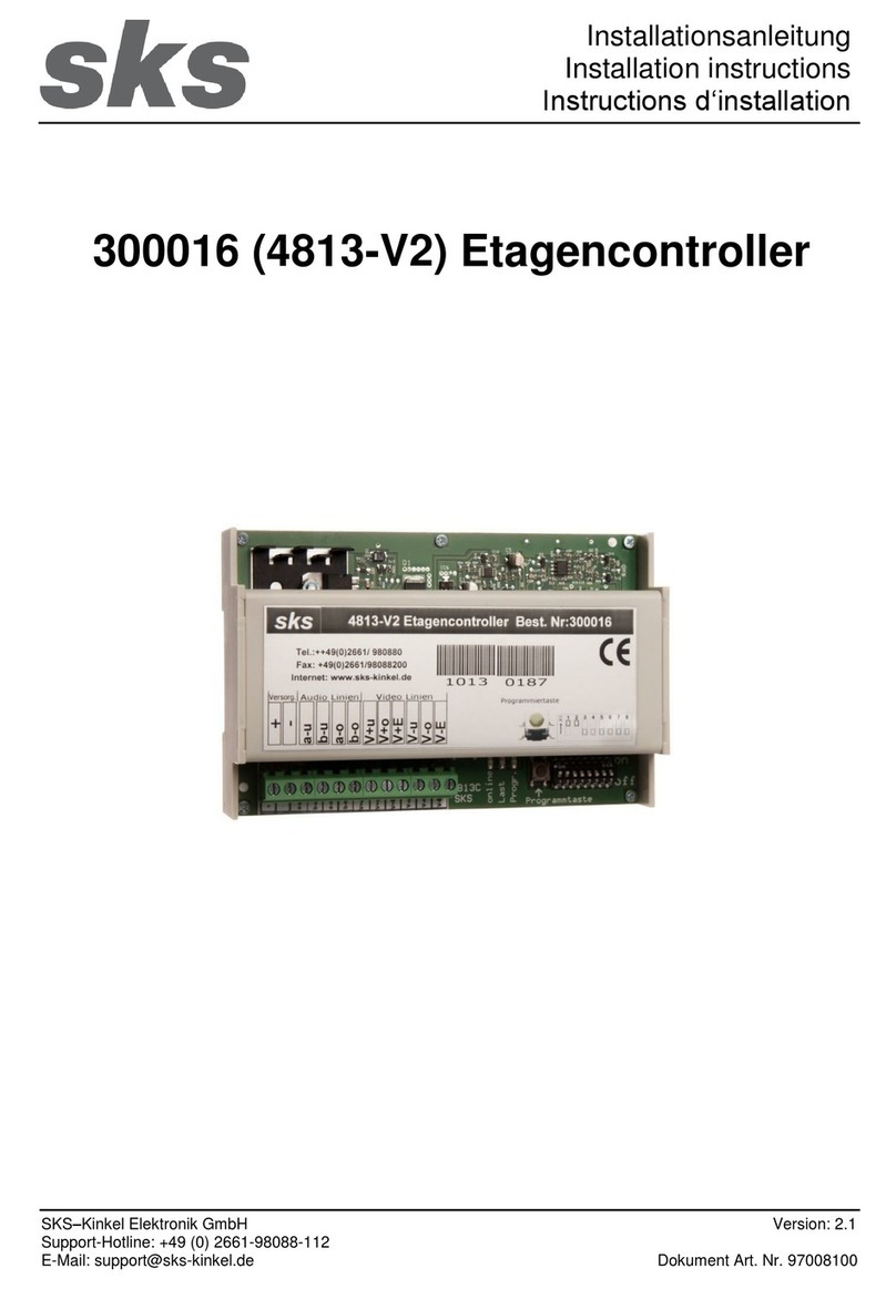
TECSYSTEM NT579 User manual

http://www.tecsystem.asia
NT579
STANDARD
&
DIGITAL
(24 Vdc)
INSTRUCTION MANUAL
TECSYSTEM SHANGHAI
3rd Floor, Block No.5, For-
ward High-tech Industrial
Park,
No.33, Fuhua Road,
Jiading District
SHANGHAI - CHINA
NT579-NT579 RS485
TECSYSTEM SHANGHAI
R.1.4 2015/08/10

2 NT579-NT579 RS485
TECSYSTEM SHANGHAI
1) NT579 TECHNICAL
INTRODUCTION
NT579 is a microprocessor electronic device designed to integrate the ther-
mal control of resin-cast transformers .
The monitoring unit has separated and independent inputs and outputs:
3 3-wire Pt100 inputs for each winding (total 3 inputs)
2 relays for Alarm - Trip signalling
1 FAULT common relay (sensor fault, monitoring unit working anomaly)
SUPPLY
·Rated values: 18~36 Vdc
COMMUNICATION ON DIGITAL OR
AD VERSION
·RS485 MODBUS RTU
INPUTS (Figure 2 Page 11)
3 3-wire PT100 sensor inputs.
·Removable rear terminals
Input channels protected against
electromagnetic noises
OUTPUTS (Figure 2 Page 11)
2 relays ALARM-TRIP with 6A-250Vac
resistive contacts (cosΦ=1)
·1 FAN output at 250Vac Max, 50/60
Hz (max current 12A with cosΦ=1)
·1 alarm relay for sensor fault or
working anomaly (FAULT) with 6A-250Vac
resistive contacts (cosΦ=1)

3
NT579-NT579 RS485
TECSYSTEM SHANGHAI
TESTS AND PERFORMANCES
Assembly in accordance with CE
rules
Protection against electrical noises
CEI-EN-61000-4-4
Dielectric strength 2500 V
alternating current for 1 minute from
power supply + fan output and
PT100 input + modbus output,
power supply + fan output and re-
lays, PT100 input + modbus output
and relays
·Accuracy ±1% full scale value, ±1
digit @25°C
Ambient working temperature from -
20°C to +60°C
Humidity 90% no-condensing
Digital linearity of sensor signal
Sensor self-diagnosis
Program and reading resolution 1
digit
Frontal in polycarbonate IP54
Max. absorption 5VA
Data storage 10 years minimum
Option: protection treatment of
electronic part
·(*) Vibration test IEC 68-2-6
Amplitude ± 1 mm from 2Hz to
13.2Hz Acceleration ± 0.7G from
13.2Hz to 100Hz.
(*) Seismic test according to
IEEE 344-1.987
*Cross reference T154 for construc-
tive analogy.
DISPLAY AND DATA MANAGEMENT
Temperature display ( ° C
TEMPERATURE)
Selected channel and programming
parameter display (CHANNEL/
MESSAGES)
4 LED’s to show the display mode
(SCAN, AUTO, MAN, TMAX)
4 LED’s to show the state of the
alarms relevant to displayed channel
(FAULT, FAN, ALARM, TRIP)
1 LED for RS485 communication (only
for digitasl version)
·Temperature monitoring from 0°C to
200°C
2 alarm thresholds (alarm/trip)
2 ON-OFF thresholds for fan control
(fan)
Sensor diagnostic (Fcc-Foc-Fcd)
Data storage diagnostic (Ech)
Programming access through the front
key
Wrong programming automatic display
Maximum reached temperatures,
alarm storage and sensor fault.
Frontal alarm reset push button
DIMENSIONS
162 x 82 mm depth 130 mm
(terminal boxes included)
Panel cut-out 152x76 mm

4 NT579-NT579 RS485
TECSYSTEM SHANGHAI
2) MOUNTING OF NT579 MONITORING DEVICE
Make a hole in the panel sheet with dimensions 152 x 76 mm.
Firmly tighten the device with the enclosed fixing kit.
3) SUPPLY OF NT579 CONTROL DEVICE
NT579 has a power supply of 18~36Vdc 50-60 Hz
When the monitoring device is directly fed from secondary winding of the
transformer to be protected, it can be damaged by high-intensity overvolt-
ages.
These problems occur if the main switch is connected without load.
Above mentioned problems are much more evident when the voltage 24
Vac voltage is directly taken from the transformer secondary bars and there
is a fixed capacitor battery to phase the transformer itself.
In case you have to replace an existing monitoring unit with a new
one, in order to guarantee its safe and correct working, you must re-
place the sensor/relay/supply connection terminals with the new ter-
minals supplied, provided that they are of a brand different from the
previously mounted ones.
4) ELECTRICAL CONNECTIONS FOR ALARMS AND E VENTILATION
(FIGURE 2 PAGE 19)
Carry out the electrical connections on the removable rear terminals, after
having removed them from the meter.
All relays switch in OFF (as the unit turned off) and does not run any tem-
perature control when you enter one of the following modes: display pro-
gramming Vis, PRG programming, relay test
ALARM and TRIP relays switch only when the set temperature limits are ex-
ceeded.
FAULT relay (Fault) switches when the meter is fed, while gets de-
energised and when:
data memory fault (Ech message)
measuring circuit broken (CAL message)
a fault occurs to Pt100 sensors (Fcc, Fcc or Fcd)
supply voltage is lacking
during the power on reset after the data programming of the unit (local
or via modbus) or after the exit from visualizing program mode.
FAN output can be used to switch ON/OFF the cooling fans of the trans-
former by setting the unit program (table N. 20 at page 10, steps from 6 to
11)

5
NT579-NT579 RS485
TECSYSTEM SHANGHAI
Disconnect the power supply to the instrument before making any
electrical connections
The contact fault is a fault signal, must not be connected to the trip-
ping circuit of the transformer
Is suggested protect the line of fans with a fuse appropriate for the
load to protect the unit
5) TEMPERATURE SENSOR CONNECTION
Each Pt100 temperature sensor has a white wire and two red wires (CEI 75.8
standards).
Figure 2 Page 11 shows the position inside the terminal box of the connection ca-
bles to the monitoring device.
6) MEASURING SIGNAL TRANSFER
All the measuring signal transfer cables for Pt100 must absolutely:
be separated from the power ones
be made with shielded cables and twisted conductors
have at least 0,12 mm²section
be twisted if there is no screen
be firmly fixed inside the terminal boxes
have tinned or silvered conductors
All the “NT” series monitoring units have the sensor signal linearization, with a
max. error of 1% of full scale value.
The maximum length of the extension cables with 0,12 mm² is 50 m.
The maximum length of the PT100 cable, using wires of 1mm²section, is 500m
7) TEMPERATURE SENSOR DIAGNOSTIC
In case of breaking of a temperature sensor mounted on the machine to protect,
FAULT relay immediately switches with the relevant indication of the defective
sensor on the corresponding channel.
Fcc for short-circuited sensor or temperature below –15°C
Foc for interrupted sensor or temperature over 230°C
Fcd for rapid increasing of the reading (see note at page 18).
To remove the message and reset the Fault switching, it is necessary to verify
the Pt100 connections and, in case, replace the defective sensor.
If one channel is in FCD, the condition of ALARM and TRIP of that channel are
cleared
In case of FOC or FCC, the condition of FAN, ALARM and TRIP of the channel
are cleared.
TECSYSTEM has designed an own special cable to transfer the measuring
signals, according to CEI standards, with all the protection requirements pro-
vided for : model CT-ES

6 NT579-NT579 RS485
TECSYSTEM SHANGHAI
8) PROGRAMMED DATA DIAGNOSTIC
In case of breaking of the internal storage or corruption of the programmed data,
just after switching on, the Ech wording is displayed in the messages page with
the relevant reporting of the Fault contact.
In this case, the default setting is restored as in the Pag. 6 in the section “ECH
ERROR”
To remove the Ech wording, press RESET and run programming to insert the de-
sired values.
After the auto reboot of the unit verify the correct memory working; in case it is
damaged and the Ech wording is still displayed, please return the monitoring
unit to Tecsystem for repair).
9) MEASURING CIRCUIT DIAGNOSTIC
In case of breaking of the internal measuring circuit CAL wording is displayed in
the messages page with the relevant reporting of the Fault contact.
Please return the monitoring unit to Tecsystem for repair.
To remove the CAL wording, press RESET.
10) TEMPERATURE DIAGNOSTIC
If one of the temperature sensor detects a temperature higher than 1°C com-
pared to set value as alarm limit, after approximately 5 seconds ALARM relay
switches together with the turning on of ALARM LED if the channel is selected
on the CHANNEL display.
When the release temperature limit is passed, TRIP relay switches together with
the turning on of TRIP LED if the channel is selected on the CHANNEL display
As soon as the taken temperature return to equal or lower values than the set
limit for ALARM and TRIP relay switching, they de-energise with consequent
turning off of the relevant LED’s.
11) COOLING FAN CONTROL
NT579 monitoring unit, if opportunely programmed, can control ON-OFF of fans
accompanying the transformer, according to set temperatures.
12) FAN TEST
It is possible, through programming (HFn), impose that fans are activated for 5
minutes each “xxx” hours, regardless of column or room temperature values
(example: with HFn=001 fans are activated for 5 minutes each hour).
This function has the aim to periodically verify the working of the fans and their
control apparatus during long idle periods.
Loading “no” value this function is inhibited.
During the self-test of the fans, the LED fan is lit on all channels

7
NT579-NT579 RS485
TECSYSTEM SHANGHAI
13) DISPLAY MODE
Pressing MODE key, the display mode is loaded:
SCAN: monitoring unit displays in scansion (each 2 seconds) all the acti-
vated channels
AUTO: monitoring unit automatically displays the hottest channel
MAN: channel temperature manual reading through cursor keys
T.MAX: monitoring unit displays the highest temperature reached by the sen-
sors and possible alarm, trip or fault situations occurred after the last reset.
Select channels with , reset values with RESET.
SCAN AND MAN MODE NOTES.
During the SCAN and MAN mode is possible read status message from CPU.
1) Run cPU: the unit is running correctly
2) Ech Err: the eeprom memory of the unit is corrupted or damaged
3) CAL Err: the measuring circuit of the unit is damaged
4) Pt Err: one or more PT100 sensors are not working well
In case of Err the fault relays will be de-energized.
Only the message can be delayed following the priority over indicated.
RUN CPU.
This message appear when the unit run normally without system errors
ECH ERROR.
Ech means that the statement containing the programming data is corrupted or
damaged. Pressing Reset will delete the message and loads the default values:
Alarm 90 °C, 119 °C Trip, yes Fan, Fan on 70 °C, 60 °c Fan off, Fcd no, no
HFN, Adr 1, Par eve , Bdr 19.2, 4.20 Out scan.
Reprogram the desired values and ensure that these are stored. In case of error
Ech permanent return the equipment to Tecsystem SH for repair..
CAL ERROR.
Cal error means that the measurement circuit of the control unit is not working
properly. The values measured by the sensors PT100 may be incorrect. Return
the equipment to Tecsystem SH for repair.
PT ERROR
This message appears when a sensor PT100 has one of the anomalies indi-
cated in paragraph 7 page 5.
14) WORKING PROGRAM CONTROL
To check the programmed temperature values, shortly press PRG key. viS indi-
cation is displayed on the message display.
By repeatedly pressing PRG key, all the previously loaded values are rolled in
sequence.
During the programming mode the unit is not reading the temperature sensors.
After 1 minute of keyboard no-operation, display-programming procedure will be
automatically left.

8 NT579-NT579 RS485
TECSYSTEM SHANGHAI
15) PROGRAM MODE CONTROL
To enter in programming mode to select the desired setting, press PRG key for
5 sec. Until PrG message appears on the message display.
Follows the step at pag.10 to program the unit.
During the programming mode the unit is not reading the temperature sensors.
After 1 minute of keyboard no-operation, display-programming procedure will be
automatically left without store the programmed values.
16) LAMP TEST
We suggest to regularly carry out monitoring unit LED test.
For this operation shortly press TEST key; all displays turn on for 2 seconds.
If one of the LED’s should not work, we kindly ask you to return the Monitor-
ing unit to
TECSYSTEM.
17) ALARM RELAY SILENCING
If you want to silence the ALARM signal press RESET key: relay de-energises
and LED ALARM, which was fixed, will start to blink.
Silence system is automatically disconnected when all the temperature goes un-
der the ALARM threshold.
If there are errors ECH or FCD, these are reset in order of priority on the alarm
is acknowledged.
18) IMPORTANT NOTICE
Before carrying out the insulation test on the switchboard where the moni-
toring unit is mounted, you have to disconnect it from the mains in order
to avoid serious damages.
NOTES FOR REMOTE PROGRAMMING
Also in the remote programming via ModBus phase you must take into
consideration that the Alarm thresholds must be lower than the Trip thresh-
olds and that the Fan-on thresholds must be higher than the Fan-off
thresholds.
In case you try to load these thresholds in a wrong way, NT579 monitoring
unit won’t proceed with the programming and data storage; therefore in
the coming readings you will read the data relevant to the previous pro-
gramming's.
After having sent a writing request, the monitoring unit will require approxi-
mately 1’’ to store the data in eeprom and a few seconds to reboot; during
storage phase, ModBus module won’t be able to process further request.
If the programming request successfully concludes, the monitoring unit
automatically resets and loads the new loaded values.

9
NT579-NT579 RS485
TECSYSTEM SHANGHAI
The temperature values below zero are displayed in the form of 2's comple-
ment
Channel logs can be read with code 3 from number 1 to number 18
WORKING NOTES
The modbus inside option allow to connect NT579 monitorning unit with a RS485
network
With MODBUS RTU protocol in order to read the data shown in the table at pag.
13 and write the parameters with RW note
MODBUS MAPPING STRUCTURE NOTES
The records modbus are divided into 2 main groups:
From 1 to 18 are present all the temperatures of each channel.
The display of data is carried out WORD 2's complement for the management of
the sign.
The HI byte of WORD represents the sign: 00 = sign +, FF sign -
The LO byte contains the data of temperature
From 41 to 53 are all the status registers and some registers programming.
In this case, there is no registration of the sign

10 NT579-NT579 RS485
TECSYSTEM SHANGHAI
20) PROGRAMMING
N° PRESS EFFECT NOTES
1PRG/SET
Keep pressed PRG key until PrG
message appears on message dis-
play.
Push PRG to start the
programming of the unit
or ENTER to exit.
2PRG/SET ALARM threshold for CH L1-L2-L3
appears
3load desired threshold From 1 to 200°C
4PRG/SET TRIP threshold for CH L1-L2-L3 ap-
pears
5load desired threshold From 1 to 200°C
6PRG/SET FAN YES or NO appears If FAN NO is selected
jump to point 14
7Select desired option Load yes or no
8PRG/SET FAN ON threshold for CH L1-L2-L3
appears
9load desired threshold FAN turning on > FAN
turning off
10 PRG/SET FAN OFF threshold for CH L1-L2-L3
appears
11 load desired threshold FAN turning off < FAN
turning on
12 PRG/SET display shows HFN Fan cyclic test for 5 min-
utes each “n” hours
13 Load desired number of hours no= disabled function
14 PRG/SET FCD threshold appears Fault for temperature
fast increase (°C/sec)

11
NT579-NT579 RS485
TECSYSTEM SHANGHAI
1)If pressing ENT it appears “ALL Err”, it means that TRIP is not
greater of ALARM.. Correct the data.
2)If pressing ENT it appears “FAn Err”, it means that FAN ON is not
greater of FAN OFF. Correct the data.
INTRODUCTION TO MODBUS INSIDE MODULE
MODBUS INSIDE option allows the data transfer on a RS485 network with
MODBUS RTU protocol.
WORKING NOTES
For a correct working of the module it is necessary to load RS485 network
set-up parameters: address, baud rate, parity bit.
Please refer to the programming steps from 16 to 21 shown on the table at
page 8.
The serial communication of the temperature control monitoring unit is ac-
tive just when NT579 is in temperature control working mode in one of the
intended modes (Scan, Auto, Man and T.Max).
When other functions such as programming, programming display and re-
lay test are activated, the ModBus communication is temporarily deacti-
vated.
15 Load desired value (see Page 10) From “no” (excluded function) to 30 °
C/sec
16 PRG/SET ADR appears Unit Modbus address
17 Load the desider modbus address From 1 to 255
18 PRG/SET BDR appears Modbus Baud rate
19 Load the desider modbus baud rate From 2.4 to 38.4 baud
20 PRG/SET PAR appears Modbus parity bit
21 Load the desider modbus parity bit No, even or odd.
N° PRESS EFFECT NOTES
22 PRG/SET display shows END Programming end
23 ENT Loaded data storage and program-
ming exit
Err: wrong programming
for values indicated by Err
message
24 PRG/SET Return to step 2

12 NT579-NT579 RS485
TECSYSTEM SHANGHAI
19) FRONT PANEL
Keyboard
MessagesAlarms Display
FIGURE 1
Keyboard
Messages
DATA TRANSMISSION ON MODBUS NETWORK
The MODBUS INSIDE option allows to connect NT579 monitoring unit with
a RS485 network with Modbus RTU protocol in order to read and write the
data shown in the table MODBUS MAPPING at pag.13. The unit is always
in slave mode.
RS485 ELECTRICAL CONNECTIONS
As far as the signal cable to be used in order to ensure a proper network
working is concerned, we recommend to follow what laid down by EIA
RS485 standard which suggests to use a 24AWG duplex cable.
The duplex cable which connects all the units in RS485 could require the
activation of the 120 ohm termination on the last unit of the series.
Connect the duplex cable paying attention to polarities and lay the network
avoiding to make sharp bends or ring windings in order not to modify the
line impedance.
If necessary, also the GND terminal for grounding is available
DATA FRAME
The frame in asynchronous transmission is composed of: 1 start bit, 8 data
bits, 1 parity bit (even or odd, if the parity has been set) and 1 stop bit (2
stop bit if no parity is selected).
Admitted baud rates are: 2400, 4800, 9600, 19200 and 38400 b/s.
Where no otherwise specified, the word length (DATA) is of 16 bits.

13
NT579-NT579 RS485
TECSYSTEM SHANGHAI
DATA PACKET
A complete sequence of request/answer is composed as follows:
Master request.
SLAVE ADDRESS - 1 byte
FUNCTION CODE - 1 byte
DATA - variable, they depend by the function code
CRC - 2 bytes
Slave answer.
SLAVE ADDRESS - 1 byte
FUNCTION CODE - 1 byte
DATA - variable, they depend by the function code
CRC - 2 bytes
29) FUNCTION CODE
ModBus module supports the following function codes:
3(10):- holding register reading
16(10):- multiple register writing
If ModBus receives a message and a CRC error is detected, no answer is
given.
30) CODE 3(10).
Request:
Slave address, code 3(10), Starting address HI, Starting address LO, Number of
Point HI, Number of Point LO, Crc LO, Crc HI.
Answer:
Slave address, code 3(10), Byte count, Data HI, Data LO……., Crc LO, Crc HI.
ERROR CODES (exception code)
In case of wrong request ModBus will answer with modified codes and codified
errors according to the following points:
1: - Non-supported function code
2: - Wrong data address
3: - Wrong data (for instance length)
4: -illegal data(for value)

14 NT579-NT579 RS485
TECSYSTEM SHANGHAI
POLLING FREQUENCY
The max. time to give an answer to a calling never exceeds 1 second; therefore
we suggest not to use polling frequencies with lower duration.
CRC CALCULATION
This protocol includes 2 CRC-16 bytes in each transmission. The characteristic
polynomial (11000000000000101B) is used for the calculation and the result is
“hung” at the end of the package. The polynomial is used in the reverse order
with the most significant bit suppressed because useless for calculation.
PARAMETER DESCRIPTION
A - 16-bit register
AL - At low side
AH - At huigh side
i,j, - KWH METERS
(+) - EXCLUSIVE OR
Di - Frame data «i»th of the packet
N - number of byte of the packet excluded 2 belonging to CRC
G - Polynomial : 1010-0000-0000-0001
shr - right shift
ALGORITHM
1) 0xFFFF -> A
2) 0 -> i
3) 0 -> j
4) Di (+) AL -> AL
5) j +1 -> j
6) shr A
7) if carry then G (+) A -> A
8) if NOT j=8 then go to 5
9) i +1 -> i
10) if NOT i = N then go to 3
11) A -> in CRC (result is in the order L,H)
CODE 16(10).
Request:
Slave address, code 16(10), Starting address HI, Starting address LO, Num-
ber of Point HI, Number of Point LO, Byte count, Data HI, Data LO…….,
Crc LO, Crc HI.
The alarm thresholds (registers 3-4-5-6) are written only for channel L1

15
NT579-NT579 RS485
TECSYSTEM SHANGHAI
Address
HI (10)
Address
LO (10) Data HI Data LO Note 1 Note
2
R: read
W:write
RW:
read/
write
0 1 2’compl.
sign
2’compl.
Ch L1 tem-
perature
from –
20°to
230
R
0 2 2’compl.
sign
2’compl.
Ch L1
maximum
temperature
from 1°
to 220 R
0 3 2’compl.
sign
2’compl.
Ch L1tem-
perature
alarm set
point
from 1°
to 220 RW
0 4 2’compl.
sign
2’compl.
Ch L1 tem-
perature
trip set
point
from 1°
to 220 RW
052’compl.
sign
2’compl.
Ch L1 tem-
perature
Fan on set
point
from 1°
to 220
RW
062’compl.
sign
2’compl.
Ch L1 tem-
perature
Fan off set
point
from 1°
to 220
RW
072’compl.
sign
2’compl.
Ch L2 tem-
perature
from –
20°to
230
R
082’compl.
sign
2’compl.
Ch L2
Maximum
temperature
from 1°
to 220
R

16 NT579-NT579 RS485
TECSYSTEM SHANGHAI
MODBUS MAPPING
Address
HI (10)
Address
LO (10) Data HI Data LO Note 1 Note
2
R: read
W:write
RW:
read/
write
092’compl.
sign
2’compl. Ch
L2 tempera-
ture
alarm set
point
from 1°
to 220
R
0 11 2’compl. sign
2’compl. Ch L2 tem-
perature from 1°to 220 R
Fan on set point
0 12 2’compl. sign
2’compl. Ch L2 tem-
perature from 1°to 220 R
Fan off set point
0 13 2’compl. sign 2’compl. Ch L3 tem-
perature
from –20°to
230 R
0 14 2’compl. sign
2’compl. Ch L3
maximum tempera-
ture
from 1°to 220 R
0 15 2’compl. sign
2’compl. Ch L3 tem-
perature
from 1°to 220 R
alarm set point
0 16 2’compl. sign
2’compl. Ch L3 tem-
perature
from 1°to 220 R
trip set point
0 17 2’compl. sign
2’compl. Ch L3
temperature from 1°to
220 R
Fan on set point

17
NT579-NT579 RS485
TECSYSTEM SHANGHAI
Address HI (10)
Address LO
(10)
Data HI Data LO Note 1 Note 2
R: read
W:write
RW: read/write
0 18 2’compl. sign
2’compl. Ch L3
temperature
from 1°to 220 R
Fan off set point
0 41 0 CPU Status Controller status See CPU status
note R
0 42 0 Ch L1 status channel L1
Status
See CHn status
note R
0 43 0 Ch L2 status channel L2
Status
See CHn status
note R
0 44 0 Ch L3 status channel L3
Status
See CHn status
note R
0 45 0 Ch L1 story channel L1
Alarm history
See CHn story
note
R
0 46 0 Ch L2 story channel L2
Alarm history
See CHn story
note
R
0 47 0 Ch L3 story channel L3
Alarm history
See CHn story
note
R
0 48 0 HFN
setting fan test
cycle (hours)
0=No test
RW
1~200h
0 49 0 FCD
detector tem-
perature incre-
ment fast
0=No FCD
RW
1~30°/sec

18 NT579-NT579 RS485
TECSYSTEM SHANGHAI
CPU STATUS
BIT 7 BIT 6 BIT 5 BIT 4 BIT 3 BIT 2 BIT 1 BIT 0
Not used Not used Not used Not used PT Fault V_rif Fault FCD Fault E2P Error
CH A-b-c STATUS
BIT 7 BIT 6 BIT 5 BIT 4 BIT 3 BIT 2 BIT 1 BIT 0
Not used TRIP ALARM Not used FAN FCD FOC FCC
CH A-b-c STORY
BIT 7 BIT 6 BIT 5 BIT 4 BIT 3 BIT 2 BIT 1 BIT 0
Not used TRIP ALARM Not used Not used Not used FOC FCC
Address HI (10)
Address LO
(10)
Data HI Data LO Note 1 Note 2
R: read
W:write
RW: read/write
0 51 0 Address Modbus address 1~255 R
0 52 0 Bdr Modbus baud
rate
0=2400 Baud
R
1=4800 Baud
2=9600 Baud
3=19200 Baud
4=38400 Baud
0 53 0 Parity Modbus parity
bit
0=No Parity
R
1=even Parity
2=odd Parity
CH L1-L2-L3 STATUS
CH L1-L2-L3 STORY

19
NT579-NT579 RS485
TECSYSTEM SHANGHAI
FAULT DIAGNOSTIC CAUSES AND REMEDIES
Monitoring unit doesn’t turn on, even if
the terminals are fed.
Connector not well placed inside its
seat. Connection cables are not tight-
ened in the terminal. Burnt out feeder.
Take out and give supply again.
Check the polarity of the power connec-
tion (Page 21 power supply)
One of the three/four channels is in
FAULT for FOC/FCC
Check Pt100 sensor connections.
Possible defective sensor.
Replace the damaged sensor.
When turning on, “ECH” indication ap-
pears
A strong disturbance damaged the
stored dataplease refer paragraph 8.
If this problem should persist, please
contact TECSYSTEM SH Technical De-
partment.
All the Pt100 sensor are in FCC.
Wrong sensor connections. Terminal
box connected inside out.
Check connections and terminal box.
The temperature of the sensors is un-
der –15°C.
All the Pt100 sensor are in FOC.
Wrong sensor connections. Terminal
box connected inside out.
Check connections and terminal box.
The temperature of the sensors is over
230°C.
Temperature indicated by one or more
channels is wrong.
Contact TECSYSTEM SH Technical
Department
Sudden trip of the main switch. Tem-
perature is on standard levels. Just one
channel caused the trip.
Verify through T.MAX function possible
defective sensors.
Replace the sensor. Check the measur-
ing signal terminal box.

20 NT579-NT579 RS485
TECSYSTEM SHANGHAI
21) NOTES ABOUT FCD FUNCTION
NT device series have an innovative control function combined with the
Pt100 sensor dynamic state.
If a temperature sensor should accidentally break down, the defect turns out
with a fast increase of its resistance and therefore of the temperature
registered by the monitoring unit.
It is obvious that this increase is not consequential to the increase of power
of the machine to be protected, whether it is a motor or a dry or
encapsulated transformer.
Therefore it is advisable to discriminate the state of the sensor and report a
Fault notification rather than an Alarm or, worse, a Trip signal.
In case of temperature control for electrical motors, the fast increase of the
temperature could be the consequence of the working with jammed rotor
and not of defective sensor; in this case the Fault relay, once energised,
makes evident this anomalous condition for the motor working.
By activating the FCD function it is possible to have on 54-55 contacts a
Fault signal when the temperature registered by a Pt100 increases with a
speed higher than “n” °C/sec (loadable from 1 to 30).
Depending on the loaded value, you can have a different sensitivity, which
can be useful for various applications:
-from 1 to 10: high sensitivity, for instance useful to immediately report a
jammed rotor in a motor.
-from 10 to 20: medium sensitivity, useful to have indications for possible
noises which affect the sensor reading, connection problems or defective
sensors.
-from 20 to 30: low sensitivity, useful for applications where an higher
sensitivity could give rise to faults for undesired FCD.
- loading “no”,FCD function is disabled.
When a channel is in Fault condition for FCD, relevant Alarm and trip
signalling are inhibited in order to just report the anomaly for too fast
increase of the temperature.
Press Reset to cancel the FCD signalling of all the channels and restore the
fault relay.
Table of contents
Other TECSYSTEM Controllers manuals
TECSYSTEM
TECSYSTEM T154 Series User manual

TECSYSTEM
TECSYSTEM NT935 ETH User manual

TECSYSTEM
TECSYSTEM VRT200 User manual

TECSYSTEM
TECSYSTEM MULTIMODULE 133 User manual

TECSYSTEM
TECSYSTEM NT935-4 User manual

TECSYSTEM
TECSYSTEM NT935 User manual

TECSYSTEM
TECSYSTEM NT539 User manual

TECSYSTEM
TECSYSTEM NT210 K User manual
TECSYSTEM
TECSYSTEM T154-4 Manual