TeeJet 814-FM User manual

814-FM
Monitor
Programming and Operating Manual
(2.00)
98-70014-R0
MI814-FM Programming and Operating Manual, 03/2000 1 of 17

Table Of Contents
TABLE OF CONTENTS ........................................................................................................................................................................ 2
INSTALLATION..................................................................................................................................................................................... 3
PUMP CUT-OFF INSTRUCTIONS ...............................................................................................................................................................4
POWERING CONSOLE ON/OFF ........................................................................................................................................................ 5
POWER ON.............................................................................................................................................................................................5
POWER OFF............................................................................................................................................................................................5
OVERVIEW OF MONITOR DISPLAYS............................................................................................................................................. 6
DISPLAYS................................................................................................................................................................................................ 7
JOB VOLUME.......................................................................................................................................................................................... 7
JOB FLOW RATE.....................................................................................................................................................................................7
PRESSURE /FLOW RATE......................................................................................................................................................................... 8
TOTAL VOLUME.....................................................................................................................................................................................8
AUTOMATIC FILLING .............................................................................................................................................................................9
PROGRAMMING GUIDELINES ....................................................................................................................................................... 10
IMPORTANT PRELIMINARY INFORMATION ...........................................................................................................................................10
PROGRAMMING THE 814-FM SPRAYER CONTROL SYSTEM ............................................................................................... 11
UNITS...................................................................................................................................................................................................11
FLOW METER PULSES ..........................................................................................................................................................................11
Manual Entry..................................................................................................................................................................................11
Automatic Calibration....................................................................................................................................................................12
PRESSURE TRANSDUCER LOW PRESSURE CALIBRATION......................................................................................................................13
PRESSURE TRANSDUCER MAXIMUM RATING (P HI) ............................................................................................................................. 14
FILL VALVE .........................................................................................................................................................................................14
DATE/TIME ..........................................................................................................................................................................................15
PRINTING ............................................................................................................................................................................................. 16
JOB REPORT .........................................................................................................................................................................................16
TOTAL REPORT ....................................................................................................................................................................................16
HIDDEN TOTAL VOLUME COUNTER........................................................................................................................................... 17
OEM REPORT ......................................................................................................................................................................................17
MI814-FM Programming and Operating Manual, 03/2000 2 of 17
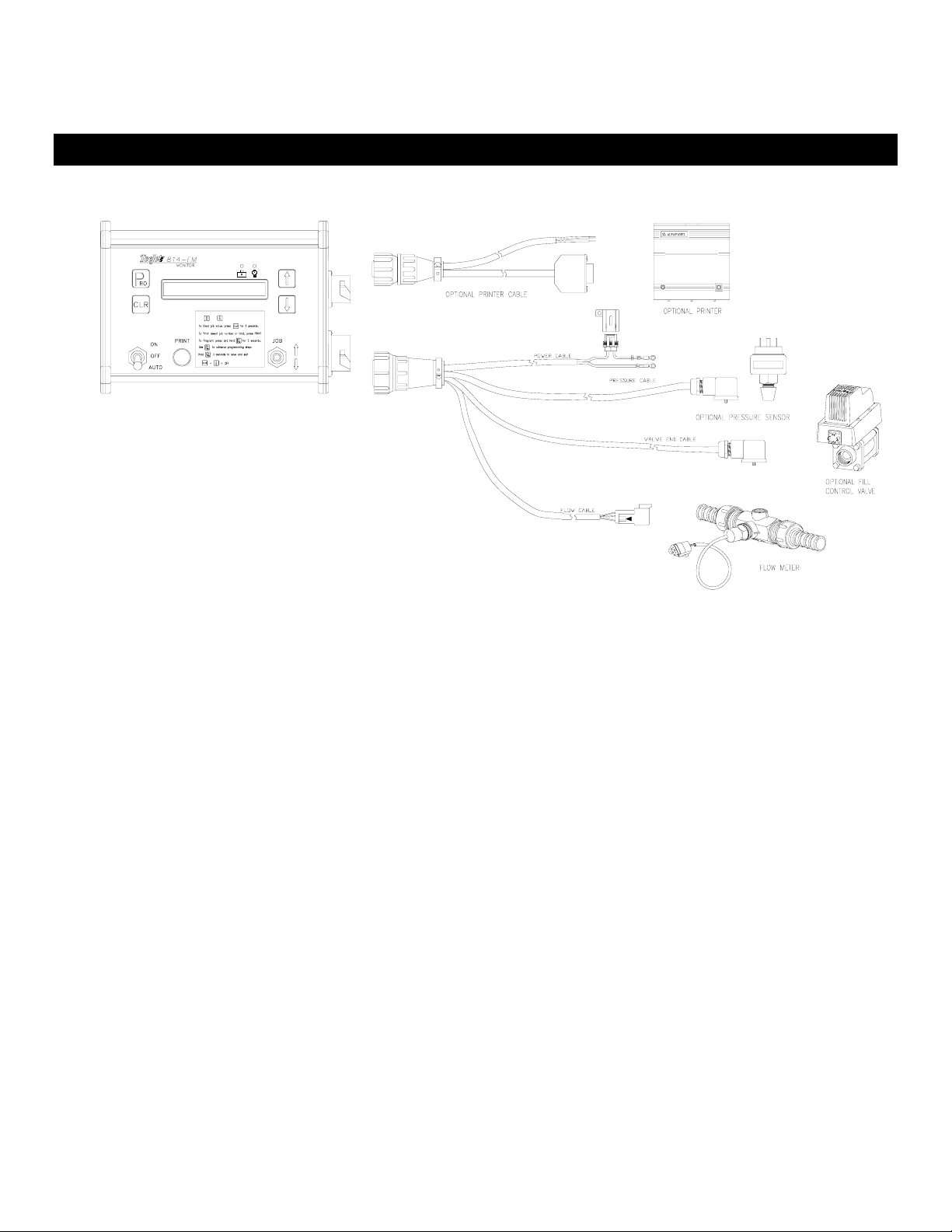
Installation
☛The TeeJet 814-FM monitor is powered by +12VDC. The fused power lead (brown wire) should
go to the positive terminal of the battery. The blue or white wire to the negative or ground
terminal of the battery.
☛The flow meter should be plumbed so that all liquid passing through it is intended to be
measured.
☛The flow meter cable lead should be extended and connected to the the flow meter.
☛The pressure sensor (if used) can be installed at any point in the plumbing system. It should be
mounted in a verticle position on a short stand pipe to help prevent damage from freezing
temperatures.
☛The pressure sensor lead should be extended and connected to the pressure transducer, if
used. If no pressure transducer is used, this cable lead can be tied back for possible future use.
☛The valve lead should be extended and connected to the optional auto fill valve. If an auto fill
valve is not used, this cable can be tied back for possible future use.
☛The auto fill valve used with this system must be a negatively switched valve. This system can
also be used to disengage a pump if desired. Refer to the Pump Cut-off instructions in the
following section.
☛If an optional printer will be used with the system, it requires a separate cable connection to the
console. The printer has two connections, one is the data connection and the other is power for
the printer.
MI814-FM Programming and Operating Manual, 03/2000 3 of 17

PUMP CUT-OFF INSTRUCTIONS
While the 814-FM is capable of switching an auto fill valve, it can also switch an electric transfer
pump. The 814-FM is limited to switching 1.8 amps directly. If the pump requires a higher current to
activate, a relay must be used to isolate/protect the 814-FM. When using a relay for switching higher
currents, it is important that the power supply for the relay and load come through a correctly sized
fuse and directly from the pump power source, not the 814-FM. Keep in mind that the 814-FM is
negatively switched and the relay will need to be wired accordingly.
MI814-FM Programming and Operating Manual, 03/2000 4 of 17

Powering Console On/Off
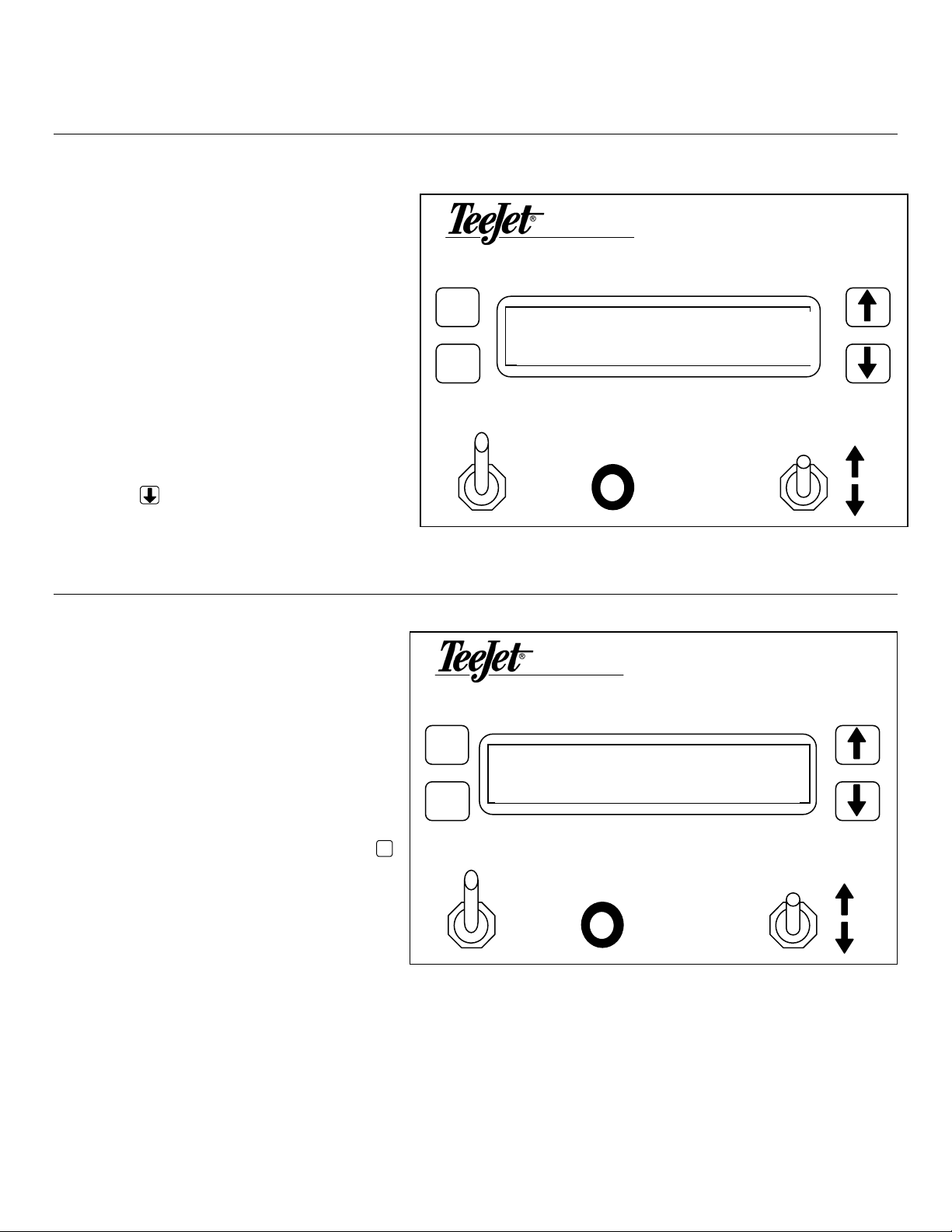
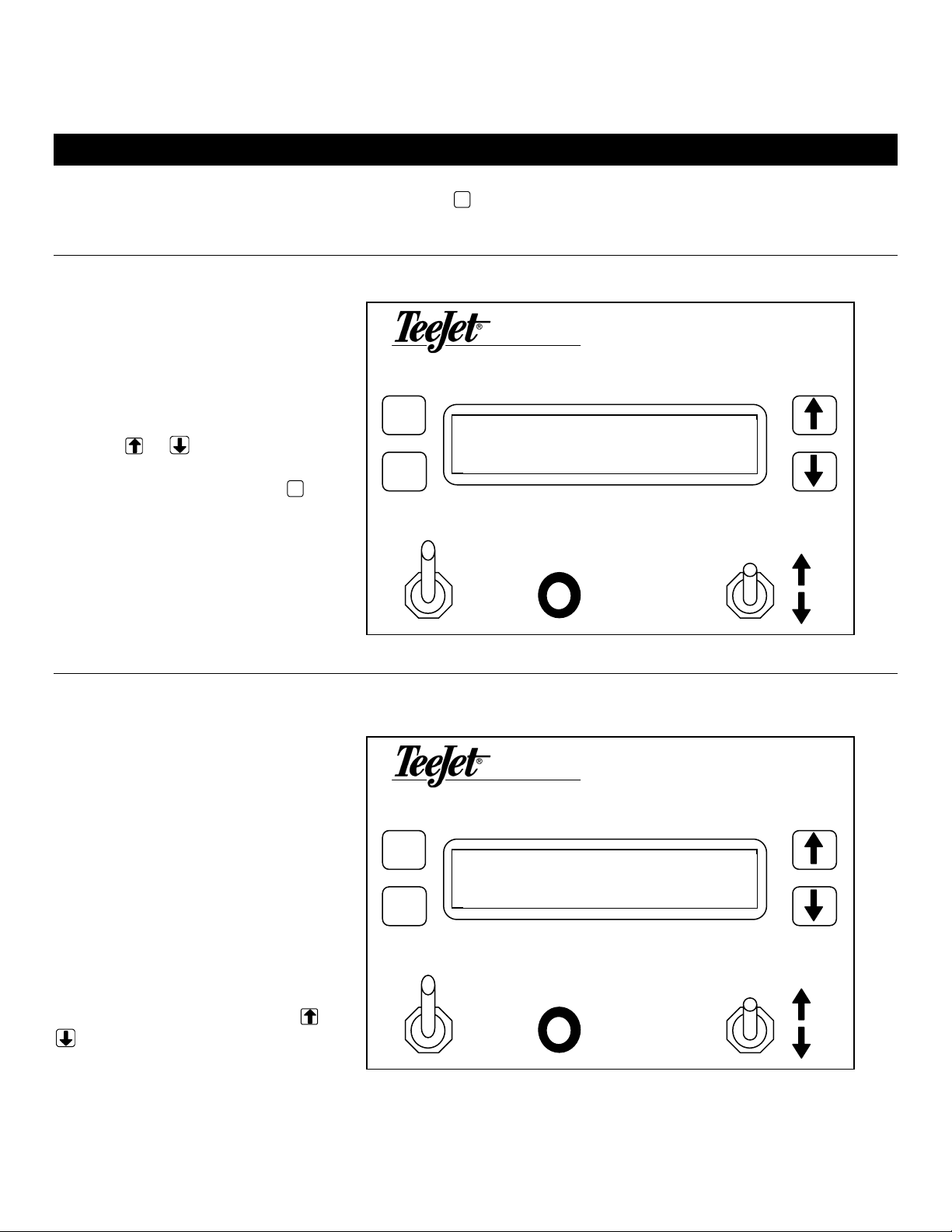
POWER ON
After all the necessary electrical
connections have been made
the console is ready to be
powered on. To power the 814-
FM on press the P
RO key once.
Initially the console will display
the software version of the
console in the display for
approximately 2 seconds. This
information will be needed
when calling for support. After
2 seconds the display will show
the normal operating view.
814-FM
MONITOR
P814-FM V 2.00A
RO
CLR
JOB
PRINT
ON
OFF
AU
T
O
POWER OFF
814-FM
To manually power the console
off, press the and CLR keys
simultaneously. The console
will then save any new
information (volume counters)
to memory and will power off.
MONITOR
P
RO
CLR
Note: The console also has
an Auto Power Down feature.
The console will power itself
off after 10 minutes if not
receiving any inputs.
JOB
PRINT
ON
OFF
AU
T
O
MI814-FM Programming and Operating Manual, 03/2000 5 of 17
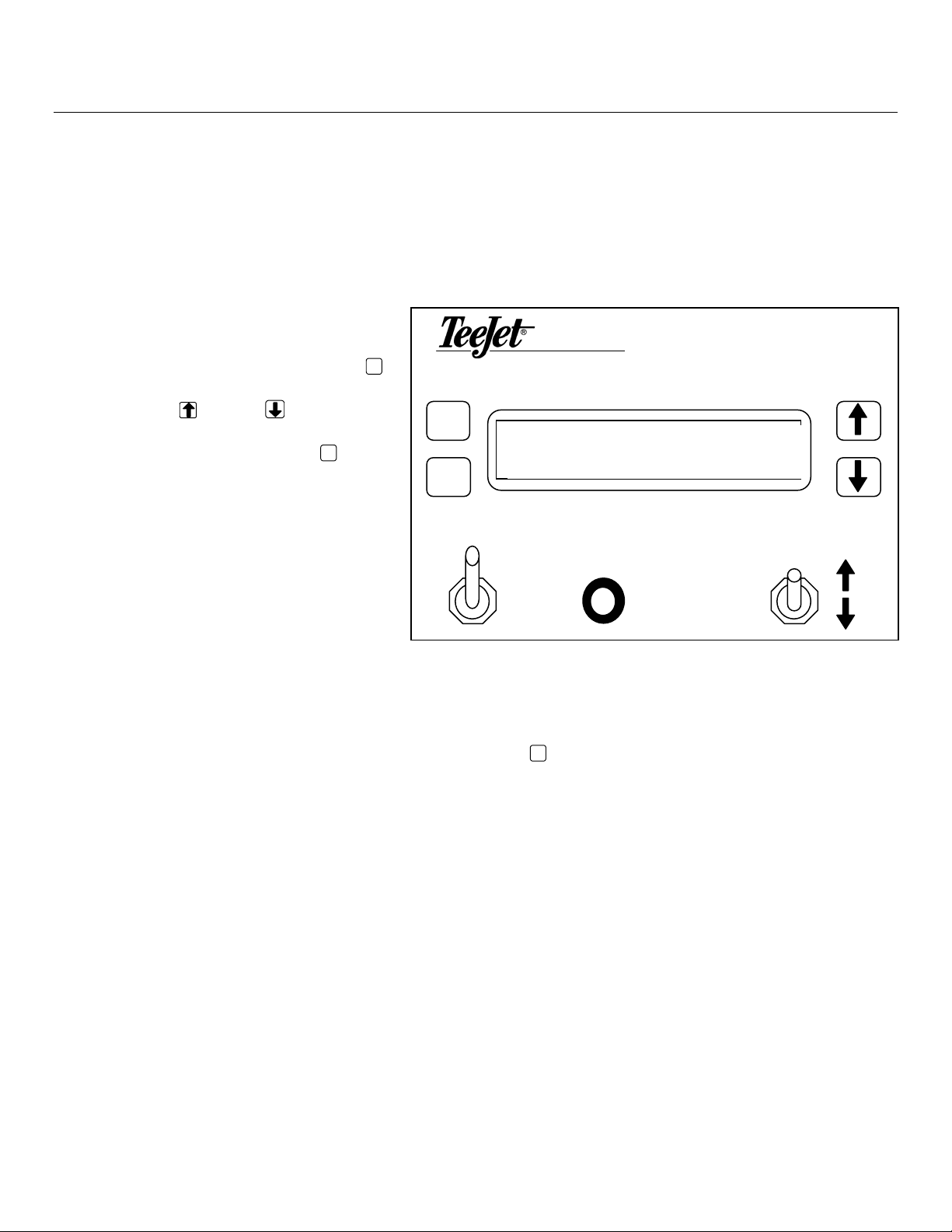
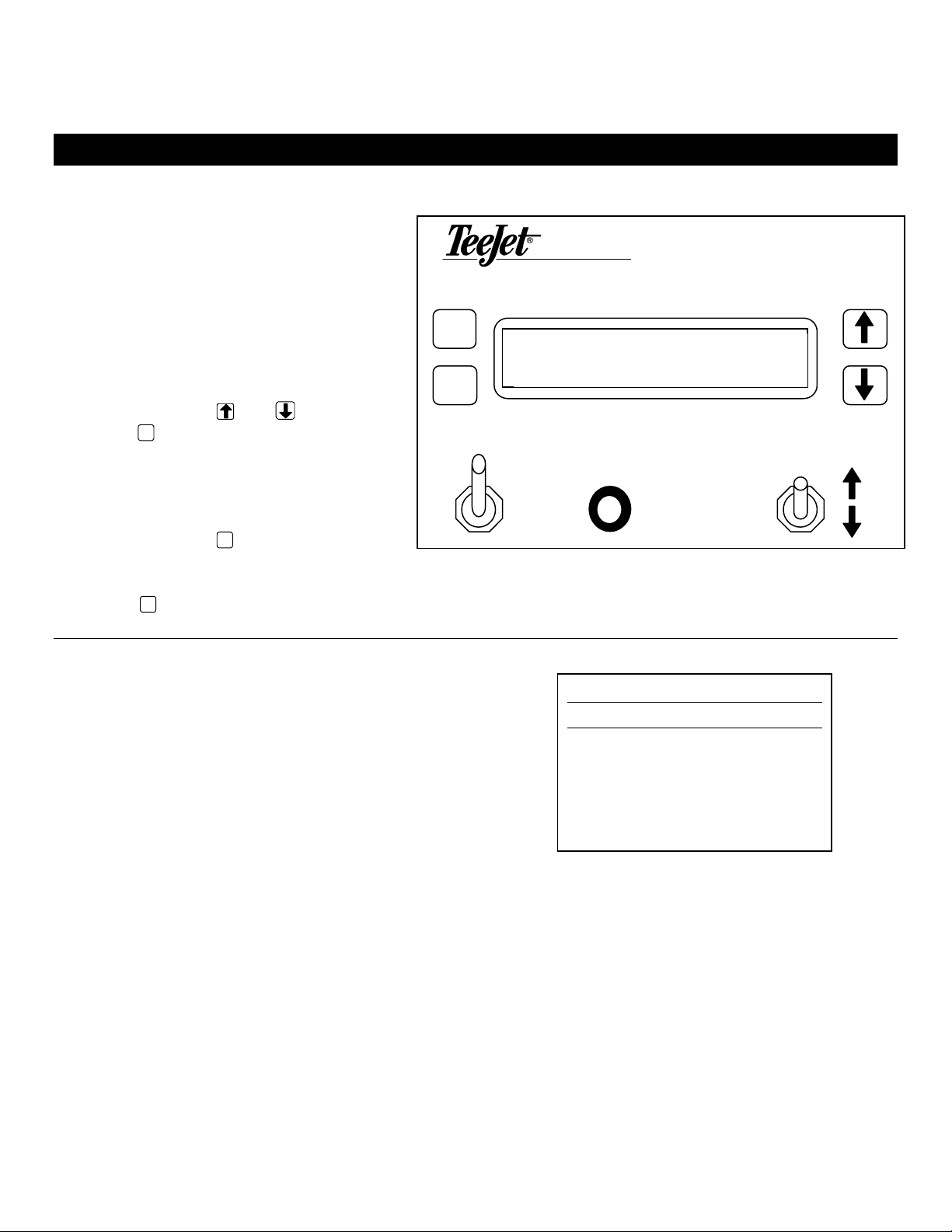
Overview of Monitor Displays
•and keys are used for scrolling through the list of display information or for changing values
when a value is flashing.
•Holding the
CLR key for 3 seconds is used to clear a job volume memory (only one job or all job
memories when the total counter is displayed).
•A short press on the P
RO key allows you to enter amount to be filled if the Fill Valve option has been
activated. You can only enter this step when the job number is visible.
•The fill valve is always switched ON when the switch is in the ON position.
•The fill valve will be automatically controlled when the switch is in the AUTO position.
•The Job selection switch is used to scroll through the possible job settings. You can only change
jobs when the job number is visible.
•The print button is used to print the volume of the selected job or to print the list of all non zero
jobs and the total value.
•GAL (L) or GPM (LPM) is flashing on the screen when automatic filling is busy. Automatic filling
can be stopped by pressing shortly on the CLR key.
Very Important: Whenever you are working around a sprayer or chemicals, be sure to wear
protective clothing and eyewear.
MI814-FM Programming and Operating Manual, 03/2000 6 of 17
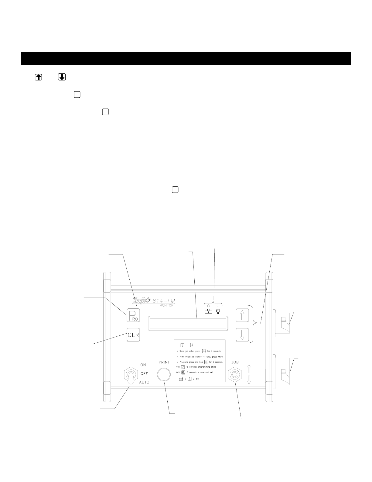
Display
Backlit LCD display for
24 hour operations.
Sensor Monitors
LED’s light when
sensor is sending
signals to console
ON/OFF/AUTO Switch
Used to activate the fill valve/pump.
Auto selection controls shut-of
automatically
Main Connection
Connection for main
cable with leads to
power, sensors and
vales if used.
Data Connection
Used for connection
of optional printer.
Power
Press 1 time to power the
console on.
Easily Accessible Program Mode
Press for 3 seconds to enter/exit program
mode.
Print Button
Used with optional printer
to print individual job
reports or a total report of
all jobs.
Display Selection
Use these keys to chose which
display to view. Chose Job
Volume, Job Flow Rate,
Pressure/Flow Rate or Total
Volume
Clear Function
Used to clear individual job
memories or the total volume
memory. Press and hold to
clear
Job Selection Switch
Use to change the display
from one job to the next.

Displays
JOB VOLUME
814-FMIn this display the console will show the
total accumulated volume for the job
number selected.
MONITOR
P
To change to a new job selection use
the job selection switch. Pushing up on
the job switch will increase the job
number, down will decrease the job
number.
JOB 3 150.0 GAL
RO
CLR
JOB
This volume will be counted any time
that the master boom switch is in the
ON or AUTO position and flow is going
through the flow meter.
PRINT
ON
OFF
AU
T
O
Maximum amount 6500 Gallons
(6500 Liters)
To clear this value, press and hold the CLR key for 3 seconds.
Press the key to advance to the next display.
JOB FLOW RATE
814-FM
In this display the console will show the
current flow rate in GPM (LPM) that is
going through the flow meter.
MONITOR
P
The flow rate will be displayed any time
flow is going through the flow meter
regardless of the position of the master
boom switch. In this example, the total
volume is still being accumulated in Job
JOB 3 75.0 GPM
RO
CLR
JOB
Press the key to advance to the next
display. PRINT
ON
OFF
AU
T
O
MI814-FM Programming and Operating Manual, 03/2000 7 of 17
PRESSURE /FLOW RATE
This display shows the current pressure
and flow rate in GPM (LPM). 814-FM
MONITOR
The flow rate and pressure will be
displayed any time flow is going through
the flow meter and pressure is acting on
the pressure transducer, regardless of the
position of the master boom switch.
P45 PSI 75.0 GPM
RO
CLR
Note: This display is only available
when a pressure transducer has been
installed, connected and properly
programmed into the console. JOB
PRINT
ON
OFF
Press the key to advance to the next
display.
AU
T
O
TOTAL VOLUME
814-FM
This display shows the total
accumulated volume for all jobs.
MONITOR
P
This volume will be counted any time
that the master boom switch is in the ON
or AUTO position and flow is going
through the flow meter.
TOTAL:2500.0 GAL
RO
CLR
To clear this value, press and hold the CLR
key for 3 seconds. JOB
PRINT
ON
Note: Clearing this value also clears
all individual job totals. Insure all
individual job information has been
OFF
AU
T
O
printed and/or recorded before clearing
the Total Volume.
MI814-FM Programming and Operating Manual, 03/2000 8 of 17
AUTOMATIC FILLING
Automatic filling is used to deliver a predefined volume of liquid by opening a filling valve (switching
on a pump) until the desired volume has been measured. The electric fill valve is driven by the
console.
To use the automatic filling feature the console must first be programmed for this function. Refer to
the “Fill Valve” step in the programming section of this manual. This step should be set to “YES”.
To begin auto filling, first select the job
number you would like to use with the
Job Selection switch. Next press the P
RO
key once to access the amount to be
filled. Use the and/or keys to
adjust the volume to be filled. After the
volume has been set, press the P
RO again.
This will advance back to the job
selection display. The GAL (L) or GPM
(LPM) text will be flashing to indicate that
the console is waiting for further action.
Next move the master switch to the
AUTO position. This will activate the fill
valve (transfer pump) to begin the filling
process.
814-FM
MONITOR
PFILL: 0.0 GAL
RO
CLR
JOB
PRINT
ON
OFF
AU
T
O
During the filling process you can temporarily close the filling valve by turning the master switch back
to the OFF position. The filling is continued after switching back to the AUTO position. When the
desired volume is reached the console will automatically close the filling valve (disengage the pump).
If you want to stop the automatic filling you can press the CLR key and the GAL (L) or GPM (LPM) text
will stop flashing and the fill valve will be closed.
The filling valve can be driven manually by switching the master switch to the ON or OFF positions.
MI814-FM Programming and Operating Manual, 03/2000 9 of 17

Programming Guidelines
Make sure that all hardware components are properly installed and tested. Before you start the
programming process you should first be sure that the console and all sensors are working properly.
IMPORTANT PRELIMINARY INFORMATION
Before you begin, it is recommended that you review the following Programming Guidelines that
control the programming process:
☛To enter the program mode press and hold the P
RO key for 3 seconds. The master switch must be
in the off position.
☛To exit the program mode press and hold the P
RO key for 3 seconds, your inputs will be stored and
the computer will exit the program mode. This action can be done at any time but will not be
necessary until the last programming step has been completed.
☛To increase the value of a programmable digit, press the key. To decrease the value, press the
key. These keys are located directly to the right of the display. For some programming steps,
pressing and holding the or key will change the programmable value rapidly. Pressing the
or key once will change the value by one increment.
☛Pressing the and keys simultaneously in some programming steps will will start an
automatic calibration.
☛A short press of the CLR key in program mode will reset the value to its default value.
☛Holding the CLR key for 2 seconds will clear the value to zero.
☛Pressing the P
RO key will advance you to the next programming step. After the last programming
step, the console will return to the first programming step.
☛Note: Due to differences in fonts, some letters on the displays shown in this manual are
not identical with the corresponding letters on the display of the controller. We tried to
match them as close as possible.
MI814-FM Programming and Operating Manual, 03/2000 10 of 17
Programming the 814-FM Sprayer Control System
To enter the Program Mode, press and hold the P
RO key for 3 seconds. The first programming step
should appear on the display.
UNITS
814-FM
In this step you indicate if you will
be using US units (GPM, GAL, PSI)
or SI Standard International units
(l/min, L, bar).
MONITOR
P
>Units: US
RO
Use the or keys to adjust the
value. Once you have selected the
appropriate units, press the P
RO key
to advance to the next
programming step.
CLR
JOB
PRINT
ON
OFF
AU
T
O
FLOW METER PULSES
In this step the flow meter
calibration number can be entered
manually from the factory flow
meter tag or an auto calibration
procedure can be activated to
determine the flow meter pulses
based on a known volume of fluid.
814-FM
MONITOR
P> 650 puls/l
RO
Manual Entry CLR
First locate the factory flow meter
tag on the flow meter. If this varies
from the default value (it usually
does) of the console, use the or
keys to modify the value.
JOB
PRINT
ON
OFF
AU
T
O
MI814-FM Programming and Operating Manual, 03/2000 11 of 17

Automatic Calibration
To complete an automatic calibration
of the flow meter, press the and
keys simultaneously. This will clear
the existing value and initiate the
calibration procedure.
814-FM
MONITOR
P
Start auto cal
RO
“Start auto cal” will be displayed in
the screen. This indicates that the
controller is ready to begin the
calibration process.
CLR
JOB
PRINT
ON
OFF
AU
T
O
814-FM
Engage the sprayer pump. Now turn
the Master switch to “ON” and begin
spraying or pumping a known volume
of fluid (e.g. 100 gallons or 100
liters). As you spray the known
amount, the console will count the
pulses.
MONITOR
PAuto cal. 132657
RO
CLR
After the known volume has been
pumped out, turn the Master switch
off to stop counting pulses.
JOB
PRINT
ON
OFF
AU
T
O
MI814-FM Programming and Operating Manual, 03/2000 12 of 17

Now press the P
RO key. The console
will now ask what volume was
pumped (max 9999). 814-FM
MONITOR
Use the or keys to adjust the
value to match the volume
transferred/pumped (in gallons or
liters).
PVolume: 100 GAL
RO
CLR
Now press the P
RO key to return to
the programming mode. Your new
flow meter calibration number will
be displayed. To accept this value
press the P
RO to advance to the next
step. If you wish to repeat the
calibration procedure refer to the
steps above.
JOB
PRINT
ON
OFF
AU
T
O
Note: To achieve an accurate flow meter calibration, a volume of at least 50 gallons should be
pumped during calibration. The more volume used for calibration the more accurate the flow
meter will be.
PRESSURE TRANSDUCER LOW PRESSURE CALIBRATION
This step is used to determine
the “0” pressure setting of the
pressure transducer installed in
your system (if used). The
pressure transducer used with
the 814-FM is a current type
transducer and uses a 4-20 mA
reading. 4.0 mA represents 0
pressure.
814-FM
MONITOR
P>4.0 mA 0 Psi
RO
CLR
If a different pressure transducer
will be used with the system
check the specifications of that
transducer in the manufacturers
literature.
JOB
PRINT
ON
OFF
AU
T
O
Press the P
RO key to advance to the
next step.
If a pressure transducer is NOT being used, press the P
RO key to skip this step and advance to the next
programming step.
MI814-FM Programming and Operating Manual, 03/2000 13 of 17

PRESSURE TRANSDUCER MAXIMUM RATING (P HI)
This step is used to set the
maximum rating of the pressure
transducer in your system. This
number can be found stamped on
the pressure transducer itself.
814-FM
MONITOR
P
If your transducer has a maximum
rating of 145 psi (10 bar) and that
number is shown in the display,
then advance to the next step by
pressing the P
RO key. If however,
the maximum rating is 363 psi (25
bar), use the or keys to
change the value. Press the P
RO
key to advance to the next step.
>145 Psi 20 mA
RO
CLR
JOB
PRINT
ON
OFF
AU
T
O
If a pressure transducer is NOT
being used, set this value to zero
(there will be no pressure monitor
screen) and press the P
RO key to skip
this step and advance to the next
programming step.
FILL VALVE
The 814-FM is capable of
automatically shutting off an electric
valve or a pump motor. An optional
valve is available with the kit.
814-FM
MONITOR
P
In this step you must let the console
know if an auto fill valve or automatic
shut off will be used.
>Fill Valve: YES
RO
CLR
If a fill valve or auto shut off will be
used, use the or keys to select
YES for this step. If no fill valve or
auto shut off will be used select NO.
JOB
PRINT
ON
OFF
Press the P
RO key to accept the value
and advance to the next
AU
T
O
programming step.
MI814-FM Programming and Operating Manual, 03/2000 14 of 17

DATE/TIME
The 814-FM has a date/time function
so that the printed reports can reflect
MONITOR
JOB
RO
CLR
PRINT
814-FM
when the filling/application occurred.
The month will be flashing first. Use
the or keys to adjus the mon
if necessary. Press the P
RO
t th
key to
vance to the date. Use thead or
keys to adjust the date. Press the
P
RO
key to advance to the year. On
the las
MONTH / DATE / YEAR TIME
P05/11/00 10:45
ON
OFF
AU
T
O
Continue the above procedure to
program the time if necessary. Most
ly
t 2 digits of the year will be
sed.
e a real time clock and will not need to have the
ate/time adjusted.
u
814-FM models hav
d
After you have completed the adjustments to the date and time, press the P
RO key to advance to the
beginning of the programming steps. The 814-FM has now been program ed. To save all the steps
and exit the program mode, press and hold the
m
P
RO key for 3 seconds.
MI814-FM Programming and Operating Manual, 03/2000 15 of 17

Printing
The 814-FM is capable of printing two reports, an individual Job Report and a Total Report.
JOB REPORT
Job Report
JOB 2: 50.3 GAL
DATE: 06/07/00 10:14
JOB NAME________________
MATERIAL 1______________
MATERIAL 2______________
MATERIAL 3______________
REM:_____________________
_________________________
_________________________
_________________________
To print an individual job report as shown on the right,
simply press the PRINT key while viewing the appropriate
job number in the Job Volume display. This report will
show the volume that has accumulated for the job
selected.
TOTAL REPORT
Total Report
JOB 1: 50.7 GAL
JOB 2: 50.3 GAL
JOB 3: 25.4 GAL
JOB 4:100.7 GAL
JOB 5: 10.4 GAL
TOTAL: 237.5 GAL
DATE: 06/07/00 10:14
REM:_____________________
_________________________
To print a total report as shown on the right, simply press
the PRINT key while viewing the Total Volume display.
This report will show the volume accumulated for each of
the individual jobs as well as a total volume.
MI814-FM Programming and Operating Manual, 03/2000 16 of 17
Hidden Total Volume Counter
The 814-FM has an additional volume
counter. This counter will continue to
accumulate volume even if the Total
Volume counter has been cleared or
reset to 0. To access the Hidden Total
Volume Counter the console must first be
powered OFF (see Power On/Off section
of this manual).
814-FM
MONITOR
PVtot: 45653.7 GAL
RO
CLR
Press and hold the and keys, then
press the P
RO key to power the console on.
After the initial software version display
the Hidden Total Volume display will
appear.
JOB
PRINT
ON
OFF
AU
T
O
Press and hold the CLR key to reset the
value to 0.
Press the P
RO key to return to the normal mode.
OEM REPORT
OEM REPORT
Vtot: 45653.7 GAL
DATE: 06/07/00 10:14
REM:___________________
________________________
To print an OEM report as shown on the right, simply
press the PRINT key while viewing the Hidden Total
Volume display. This report will show the total volume
accumulated since the last clearing of this value.
MI814-FM Programming and Operating Manual, 03/2000 17 of 17
Table of contents
Other TeeJet Farm Equipment manuals


Popular Farm Equipment manuals by other brands

Schaffert
Schaffert Rebounder Mounting instructions

Stocks AG
Stocks AG Fan Jet Pro Plus 65 Original Operating Manual and parts list

Cumberland
Cumberland Integra Feed-Link Installation and operation manual

BROWN
BROWN BDHP-1250 Owner's/operator's manual

Molon
Molon BCS operating instructions

Vaderstad
Vaderstad Rapid Series instructions


