TeeJet 844-RA User manual
MI844-RA Programming and Operating Manual, 01/2000 1 of 28
Sprayer Control
Programming and Operating Manual
(1.03)
98-70011-R0
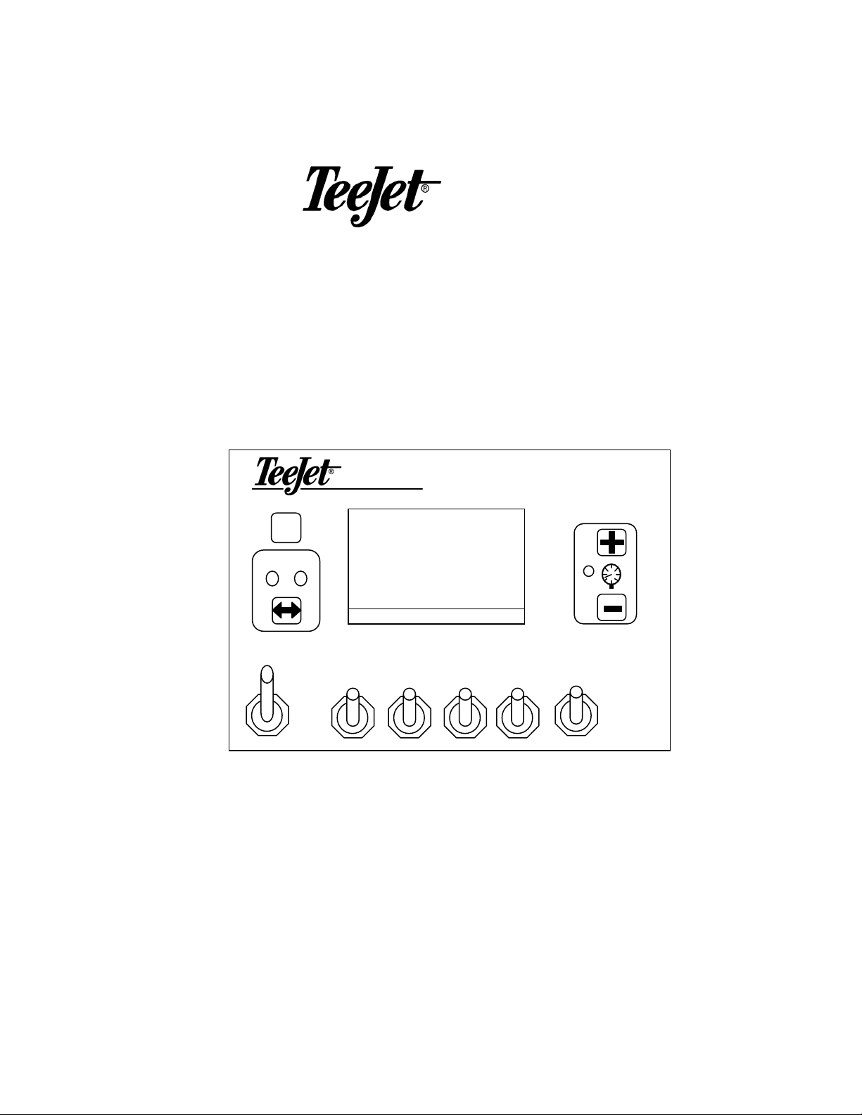
844-RA
844-R
A
Auto Man
Sprayer Control
1 2 3 4 5
P
RO
ROAD APPLICATION CONTROLLER

MI844-RA Programming and Operating Manual, 01/2000 2 of 28
Table Of Contents
TABLE OF CONTENTS ............................................................................................................................. 2
PROGRAMMING GUIDELINES.............................................................................................................. 4
IMPORTANT PRELIMINARY INFORMATION .................................................................................................. 4
POWERING CONSOLE ON/OFF ............................................................................................................. 5
POWER ON.................................................................................................................................................. 5
POWER OFF ................................................................................................................................................ 5
PROGRAMMING THE 844-RA SPRAYER CONTROL SYSTEM ...................................................... 6
SELECTION OF WORKING UNITS ................................................................................................................ 6
Reset To Defaults .................................................................................................................................. 6
SPEED SENSOR CALIBRATION..................................................................................................................... 7
Proximity/Magnetic Pulses ................................................................................................................... 7
Radar Speed Pulses............................................................................................................................... 8
DISTANCE COUNTER .................................................................................................................................. 9
FLOW METER SENSOR INSTALLED?............................................................................................................ 9
FLOW METER PULSES............................................................................................................................... 10
Manual Entry ...................................................................................................................................... 10
Automatic Calibration ........................................................................................................................ 10
PRESSURE SENSOR INSTALLED? ............................................................................................................... 11
PRESSURE TRANSDUCER LOW PRESSURE CALIBRATION (P REF) .............................................................. 12
PRESSURE TRANSDUCER MAXIMUM RATING (P HI) ................................................................................. 13
SENSOR SELECTION .................................................................................................................................. 13
SECTION WIDTH ....................................................................................................................................... 14
REFERENCE PRESSURE ............................................................................................................................. 14
REFERENCE SECTION FLOW ..................................................................................................................... 15
PRESSURE REGULATING MODE ................................................................................................................ 16
REGULATING VALVE CAPACITY............................................................................................................... 17
REGULATING VALVE SPEED FACTOR ....................................................................................................... 17
Coarse Adjustment.............................................................................................................................. 17
Fine Adjustment .................................................................................................................................. 18
COMMUNICATIONS ................................................................................................................................... 18
SIMULATED GROUND SPEED .................................................................................................................... 19
Low Speed........................................................................................................................................... 19
High Speed.......................................................................................................................................... 19
MEMORY LOAD FUNCTION....................................................................................................................... 20
TARGET APPLICATION RATE ............................................................................................................ 21
OPERATING INSTRUCTIONS............................................................................................................... 22
SPRAYER CHECKOUT................................................................................................................................ 22
THE SPRAYING OPERATION ...................................................................................................................... 24
FEATURES................................................................................................................................................. 25
AREA/VOLUME DISPLAY .......................................................................................................................... 25
APPLICATION ALARM............................................................................................................................... 26
NO FLOW ALARM..................................................................................................................................... 26
BOOST MODE ........................................................................................................................................... 27
Boost Up ............................................................................................................................................. 27
Boost Down......................................................................................................................................... 27
AUTO POWER DOWN ................................................................................................................................ 28

MI844-RA Programming and Operating Manual, 01/2000 3 of 28
PRINTING.................................................................................................................................................. 28

MI844-RA Programming and Operating Manual, 01/2000 4 of 28
Programming Guidelines
Make sure that all hardware components are properly installed and tested.
Before you start the programming process you should first check if the console
and all sensors are working properly. Refer to the plumbing and installation
manual supplied with this console.
IMPORTANT PRELIMINARY INFORMATION
Before you begin, we recommend that you review the following Programming
Guidelines that control the programming process:
☛To enter the program mode press and hold the P
RO key for 3 seconds. The
master switch must be in the off position.
☛To exit the program mode press and hold the P
RO key for 3 seconds, your
inputs will be stored and the computer will exit the program mode. This action
will not be necessary until the last programming step has been completed.
☛To increase the value of a programmable digit, press the +key. To decrease
the value, press the key. These keys are located directly to the right of the
display. For some programming steps, pressing and holding the +or key
will change the programmable value rapidly. Pressing the +or key once
will change the value by one increment.
☛Pressing the +and keys simultaneously in some programming steps will
set the value to “0” or will start an automatic calibration.
☛Pressing the key in some steps will reset the value to the factory default
value.
☛Pressing the P
RO key will advance you to the next programming step. After the
last programming step, the console will return to the first programming step.
☛Note: Due to differences in fonts, some letters on the displays shown in
this manual are not identical with the corresponding letters on the
display of the controller. We tried to match them as close as possible.

MI844-RA Programming and Operating Manual, 01/2000 5 of 28
G5 1
0 0 2 5
1.0 3
s f t
ROAD
A
PPLICATION CONTROLLER
ROAD APPLICATION CONTROLLER
Powering Console On/Off
POWER ON
After all the necessary electrical connections
have been made (refer to the Plumbing and
Installation manual included with this kit) the
console is ready to be powered on. To power
the 844-RA on press the P
RO key once. Initially
the console will display the software version
of the console in the top display and the serial
number of the console in the bottom of the
display for approximately 5 seconds. This
information will be needed when calling for
support. After 5 seconds the display will show
the normal operating view.
POWER OFF
To manually power the console off, press
the and P
RO keys simultaneously. The
console will then save any new information
(area and volume counters) to memory and
will power off.
Note: The console also has an Auto Power Down feature. Refer to this in
the features section of this manual.
MI844-RA Programming and Operating Manual, 01/2000 6 of 28
u n i t
g l n
P
RO
ROAD APPLICATION CONTROLLER
g p a
d f l t
y e s
r e s
P
RO
ROAD APPLICATION CONTROLLER
Programming the 844-RA Sprayer Control System
To enter the Program Mode, press and hold the P
RO key for 3 seconds. The first
programming step should appear on the display.
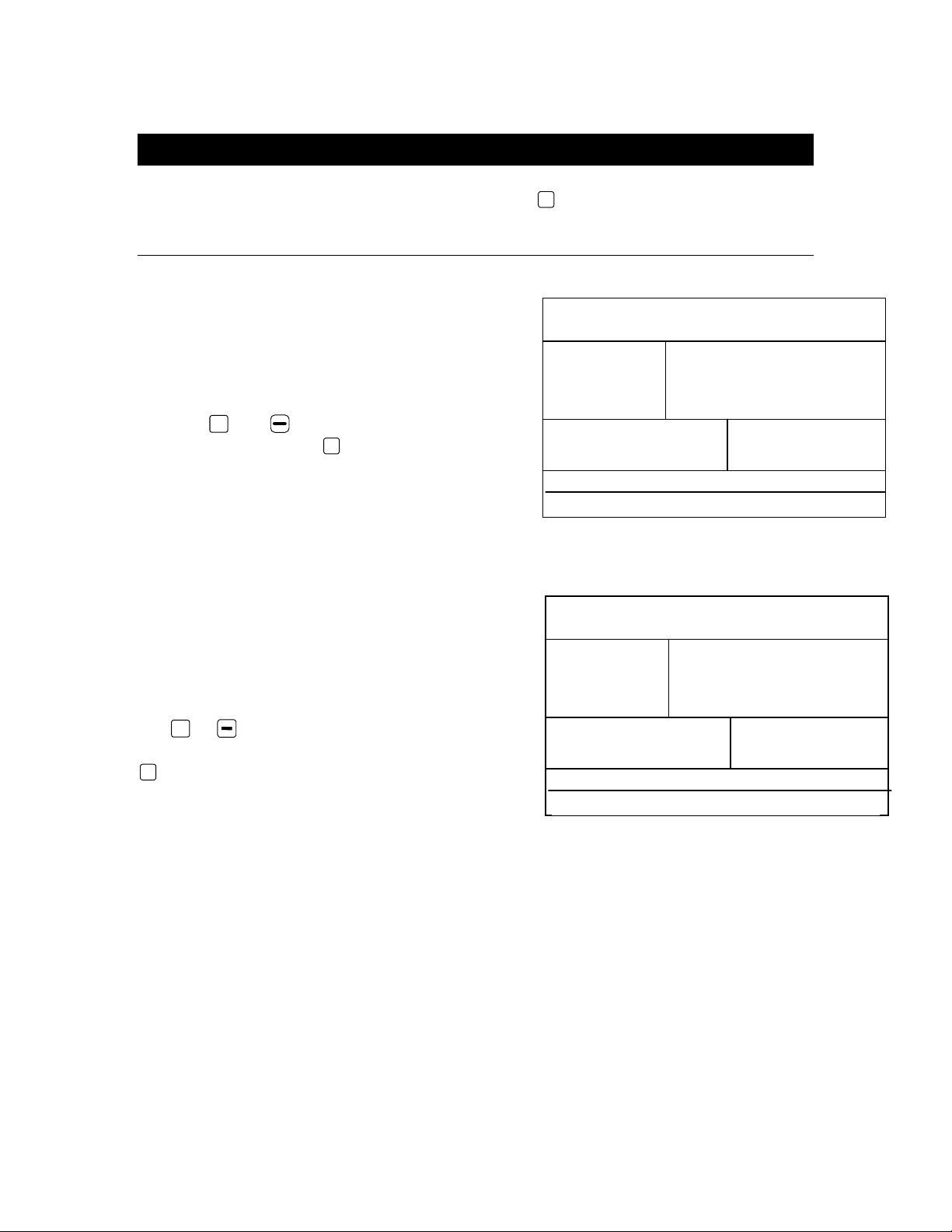
SELECTION OF WORKING UNITS
The 844-RA is capable of working in either
GLM (Gallons Per Lane Mile) or GPA (Gallons
Per Acre) units. In this step you select which
units you will be using.
Use the +and keys to switch from GLM to
GPA units. Press the P
RO key to accept the
value and advance to the next program step.
Reset To Defaults
If you made a change to the units in the first
programming step, before advancing to the
next step the console will ask if you would like
to reset all the program parameters to defaults
specified for the units you have chosen. Use
the +or key to select either yes or no.
After you have made your selection, press the
P
RO key to begin resetting or advance to the next
step.
Note: If you did not make any changes to the units, this step will be
skipped and you will automatically be advanced to Speed Sensor
Calibration Step.

MI844-RA Programming and Operating Manual, 01/2000 7 of 28
2 5 0
c a l
s p d
P
RO
ROAD APPLICATION CONTROLLER
c a l
P
RO
ROAD APPLICATION CONTROLLER
15 7
c a l
s p d
P
RO
ROAD APPLICATION CONTROLLER
SPEED SENSOR CALIBRATION
Note: During Speed Calibration, the 844-RA will automatically sense
whether a Wheel Speed or Radar Speed Sensor is being used.
Proximity/Magnetic Pulses
The speed sensor needs to be calibrated in
order to provide the proper speed and area
readings. The value for this step is the
number of pulses generated by the speed
sensor in 300 ft., or by entering the number
manually.
Automatic Calibration:
To automatically calibrate the speed sensor,
first mark off a distance of exactly 300 ft.
Next press and hold the +and keys
simultaneously for 3 seconds to clear the
contents of the display and to activate the
auto calibration mode. When the auto
calibration mode has been activated, “CA L ”
will be displayed at the lower right of the
display.
Now start driving toward the start point of the
of 300 ft. (100 meter) course. As you cross
the start point press the +key once to begin
the calibration process. Continue across the
course and the 844-RA will count the pulses
as the sprayer moves. The speed at which
you drive over the course is not important. As
you cross the end point, press the +key
once. The number displayed is your speed
calibration number.
Note: The auto speed calibration process should take place with the
sprayer tank ½ full.
Note: It is best to repeat the automatic speed calibration process at least
twice and use and average of the speed calibration numbers.

MI844-RA Programming and Operating Manual, 01/2000 8 of 28
r a d
118
c a l
s p d
P
RO
ROAD APPLICATION CONTROLLER
During the automatic calibration step, the 844-RA automatically senses whether
a proximity/magnetic or radar ground speed sensor is installed
Radar Speed Pulses
Automatic Calibration
The automatic calibration of a Radar speed
sensor is similar to the automatic calibration of a
proximity/magnetic wheel speed sensor. Refer
to the directions above. When the console has
determined that a Radar Speed Sensor is being
used, “RAD” will be displayed in the lower left of
the console display.
When the correct value has been entered, press the P
RO key to validate this value
and advance to the next step.
Note: If the auto calibration mode has been activated, no other functions
are possible until the console receives speed pulses for calibration. To
deactivate the auto calibration mode, press the +key twice.
Note: To manually enter the radar calibration value, first press the P
RO and +
keys simultaneously to put the console into radar mode. When the control
console is in the radar mode, “RA D” will be displayed in the lower left of the
console display. Now use the +or keys to adjust the value. Pressing the
Auto/Man key will reset the speed calibration to the default value.

MI844-RA Programming and Operating Manual, 01/2000 9 of 28
c t r
0
f t
d s t
P
RO
ROAD APPLICATION CONTROLLER
f l o
s e n s
y e s
P
RO
ROAD APPLICATION CONTROLLER
DISTANCE COUNTER
This step is a feature, not a calibration step. No
specific value needs to be entered here for the
controller to operate correctly.
This feature will measure distance in feet. This
can be used to confirm Automatic Speed
Calibration (see note below). To activate the
counter, turn the Master Boom Switch on. To
avoid actually spraying during this task, toggle
the individual boom sections off.
Anytime that the Master Boom Switch is on during this step to console will
measure distance. If the Master switch is toggled off, the console will stop
counting distance.
To clear an existing distance, press and hold the +and keys simultaneously
for 3 seconds.
Note: To confirm Automatic Speed Calibration, first complete the
calibration procedure. Advance to Distance Counter step. Drive across the
same 300 feet course turning the Master Switch ON at the start point and
OFF at the finish point. Distance measured should be 300 feet (+/- 6 feet).
FLOW METER SENSOR INSTALLED?
This step indicates if a flow meter has been
installed on the sprayer. Use the +or
keys to adjust the value. Either select YES if a
flow meter is installed or NO if a flow meter will
not be used.
When the correct value has been entered,
press the P
RO key to validate this value and
advance to the next step.
Note: If you select NO in this step, the next step in the manual will not
appear in the console programming selection.
MI844-RA Programming and Operating Manual, 01/2000 10 of 28
p l s
6 5 0 .0
c a l
f l o
P
RO
ROAD APPLICATION CONTROLLER
c a l
P
RO
ROAD APPLICATION CONTROLLER
2 3
2 7 7 7
c a l
P
RO
ROAD APPLICATION CONTROLLER
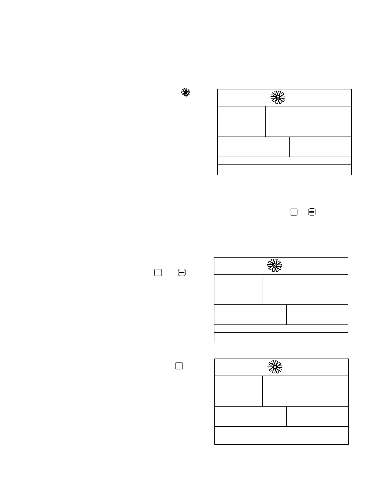
FLOW METER PULSES
Note: This step may not appear in the console programming. It only
appears if the Flow Meter Installed step is set to YES.
During the Flow Meter Pulses step, the
symbol (flow meter turbine) will be flashing at
the top of the console display.
In this step the flow meter calibration number
can be entered manually from the factory
calibrated flow meter pulse rate tag or an Auto
calibration procedure can be activated to
determine the flow meter pulses based on a
know volume of fluid.
Manual Entry
First locate the factory calibrated flow meter pulse rate tag on the flow meter. If
this varies from the default value (it usually does) of the console, use the +or
keys to modify the value.
Automatic Calibration
To complete an automatic calibration of the
flow meter, press and hold the +and keys
simultaneously for 3 seconds. This will clear
the existing value and initiate the calibration
procedure.
“CA L ” will be displayed in the screen. This
indicates that the controller is ready to begin
the calibration process.
Engage the sprayer pump. Push the +key to
activate the calibration. Now turn the boom
sections on and begin spraying a known
volume of fluid (e.g. 100 gallons). As you spray
the known amount, the console will count the
pulses.

MI844-RA Programming and Operating Manual, 01/2000 11 of 28
g a l
V
ol
10 0
P
RO
ROAD APPLICATION CONTROLLER
p l s
6 2 5
c a l
f l o
P
RO
ROAD APPLICATION CONTROLLER
PRS
s e n s
n o
P
RO
ROAD APPLICATION CONTROLLER
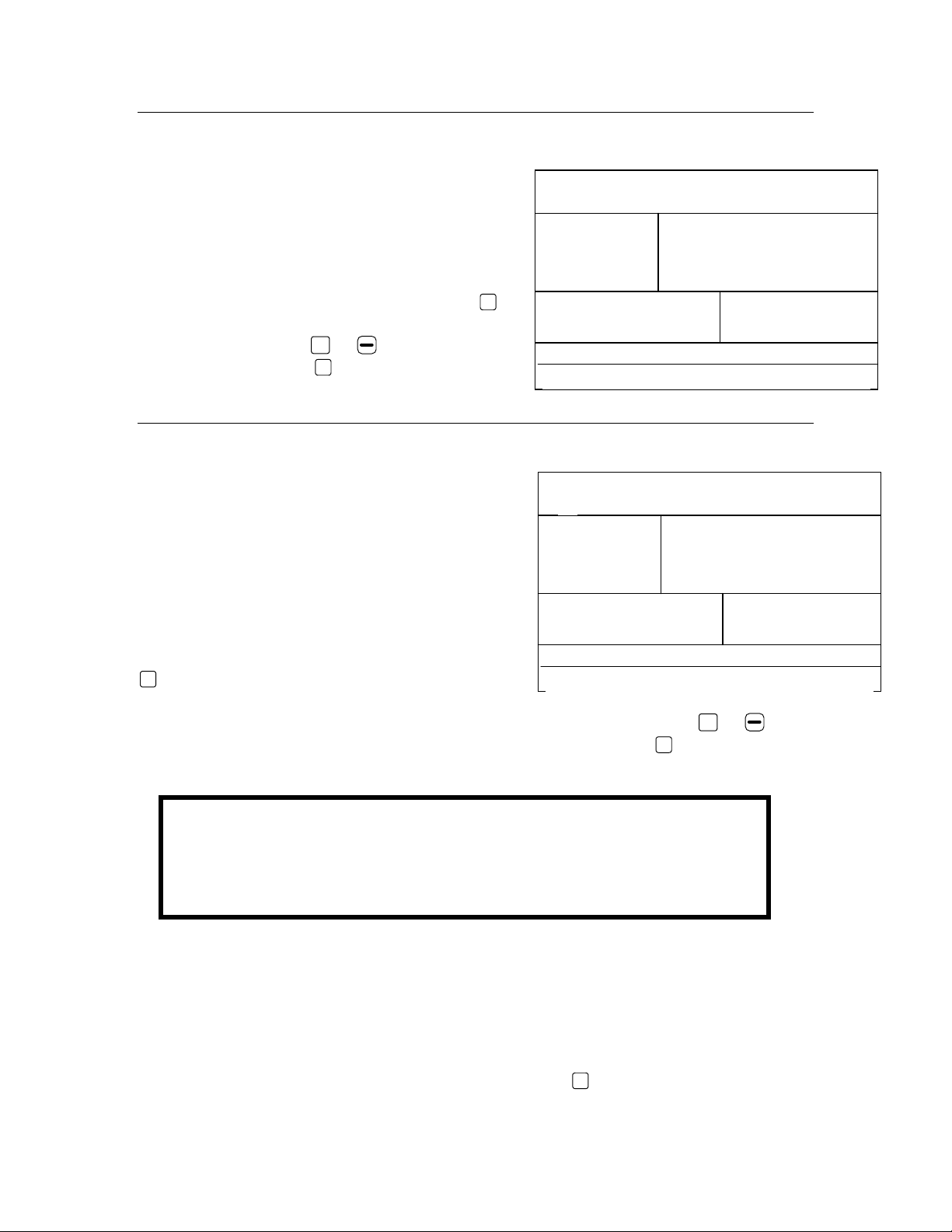
After the known volume has been sprayed out,
turn the Master switch off to stop counting
pulses.
Now press the P
RO key. The console will now
ask what volume was sprayed.
Use the +and/or keys to adjust the value to
match the volume sprayed (in gallons).
Now press the P
RO key to return to the
programming mode. Your new flow meter
calibration number will be displayed. To accept
this value press the P
RO to advance to the next
step. If you wish to repeat the calibration
procedure refer to the steps above.
Note: To achieve an accurate flow meter
calibration, a volume of at least 50 gallons
should be sprayed during calibration. The
more volume used for calibration the more
accurate the flow meter will be.
PRESSURE SENSOR INSTALLED?
This step indicates if a pressure sensor has
been installed on the sprayer. Use the +or
keys to adjust the value. Either select YES if a
pressure transducer is installed or NO if no
pressure transducer will be used.
When the correct value has been entered,
press the P
RO key to validate this value and
advance to the next step.
Note: If you select NO in this step, the next
2 steps in the manual will not appear in the
console programming selection.

MI844-RA Programming and Operating Manual, 01/2000 12 of 28
r e f
n a
4 .0 8
0
P
RO
ROAD APPLICATION CONTROLLER
r e f
s e n s
4 .0 0
PSI
0
P
RO
ROAD APPLICATION CONTROLLER
10
5 2
4 .0 0
0
P
RO
ROAD APPLICATION CONTROLLER
PRESSURE TRANSDUCER LOW PRESSURE CALIBRATION (P REF)
This step is used to calibrate the “0” pressure
setting of the pressure transducer installed in
your system. The pressure transducer used with
the 844-RA is a current type transducer and uses
a 4-20 mA reading. 4.0 mA represents 0
pressure.
This step uses an auto-calibration feature to
calibrate the transducer. Make sure that the
sprayer pump is turned off and there is
absolutely no pressure in the system (release
pressure held by boom control valves and nozzle
body check valves). In some cases it may be
best to remove the sensor from the plumbing
system to complete the calibration. Press and
hold the +and keys simultaneously for 3
seconds to activate the auto-calibration feature.
The lower left portion of the display will count 1-
10 during the calibration.
When the display finishes counting, a number
close to 4.0 (+/- 0.2) should be displayed. The
low
pressure value of the transducer is now
calibrated.
Press the P
RO key to advance to the next step.
MI844-RA Programming and Operating Manual, 01/2000 13 of 28
p r s
s e n s
p h i
PSI
14 5
P
RO
ROAD APPLICATION CONTROLLER
f l o
r e g
P
RO
ROAD APPLICATION CONTROLLER
PRESSURE TRANSDUCER MAXIMUM RATING (P HI)
This step is used to set the maximum rating
of the pressure transducer in your system.
This number can be found stamped on the
pressure transducer itself. If your transducer
has a maximum rating of 145 psi (10 bar) and
that number is shown in the display, then
advance to the next step by pressing the P
RO
key. If however, the maximum rating is 363
psi (25 bar), use the +or keys to change
the value. Press the P
RO key to advance to the
next step.
SENSOR SELECTION
The 844-RA system can be used with either a
flow meter, pressure transducer or both. This
step tells the computer which sensor you will
be using on your sprayer to control the
regulation.
The default value is set for a “F L O” based
system using a flow meter. If this is what you
have installed on your sprayer, then press the
P
RO key to advance to the next step.
If however you have installed a pressure transducer instead, us the +or key
to select “PRS” for a pressure based system. Then press the P
RO key to advance
to the next step.
If both sensors have been installed on the sprayer, this step will determine which
sensor will be used by the 844-RA to determine regulation. If “F L O” is selected,
the flow meter will be used to control flow and the pressure transducer will be
used only to display the actual pressure. If “PRS” is selected, the pressure
transducer will be used to control the flow and display the actual pressure.
Select the appropriate sensor setting then press the P
RO key to accept the value
and advance to the next programming step.
Warning
The pressure based regulation may only be used when you are
using linear tips. For non-linear tips you should always use flow
based regulation. Most tips are linear and may be used with
Pressure Based re
g
ulation
,
but ConeJet ti
p
s are non-linear.

MI844-RA Programming and Operating Manual, 01/2000 14 of 28
ROAD APPLICATION CONTROLLER
5
i n c h
12 0
s e c
P
RO
ROAD APPLICATION CONTROLLER
PRS
4 0 .0
REF
P
RO
ROAD APPLICATION CONTROLLER
1
i n c h
12 0
s e c
P
RO
SECTION WIDTH
The 844-RA can control up to 5 boom sections
individually. The next 5 programming steps
indicate the width of each individual section.
Use the +or keys to adjust the value so
that it matches the width of boom section 1 in
inches. Then press the P
RO key to advance to
section 2.
Repeat this procedure until all 5 boom
sections have been programmed. Any
individual boom switches not being used for a
boom section must be programmed to a “0”
value.
After programming the boom section width for
section switch 5, press the P
RO key to advance
to the next step.
REFERENCE PRESSURE
In the following programming steps, reference
flow rates must be entered for each boom
section. Those flows must be referenced at a
specific reference pressure. Select a pressure
that you will use to reference the flow rates
and enter that pressure here.
Use the +and keys to adjust the value.
Press the P
RO key to advance to the next step.

MI844-RA Programming and Operating Manual, 01/2000 15 of 28
ROAD APPLICATION CONTROLLER
1
2 .4 0
g p n
s e c
P
RO
ROAD APPLICATION CONTROLLER
5
2 .4 0
g p n
s e c
P
RO
REFERENCE SECTION FLOW
In this step you must enter the reference flow
for boom section 1 in GPM. This is the total
flow rate for the boom section if it were
spraying at the reference pressure indicated in
the previous step.
To find the total flow rate for a boom section,
add all of the individual tip flow rates at the
referenced pressure.
Use the +or key to adjust the value to
match the actual flow rate.
After you have entered the flow rate for section
1 press the P
RO key to advance to section 2 flow
rate. Repeat the procedure above until all 5
boom section reference flow rates have been
entered.
Note: Any individual boom section not
being used must be programmed to a “0”
value.
When you have programmed and validated the
last Reference Section Flow press the P
RO key to
advance to the next programming step.
BOOM SECTION 1 BOOM SECTION 3BOOM SECTION 2
1 2 3 11
24 3
32 4
Boom Section 1
4 Tips – XR8006VS
(1) XR8006VS = 0.60 GPM
@40 PSI
4 X 0.60 = 2.40 GPM @40PSI
Boom Section 2
3 Tips – XR8006VS
(1) XR8006VS = 0.60 GPM
@40 PSI
3 X 0.60 = 1.80 GPM @40PSI
Reference Section Flow Exam
p
le

MI844-RA Programming and Operating Manual, 01/2000 16 of 28
ROAD APPLICATION CONTROLLER
b y p
r e g
P
RO
ROAD APPLICATION CONTROLLER
t h r
r e g
P
RO
PRESSURE REGULATING MODE
This step tells the 844-RA where the regulating
valve has been plumbed. Once set correctly,
this value should not change unless the
regulating valve is physically moved to a new
point in the plumbing. For more information
about plumbing refer to the Plumbing and
Installation manual supplied with this kit.
The default value “BYP” indicates that the
pressure regulating valve is plumbed in a
bypass line. If this is correct press the P
RO key to
accept the value and advance to the next step.
If you have plumbed the pressure regulating
valve in a supply line to the booms, this is
considered a throttling position. If you have
located your regulating valve in this position,
use the +or key to change the value to
“thr” (throttling mode). By doing this, you have
reversed the polarity that the console uses to
control the regulating valve.
Press the P
RO key to advance to the next step.
Note: When programmed in the bypass
mode, with the controller in “MAN” mode,
the pressure regulating valve should close
when the +key is pressed and open
when the key is pressed.
Note: When programmed in the throttling
mode with the controller in “MAN” mode,
the valve should open when the +key is
pressed and close when the is pressed.

MI844-RA Programming and Operating Manual, 01/2000 17 of 28
ROAD APPLICATION CONTROLLER
c a p
3 2
g p n
r e g
P
RO
ROAD APPLICATION CONTROLLER
s p d
r e g
P
RO
1o .2
Common TeeJet Regulating Valves
344AE-2RL .................... 27 GPM
344AE-2RB .................... 30 GPM
344AE-2PR .................... 12 GPM
AA346ZR ....................... 85 GPM
AA346ZRB..................... 85 GPM
REGULATING VALVE CAPACITY
Enter the maximum flow capacity of the
regulating valve you are using in Gallons Per
Minute (GPM). The regulating parameters
needed to drive the regulating valve smoothly
are different depending on the size of the
valve. This step optimizes these parameters of
the 844-RA for the size of valve you are using.
Use the +or keys to adjust the value so
that it matches the maximum flow capacity
(GPM) of the regulating valve you are using.
Note: Reference the valve manufacturer’s
literature to determine the flow capacity of
the regulating valve.
Press the P
RO key to advance to the next step.
REGULATING VALVE SPEED FACTOR
This step allows you to adjust the speed of the pressure regulating valve to
accommodate different application needs. Operating conditions may necessitate
a higher or lower response speed for the regulating valve. This is accomplished
by adjusting both the coarse and fine adjustment values.
Coarse Adjustment
The coarse adjustment controls the speed of
the valve when large adjustments in flow are
required by the controller. To change the
response time number, simply use the +or
keys to increase or decrease the number. Any
number between 0 and 19 may be selected.
0 = Slow : 19 = Fast
If your regulating valve is plumbed in a by-pass
line, the valve speed coarse adjustment number
of 15 works very well in most applications.

MI844-RA Programming and Operating Manual, 01/2000 18 of 28
ROAD APPLICATION CONTROLLER
s p d
r e g
P
RO
1o .2
ROAD APPLICATION CONTROLLER
c o n
n o
P
RO
If your regulating valve is plumbed in the throttling position (supply line), start with
a valve coarse adjustment speed number of 5 and adjust the number according
to your application requirements.
Press the P
RO key to accept the value and advance to the Fine Adjustment setting.
Fine Adjustment
The fine adjustment controls the speed of the
valve when small adjustments in flow are
required by the controller. To change the
response time number, simply use the +or
keys to increase or decrease the number. Any
number between 0 and 9 may be selected.
0 = Slow : 9 = Fast
It is recommended that you start with a fine
adjustment speed of 2. This works well in most
situations. This number may need to be
optimized during the spraying operation.
Note: Adjusting agitation volumes can often assist the regulating valve
operation.
To accept your Regulating Valve Actuating Factor and advance to the next step,
press the P
RO key.
Note: This speed value can be adjusted to optimize system performance.
If you notice that the valve seems to “search” for the programmed
application rate by cycling the pressure up and down continuously, reduce
the number until the “searching” is minimized or eliminated. Conversely, a
higher number will increase the valve response speed and speed up the
rate of adjustment.
COMMUNICATIONS
If your 844-RA has been upgraded to be
communications compatible, this step lets
you select what type of communication you
will be using. The choices available are
the default of “n o c o n ” (no
communications), ”c n t p r t ”
(Contractor printing), “u s r p r t ” (User
printing), “g p s ” (Global Positioning
System communication capability), “l o g ”

MI844-RA Programming and Operating Manual, 01/2000 19 of 28
MPH
2 0 .0
l o
s p d
s i n
P
RO
ROAD APPLICATION CONTROLLER
MPH
3 0 .0
h i g h
s p d
s i n
P
RO
ROAD APPLICATION CONTROLLER
(Downloading to a PC on the go capability), or “p c ” ( PC link – not used).
If, however, your 844-RA has been upgraded with the communications package,
use the +and keys to select the type of communication you will be using.
After selecting the communication you will be using, press the P
RO key to advance
to the next step.
SIMULATED GROUND SPEED
Simulated ground speed allows you to check out the functions and operations of
the console and of the sprayer, spraying water, without actually moving the
sprayer. This can and should be done prior to any spraying activity.
The 844-RA has a low and high simulated ground speed. This allows you to
switch between the two to simulate a speed change to ensure the console is
regulating properly during the Sprayer Checkout.
Low Speed
To set the Low simulated speed use the +
and keys to adjust the value.
When the low value has been set, press the P
RO
key to advance to the High Simulated speed
step.
High Speed
To set the High simulated speed use the +
and keys to adjust the value.
When the high value has been set, press the P
RO
key to advance to the next programming step.
To activate the simulated speed, while in the normal operating mode with the
master switch ON, press the P
RO and keys for low simulated speed; press the P
RO
and +keys for high simulated speed. The simulated speed will remain in the
normal operating mode display until the console receives actual speed pulses.

MI844-RA Programming and Operating Manual, 01/2000 20 of 28
ROAD APPLICATION CONTROLLER
l o a d
n o
n e n
P
RO
Note: Once the sprayer begins moving and the 844-RA receives actual
speed pulses, the simulated speed feature is deactivated. If you are using
a Radar Speed Sensor, disconnect the Radar connection from the main
console. Because of the sensitivity of this speed sensor, any movement
can disable simulated speed.
MEMORY LOAD FUNCTION
The memory load function is used to restore all
programming values to previously set values. A
sprayer manufacturer may pre-program this
console for specific parameters on a sprayer and
save those values internally. If for some reason
you need to get back to those pre-programmed
values this step allows you to do that. Use the
+or keys to select either YES or NO.
The default NO means that your programming values will be saved as you have
entered them. The YES selection will likely change the program values. It is
recommended that you leave this setting at NO unless otherwise instructed.
Press the P
RO key to advance to the next step. This should take you to the
beginning of the program mode.
Now press and hold the P
RO key for three seconds to exit the program mode and
save the programming information to the computer’s memory.
Note: For your protection, the 844-RA console will not automatically power
down while in the Program Mode. You must exit properly as described
above to enable the console’s auto power down feature.
Note: Cutting the power to the controller while in the Program Mode will
not save any changes into the computers memory.
Table of contents
Other TeeJet Farm Equipment manuals


Popular Farm Equipment manuals by other brands

Schaffert
Schaffert Rebounder Mounting instructions

Stocks AG
Stocks AG Fan Jet Pro Plus 65 Original Operating Manual and parts list

Cumberland
Cumberland Integra Feed-Link Installation and operation manual

BROWN
BROWN BDHP-1250 Owner's/operator's manual

Molon
Molon BCS operating instructions

Vaderstad
Vaderstad Rapid Series instructions


