Limited Warranty The liability of tekmar Control Systems Ltd. and tekmar Con-
trol Systems, nc. (“tekmar”) under this warranty is limited. The purchaser, by
taking receipt of the tekmar product (“product”), acknowledges receipt of the
terms of the warranty and acknowledges that it has read and understands same.
tekmar warrants ea h tekmar produ t against defe ts in workmanship and materials,
if the produ t is installed and used in omplian e with tekmar's instru tions. The war-
ranty period is for a period of twenty-four (24) months from the produ tion date if the
produ t is not installed during that period, or twelve (12) months from the do umented
date of installation if installed within twenty-four (24) months from the produ tion date.
The liability of tekmar under this warranty shall be limited to, at tekmar's sole dis re-
tion: the ost of parts and labor provided by tekmar to repair defe ts in materials and/
or workmanship of the defe tive produ t; or to the ex hange of the defe tive produ t
for a repla ement produ t; or to the granting of redit limited to the original ost of the
defe tive produ t, and su h repair, ex hange or redit shall be the sole remedy avail-
able from tekmar, and, without limiting the foregoing in any way, tekmar is not re-
sponsible, in ontra t, tort or stri t produ t liability, for any other losses, osts, ex-
penses, in onvenien es, or damages, whether dire t, indire t, spe ial, se ondary,
in idental or onsequential, arising from ownership or use of the produ t, or from
defe ts in workmanship or materials, in luding any liability for fundamental brea h of
ontra t.
This warranty applies only to those products returned to tekmar during the
warranty period. This warranty does not cover the cost of the parts or labor to
remove or transport the defective product, or to reinstall the repaired or re-
placement product. Returned products that are not defective are not covered
by this warranty.
This warranty does not apply if the product has been damaged by negligence
by persons other than tekmar, accident, fire, Act of God, abuse or misuse; or
has been damaged by modifications, alterations or attachments made subse-
quent to purchase which have not been authorized by tekmar; or if the product
was not installed in compliance with tekmar’s instructions and the local codes
and ordinances; or if due to defective installation of the product; or if the prod-
uct was not used in compliance with tekmar’s instructions.
This warranty is in lieu of all other warranties, express or implied, which the
Governing Law (being the law of British Columbia) allows parties to contractu-
ally exclude, including, without limitation, warranties of merchantability,
fitness for a particular purpose, durability or description of the product, its non-
infringement of any relevant patents or trademarks, and its compliance with or
non-violation of any applicable environmental, health or safety legislation; the
term of any other warranty not hereby contractually excluded is limited such
that it shall not extend beyond twenty-four (24) months from the production
date, to the extent that such limitation is allowed by the Governing Law.
Product Return Procedure Produ ts that are believed to have defe ts in workman-
ship or materials must be returned, together with a written des ription of the defe t, to
the tekmar representative for that territory. If the address of the representative is not
known, please request it from tekmar at the telephone number listed below.
Control Systems
tekmar Control Systems Ltd., Canada
tekmar Control Systems, In ., U.S.A.
Head Office: 4611 - 23rd Street
Vernon, B.C. Canada V1T 4K7
Tel. (250) 545-7749 ax. (250) 545-0650
Web Site: www.tekmarcontrols.com
Produ t design, software and literature are Copyright © 2000 by:
tekmar Control Systems Ltd. and tekmar Control Systems, In .
All spe ifi ations are subje t to hange without noti e.
Printed in Canada. D 060 -09/00.
2 of 2
Setting a Minimum Temperature Limit
Remove one of the limit pins and re-insert it into the hole that is slightly to the left of the post at
the bottom of the dial. With the pin in pla e the dial should only rotate lo kwise from its urrent
position as the ounter- lo kwise rotation is now restri ted by the pin.
Setting a Maximum Temperature Limit
Insert one of the pins into the hole that is slightly to the right of the post.
Setting a ixed Temperature
Insert one of the pins into the hole in the bottom of the dial su h that the pin enters the post behind
the dial. With the pin in pla e the dial should be fixed in position.
Repla e the s ale by sliding it onto the dial until the re tangular hole slips into the holding lip.
Repla e the front over by following Step Four of the Installation pro edure.
Overrides
OVERRIDES
The 060 RTU allows the user to override the zone’s s hedule by using the push button on the fa e of the RTU.
Temporary Occupied (Three Hours)
If the push button on the fa e of the RTU is pressed and held for more than one se ond, the zone will enter into a temporary o upied
override. The LED will turn green and the zone will operate at the o upied temperature for the next three hours.
Permanent UnOccupied
If the push button on the fa e of the RTU is pressed and released, the zone will enter into a permanent uno upied override. The LED
will turn red and the zone will operate at the uno upied temperature until the override is an elled.
To an el an override, press and release the push button. The LED will turn off.
Specifications
Post
Dial
To set the low
temperature limit, insert
a pin slightly to the left of
the post
Holding Clip
Limited Warranty and Product Return Procedure
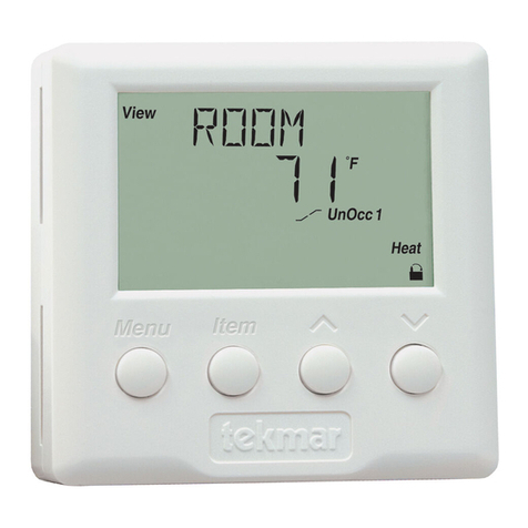
Room Temperature Unit (RTU) 060
Literature — D 060
Pa kaged weight — 0.16 lb. (72 g), En losure G, white PVC plasti
Dimensions — 2-7/8” H x 2-7/8” W x 13/16” D (73 x 73 x 21 mm)
Approvals — CSA C US
Ambient onditions — Indoor use only, 15 to 120°F (-10 to 50°C), non- ondensing.
Power supply — tekmar ontrol; tekmar Net™ 1 (tN1)
Sensor — NTC thermistor, 10 kΩ @ 77°F (25°C ±0.2°C) ß=3892
Setpoint range — 40 to 100°F (4 to 38°C)
70


