Tekram Technology P5T30-B4 User manual

P5T30-B4 MAINBOARD
User’s Manual
Rev: 1.05
Date: January - 98
* All other product names are trademarks or copyrights of their respective owners.


FCC Compliance StatementFCC Compliance Statement
P5T30-B4 User’s Manual 1
FCC Compliance Statement
This device complies with Part 15 of the FCC rules, operation is subject to the following
two conditions.
1. This device may not cause harmful interference and,
2. This device must accept any interference received, including interference that may cause
undesired operation.
This equipment has been tested and found to comply with limits for a Class B digital
device, pursuant to Part 15 of the FCC rules. These limits are designed to provide
reasonable protection against harmful interference in residential installations. This
equipment generates, uses, and can radiate radio frequency energy, and if not installed and
used in accordance with the instructions, may cause harmful interface to radio
communications. However, there is no guarantee that interference will not occur in a
particular installation. If this equipment does cause interference to radio or television
equipment reception, which can be determined by turning the equipment off and on, the
user is encouraged to try to correct the interference by one or more of the following
measures:
lReorient or relocate the receiving antenna.
lMove the equipment away from the receiver.
lPlug the equipment into an outlet on a circuit different from that to which the receiver is
connected.
lConsult the dealer or an experienced radio/television technician for additional
suggestions.
The FCC requires the user to be notified that any change or modifications to the equipment
by the user not expressly approved by the grantee or manufacturer could void the user’s
authority to operate such equipment. The use of shielded cables for connection of the
monitor to the graphics card is required to assure compliance with FCC regulations.

Table of ContentsTable of Contents
P5T30-B4 User’s Manual
2
INTRODUCTION.................................................................................4
Product Description .......................................................................................... 4
Item Checklist .................................................................................................. 4
Features ............................................................................................................ 5
BOARD LEVEL FEATURES ..............................................................6
INSTALLING THE CPU AND MEMORY.........................................9
Static Precautions.............................................................................................. 9
Installing the CPU............................................................................................. 9
Connecting the CPU Cooling Fan ..................................................................... 9
Setting the CPU Clock Selection Jumper........................................................... 10
Setting the CPU Voltage Selection Jumper........................................................ 11
Installing the Memory (DRAM SIMM/DIMMs)................................................ 12
The Level-2 Cache (SRAM).............................................................................. 12
SETTING THE JUMPERS ..................................................................13
CONNECTIONS...................................................................................15
Power Supply Cables......................................................................................... 15
Serial and Parallel Ports.................................................................................... 15
IrDA-compliant infrared module connector....................................................... 15
USB Connection................................................................................................ 15
Keyboard Connector.......................................................................................... 16
PS/2 Mouse Connector...................................................................................... 16
Floppy Drives.................................................................................................... 16
IDE Hard Drives and CD-ROMs....................................................................... 16
MAINBOARD BIOS SETUP................................................................17
About the BIOS................................................................................................. 17
Using Setup....................................................................................................... 17

Table of ContentsTable of Contents
P5T30-B4 User’s Manual 3
Getting Help...................................................................................................... 17
A Final Note About Setup ................................................................................. 17
MAIN MENU ................................................................................................... 18
STANDARD CMOS SETUP............................................................................. 19
BIOS FEATURES SETUP ................................................................................ 22
CHIPSET FEATURES SETUP ......................................................................... 25
POWER MANAGEMENT SETUP ................................................................... 28
PNP/PCI CONFIGURATION SETUP............................................................... 30
LOAD BIOS DEFAULTS................................................................................. 32
LOAD SETUP DEFAULTS.............................................................................. 32
INTEGRATED PERIPHERALS........................................................................ 32
SUPERVISOR PASSWORD AND USER PASSWORD SETTING................... 34
IDE HDD AUTO DETECTION........................................................................ 35
SAVE & EXIT SETUP / EXIT WITHOUT SAVING........................................ 35
PCI Device Listing............................................................................................ 35
DESKTOP MANAGEMENT INTERFACE (DMI).............................36
FLASH BIOS PROGRAMMING UTILITY........................................37
HAREWARE MONITORING UTILITY............................................38
DC-310U PCI ULTRA-SCSI ADAPTER .............................................39
APPENDIX A Using the ATX Power Supply ......................................40

INTRODUCTIONINTRODUCTION
P5T30-B4 User’s Manual
4
Product Description
The P5T30-B4 represents the highest level of technology available in PC Mainboards
today. Designed as a flexible, high-performance and cost-effective solution for System
Integrators and End Users alike, the P5T30-B4 provides the power and expandability to
meet the requirements of the most advanced operating systems and software applications.
The P5T30-B4 is designed to provide greater overall system throughput by utilizing the
latest in I/O technology. By incorporating such advanced features as Ultra DMA/33 Bus
Mastering IDE and Universal Serial Bus (USB) onto the mainboard, optimum system
performance is assured and system design and implementation is simplified.
Fully “Plug & Play” compatible via an Award BIOS, the P5T30-B4 facilitates easy system
configuration and peripheral setup. Advanced BIOS features include Temperature
Monitoring and Alert functions designed to prevent the CPU from overheating. Also, the
Award BIOS supports ACPI Readiness and is compatible with the PC’97 specification.
With support for up to 512KB Pipelined Burst SRAM L2 cache and 256MB of EDO or
SDRAM System RAM, the P5T30-B4 is the ideal foundation for high-end computer
systems.
Item Checklist
Your mainboard package should include the items listed below. Damaged or missing items
should be reported to your vendor.
þThe P5T30-B4 mainboard
þMounting bracket with (1) COM2
serial port & (1) PS/2 connector
ribbon cable attached.
þMounting bracket with (1) parallel &
(1) serial COM1 port ribbon cables
attached.
þFloppy disk drive ribbon cable
þIDE ribbon cable
þFan adaptive cable
þThis User’s Manual
þDiskette containing support software
for updating the FLASH BIOS,
Hardware Monitoring, Bus Master
IDE drivers and TX-Patch
¨Optional Infrared Module
¨Optional USB Module

INTRODUCTIONINTRODUCTION
P5T30-B4 User’s Manual 5
Features
Processor ZIF socket 7 support INTELPentium75−200 MHz,
P55C Processor (MMX), CYRIX 6x86 ~P200+ / 6x86MX (M2)
series, AMD K5/K6 series
Chipset INTEL 430TX Chipset
BIOS Award PCI BIOS, support DMI, Green PC, Plug-and-Play, ACPI,
LS-120 120MB ATAPI F.D.D.
SymbiosSCSI BIOS to support 53C810/860Ultra SCSI
Cache Memory On board 512 KB Write-back, Pipelined Burst L2 Cache
System Memory 4×SIMM+2×DIMM MAX. 256MB
Support EDO, FPM DRAM, SDRAM module
On-board I/O
Features 1×FDC Port Connector support up to 2.88MB
3-pin CPU Fan connector
Two-way IrDA 6-pin connector to support IrDA
8-pin USB connector to support 2 USB ports
AT keyboard connector
PS/2 mouse connector
1×Parallel Port connector support ECP/EPP
2×High Speed Serial Port connector (16550)
Advanced
Features Hardware Monitoring (CPU Fan, CPU Temperature, Power
Voltage)
PCI Bus Master
IDE 2×PCI Bus Master IDE, support LBA mode, PIO mode 3,4
ULTRA 33 synchronous DMA mode
Expansion Slots 4×32-bit PCI Bus Master slots, 3×ISA 16-bit slots
CMOS Battery Coin-form replaceable battery
Form Factor ¾ Baby AT Form factor ( 10.6″by 8.7″)
Options IrDA interface kit (internal cable/bracket set and external module)
USB cable/bracket set
Accessories 5-in-1 cable set: FDD cable, PS/2 Mouse connector kit, Two Serial,
One Parallel bracket
User’s Manual, Driver/ Utility diskettes

BOARD LEVEL FEATURESBOARD LEVEL FEATURES
P5T30-B4 User’s Manual
6
1. Mainboard BIOS 12. Floppy connector
2. Keyboard BIOS 13. Printer port connector
3. ISA slots 14. Power connector
4. PCI slots 15. COM2 connector
5. CPU socket (Socket 7) 16. Supplementary ATX
6. Infrared (IR) connector power connector
7. L2 Pipeline-burst cache 17. Infrared (IR) connector
8. Intel 82430TX chipset 18. AT keyboard connector
9. DRAM SIMM/DIMM sockets 19. PS/2 mouse connector
10.
Secondary IDE connector 20. COM1 connector
11.
Primary IDE connector 21. USB connector

BOARD LEVEL FEATURESBOARD LEVEL FEATURES
P5T30-B4 User’s Manual 7
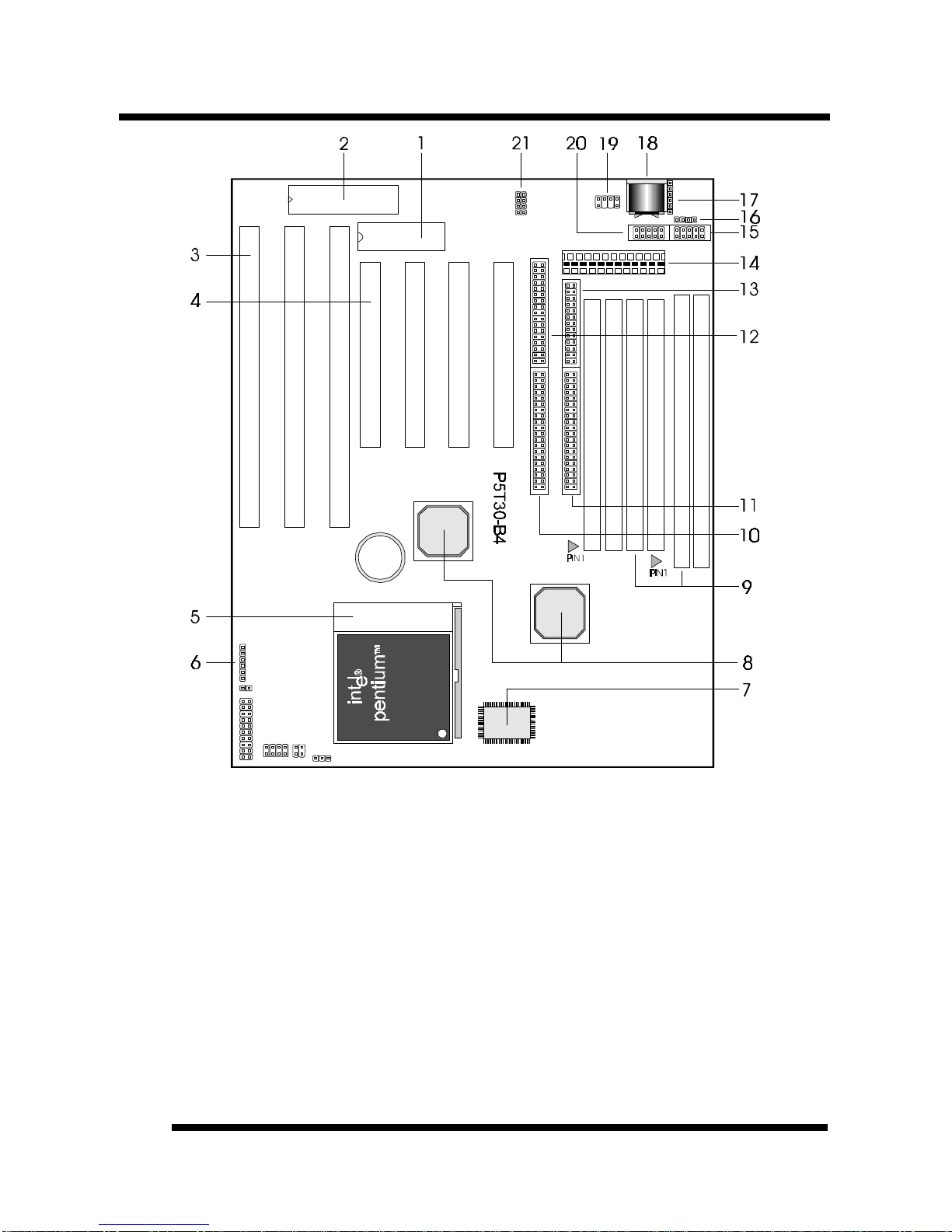
1. MAINBOARD BIOS: Award BIOS supporting “Plug and Play”, DMI, Green PC
specification, Enhanced IDE and Multi-I/O. The BIOS is FLASH Upgradeable via the
AWDFLASH Utility.
2. KEYBOARD BIOS:Firmware chip controlling keyboard operations.
3. ISA SLOTS: (3) 16-bit ISA slots
4. PCI SLOTS: (4) 32-bit PCI slots are provided.
5. CPU SOCKET: ZIF Socket 7 for Pentium CPUs. This mainboard supports CPU speeds
of 75-233MHz for Intel, AMD K5/K6 and Cyrix.
6. BACK INFRARED (IR) CONNECTOR: UART2 can also be used for the optional
Infrared Module, enabling wireless communication capability. A supplied bracket with
a single customized cable connects directly to the infrared pin-header on the mainboard.
For computer cases that support a front IR device, see number 17.
7. L2 PIPELINE-BURST CACHE: Supports Write Back Secondary Cache with 512KB
Pipeline Burst SRAM.
8. CHIPSET: Intel82430TX.
9. DRAM SIMM/DIMM SOCKETS: (4) 72-pin SIMM and (2) 168-pin DIMM sockets
are provided to support a maximum RAM memory capacity of 256 MB. SIMM/DIMM
types of either Fast Page Mode (FPM) or Extended Data Output (EDO) are supported
and automatically detected by the BIOS. SDRAM is supported on DIMM sockets.
10. SECONDARY IDE CONNECTOR: Connector for second IDE channel.
11. PRIMARY IDE CONNECTOR: Connector for first IDE channel. The on-board PCI
Bus Mastering IDE controller features support for DMA Mode 2, PIO Modes ¾, and
Ultra DMA/33 (33MB/sec) for faster data transfer rates. (2) Connectors are provided for
support of up to (4) IDE devices on two channels. Other ATAPI and Enhanced IDE
devices such as Tape Drives and CD-ROMs are also supported.
12. FLOPPY CONNECTOR: Built-in floppy controller supports (2) 5.25" or 3.5"
(1.44MB or 2.88MB) floppy drives.
13. PRINTER PORT CONNECTOR: EPP and ECP compatible parallel port.
14. POWER CONNECTOR: 12-Pin Power Connector.
15. COM2 CONNECTOR: High-speed UART compatible serial port. COM2 can be
directed to the Infrared Module for wireless connection capability.
16. SUPPLEMENTARY ATX POWER CONNECTOR: Works with the power
connector (Item 12) and the Adaptive Power Cable (optional) to support the ATX power
supply.
17. FRONT INFRARED (IR) CONNECTOR: This is convenient to system cases that
support a front IR connector.
18. AT KEYBOARD CONNECTOR: Supports IBM compatible AT style keyboards.
19. PS/2 MOUSE CONNECTOR: Supports PS/2 style mice.
20. COM1 CONNECTOR: High-speed UART compatible serial port.
21. USB CONNECTOR: A header connector for an optional USB (Universal Serial Bus)
module is provided. This connector permits the connection of two USB peripheral

BOARD LEVEL FEATURESBOARD LEVEL FEATURES
P5T30-B4 User’s Manual
8
devices directly to the port without an external hub. USB is a new technology
supporting keyboards, mouse, printers, fax modems and other telephony devices.
Comprehensive Mainboard View

INSTALLING THE CPU AND MEMORYINSTALLING THE CPU AND MEMORY
P5T30-B4 User’s Manual 9
Static Precautions
Static electricity can be a serious danger to the electronic components on this mainboard. To
avoid damage caused by electrostatic discharge, observe the following precautions:
üDon’t remove the mainboard from its anti-static packaging until you are ready to install
it into a computer case.
üBefore you handle the mainboard in any way, touch a grounded, anti-static surface, such
as an unpainted portion of the system chassis, for a few seconds to discharge any built-
up static electricity.
üHandle add-in cards and modules by the edges or mounting bracket.
Installing the CPU
üWARNING: Use of a CPU Cooling Fan to prevent CPU
from overheating is highly recommended. The Fan
should be installed first before inserting the CPU into
its socket.
1. Locate the ZIF (Zero Insertion Force) Socket 7. This
socket supports Pentium (P5) CPUs (75-233Mhz).
2. First open the socket by pulling the lever sideways,
then upwards. Notice how the lever locks in place
when pressed all the way down.
3. The CPU must be inserted with the correct orientation.
One corner of the CPU has a “notch” and looks
different that the other three. This corner is also
missing a pin unlike the other three and is marked with a white dot on top of the CPU.
Align this corner towards the end of the lever as shown in the figure below. Insert the
CPU, press it down, and close the lever until it locks into place.
Connecting the CPU Cooling Fan (J12)
This mainboard features a fan monitoring function to alert you when
the cooling fan starts to malfunction (Refer to page 27). If you are using
a fan with the standard 4-pin Molex-Type Power-Supply connector, you
should use the fan adaptive cable provided as shown:

INSTALLING THE CPU AND MEMORYINSTALLING THE CPU AND MEMORY
P5T30-B4 User’s Manual
10
Plug the Molex-Type connector of the adaptive cable to the fan’s power connector and plug
the other 3-pin Header Connector to J12, regardless of the polarity. If your Fan provides this
3-pin Header Connector, simply plug it into J12, regardless of the polarity.
Setting the CPU Clock Selection Jumper (JBF0-2 & JFS0-2)
After installing the CPU, you must set the clock selection jumper to match the frequency of
the CPU. Find the Jumper Blocks labeled JBF0-2 and JFS0-2 on the mainboard (Refer to
the diagram on page 8). Set the jumper according to the table below for your CPU
frequency.
Jumper setting for CPU:
CPU Model CPU Clock Bus Clock (JFS0-2) Ratio (JBF0-2)
Intel Pentium 233MHz 66MHz x3.5
Intel Pentium 200MHz 66MHz x3.0
Intel Pentium 166MHz 66MHz x2.5
Intel Pentium 150MHz 60MHz x2.5
Intel Pentium 133MHz 66MHz x2.0
Intel Pentium 120MHz 60MHz x2.0
Intel Pentium 100MHz 66MHz x1.5
Intel Pentium 90MHz 60MHz x1.5
Intel Pentium 75MHz 50MHz x1.5
AMD-K6-PR300 300MHz 66MHz x4.5
AMD-K6-PR266 266MHz 66MHz x4.0
AMD-K6-PR233 233MHz 66MHz x3.5
AMD-K6-PR200 200MHz 66MHz x3.0
AMD-K6-PR166 166MHz 66MHz x2.5
AMD-K5-PR200 66MHz x3.0
AMD-K5-PR166 66MHz x2.5
AMD-K5-PR150 60MHz x2.5
AMD-K5-PR133 100MHz 66MHz x1.5
AMD-K5-PR120 90MHz 60MHz x1.5
AMD-K5-PR100 100MHz 66MHz x1.5
AMD-K5-PR90 90MHz 60MHz x1.5
AMD-K5-PR75 75MHz 50MHz x1.5
Cyrix 6x86MX PR233 (M2) 188MHz 75MHz x2.5
Cyrix 6x86MX PR200 (M2) 150MHz 75MHz x2.0
Cyrix 6x86MX PR200 (M2) 166MHz 66MHz x2.5
Cyrix 6x86MX PR166 (M2) 133MHz 66MHz x2.0
Cyrix 6x86MX PR166 (M2) 150MHz 60MHz x2.5
Cyrix 6x86 P200+ 150MHz 75MHz x2.0
Cyrix 6x86 P166+ 133MHz 66MHz x2.0
Cyrix 6x86 P150+ 120MHz 60MHz x2.0
Cyrix 6x86 P133+ 110MHz 55MHz x2.0

INSTALLING THE CPU AND MEMORYINSTALLING THE CPU AND MEMORY
P5T30-B4 User’s Manual 11
Cyrix 6x86 P120+ 100MHz 50MHz x2.0
The Internal (Core) frequency corresponds to the number marked on the CPU. The External
Frequency when multiplied with the Ratio gives the CPU's internal frequency.
Bus Clock (JFS0-2): MHz Ratio (JBF0-2)
This jumper automatically sets the ISA Clock as well.
* If you are uncertain about the speed or voltage requirements of your particular CPU, you
should obtain Technical Documentation from the manufacturer. Such information is
available via the Intel, Cyrix and AMD WWW sites.
Setting the CPU Voltage Selection Jumper (JP1 & JP2)
Locate Jumper JP1 and JP2 on the mainboard (Refer to the diagram on
page 13). Set this jumper in accordance with your specific CPU type.
The Intel MMX CPU is an example of a dual supply chip (2.8V &
3.3V). When single supply CPUs are used, this setting is not relevant
and should be left on the default. (Refer to the CPU documentation)
Intel Pentium Cyrix
CPU P55C P54C 6x86 6x86MX
(M2)
Vcore/Vcc 2.8V/3.3V “x” / 3.3V “x” / 3.3V “x” / 3.5V 2.9V/3.3V
JP1 & JP2
(*) : See what voltage is required for your Cyrix CPU, 3.3V or 3.5V.
“x” : Don care.

INSTALLING THE CPU AND MEMORYINSTALLING THE CPU AND MEMORY
P5T30-B4 User’s Manual
12
AMD AMD
CPU K6 (*) K5 (*)
Vcore/Vcc 2.2V/3.3V 2.9V/3.3V 3.2V/3.3V “x” / 3.3V “x” / 3.5V
JP1 &
JP2
(*): See what voltage is required for your CPU. “x”: Don care.
Installing the Memory (DRAM SIMM/DIMMs)
•The P5T30-B4 mainboard supports 72-pin SIMMs and 168-pin DIMMs of two types:
•SIMM: 5 Volt Fast Page Mode (Asymmetric or Symmetric) or EDO
(Extended Data Output)
•DIMM: 3.3 Volt unbuffered SDRAM (Synchronous Dynamic Random
Access Memory) or 3.3 Volt EDO.
•SIMM Sizes supported: 4MB, 8MB, 16MB, 32MB, 64MB, and 128MB
•DIMM Sizes supported: 8MB, 16MB, 32MB, 64MB, and 128MB
•A total of (4) SIMMs or (2) DIMMs can be installed for a maximum RAM capacity of
256MB. To mix both SIMM and DIMM modules on the same mainboard, please refer
to the chart below for possible combination:
SOCKET DIMM 1 DIMM 2 BANK 0
SIMM 1/2 BANK 1
SIMM 3/4
MEMORY ≤32MB ≤32MB Yes No
MODULE No ≤32MB Yes Yes
•Minimum RAM capacity is 8MB (With (2) 4MB SIMMs Installed or (1) 8MB DIMM)
•SIMM/DIMMs speed requirements: 70ns or 60ns
•This mainboard contains (2) SIMM Banks and (2) DIMM Banks. The SIMM banks
consists of (4) SIMM Sockets. For SIMMs, memory must be installed two SIMMs
at a time. Both SIMMs in a bank must be identical. DIMM modules, on the other
hand, can be installed one at a time.
The Level-2 Cache (SRAM)
Two cache sizes are available:
•256K Cache: (2) 32Kx32 128K SRAM chips
•512K Cache: (2) 64Kx32 256K SRAM chips
The Level-2 Cache on this mainboard is not upgradeable.

SETTING THE JUMPERSSETTING THE JUMPERS
P5T30-B4 User’s Manual 13
Jumpers are used on this mainboard to
select various settings and features. A 2-pin
jumper has two settings: Open and Short (or
Closed). The jumper is closed by placing the
Jumper Cap across the two pins, thereby
connecting them. 3-pin jumpers can be set
to pins 1-2 or 2-3 connected. Pin-1 is
labeled on the circuit board for these
jumpers as shown:
1.
2.
3.
4.
5.
6.
JBF0-2
J14
J15
JP1 &
JP2
J12
JFS0-2
3-pin Jumper 2-pin Jumper
Pin 1-2 Open
Pin 2-3 Short

SETTING THE JUMPERSSETTING THE JUMPERS
P5T30-B4 User’s Manual
14
JBF0-2: CPU Clock Ratio Selection - This jumper is explained in detail on page 10.
J14: IDE Activity LED - Hook the IDE LED lead to this jumper, with the RED lead
corresponding to Pin-1.
J15: System Functions Jumper Block
Pins [3 & 5] Turbo LED switch - The Turbo function is not supported by this
mainboard. Therefore, the Turbo LED will always remain
lit as long as the system power is on.
Pins [7 & 9] SMI suspend switch lead - If your system
case has a suspend switch, hook the lead from the switch to
pins 7 & 9. A suspend switch is used to save electricity by
putting the system into a suspend mode when the computer
is not being used. This switch could also be used by the
Turbo switch on the front of the system, since this
mainboard does not support that function. For this switch to
be functional, it must first be enabled in the Power
Management Setup in the BIOS Setup utility.
Pins [17 & 19] Reset switch lead - Connects to the Reset Switch lead from the system
case. The reset switch is used to “cold-boot” the system without actually turning off the
power, reducing wear and tear on the power supply.
Pins [2, 6, 8, 10] Keyboard lock switch lead - Pins 2 & 6 connect to the Power LED
from the system case. Pins 8 & 10 connect to the case-mounted keylock switch.
Pins [14 & 20] Speaker connector - Connects to the Speaker lead from the system case.
JP1 & JP2: CPU Voltage Selection Jumper - This jumper is explained in detail on page
10.
J12: CPU cooling fan connector - This jumper is explained in detail on page 9.
JFS0-2: CPU Clock Selection - This jumper is explained in detail on page 10.
.

CONNECTIONSCONNECTIONS
P5T30-B4 User’s Manual 15
Power Supply Connector
The two cables from the standard 5-volt power supply connect to
the power connector on the mainboard (refer to page 6). You
must align the connectors on the power cable at a slight angle to
correctly fit them onto the mainboards power connector. Then,
press down on the connectors to lock them in place. The (2)
connectors should be installed so that the BLACK wires meet in
the middle of the connector.
This mainboard also features a supplementary ATX Power
Connector. Please refer to Appendix A for details.
Serial and Parallel Ports
The cables from the supplied serial port connector bracket hook to the COM1 and COM2
connectors on the mainboard. Generally, the upper serial port on the bracket would be
configured as COM1 and the lower port as COM2. Make sure to orient Pin-1 marked on the
mainboard to the RED stripe on the ribbon cables.
IrDA-compliant infrared module connector
The IrDA connector bracket hooks directly to this connector on the
mainboard. This connector provides support for the optional wireless
transmitting and receiving infrared module. You must first configure
through “UART2 Mode” in INTEGRATED PERIPHERALS SETUP
where UART2 is directed, COM2 or IrDA. (* Pin-6 is reserved for
consumer IR input - remote control *)
USB Connector
This 8-pin connector permits connection of two USB peripheral
devices directly to the system without an external hub.

CONNECTIONSCONNECTIONS
P5T30-B4 User’s Manual
16
Keyboard Connector
This connection is for a standard IBM-compatible keyboard. May also be known as a 101
enhanced keyboard.
PS/2 Mouse Connector
If you are using a PS/2 mouse, you must purchase the optional
connector bracket. This bracket mounts in one of the slots in the
back of the case, and features a circular external connector for
the PS/2 mouse, plus a 6-pin ribbon cable that connects to the
PS/2 mouse connector on the mainboard.
Floppy drives
The on-board floppy controller supports (2) floppy disk drives with the floppy ribbon cable
provided. Make sure the RED stripe on the ribbon cable is oriented towards Pin-1. Notice
the “twist” between the sets of connectors on the floppy cable. The floppy drive “A”
position is at the END of the cable, whereas floppy drive “B” is hooked to one of the
connectors on the other side of the twist. The cable provides both “Edge” and “Pin”
connectors for both the A and B positions to match the connector on your floppy drives.
IDE Hard Drives and CD-ROMs
The on-board Enhanced IDE controller can support up to (4) IDE hard drives or other
ATAPI devices, such as CD-ROMs. This controller, as with all Enhanced IDE controllers,
consists of both Primary and Secondary ports. Each port has an associated connector and
cable which can support up to (2) ATAPI devices each.
All IDE devices have jumpers which allow the user to configure the device as either
“Master” or “Slave”. A Master device is one that is ALONE on the IDE cable, whereas a
Slave device is installed as a SECOND device on the same cable. Keep in mind that the
Master device will appear before the Slave device in the CMOS Setup, as well as the
Operating System software. *Refer to the device documentation for jumper settings.
The Secondary IDE port can be used for up to (2) additional ATAPI devices. Normally it’s
recommended that you connect your first hard drive to the Primary port, and the first CD-
ROM to the Secondary.
Make sure to align the RED stripe on the ribbon cable with Pin-1 on the mainboard IDE
connector. On most hard drives and CD-ROMs, the RED stripe should be oriented towards
the power connector of the device.

MAINBOARD BIOS SETUPMAINBOARD BIOS SETUP
P5T30-B4 User’s Manual 17
About the BIOS
The Mainboard BIOS (Basic Input/Output System) acts as the bridge between your
Hardware (CPU, Disk Drives, Video, etc.) and Operating System Software (Windows 95,
OS/2 and so on…) The BIOS Setup (also called CMOS Setup) is where many hardware
configuration options are set and stored. This configuration information will remain in the
BIOS until it is changed, or cleared by removing the battery for a while and then putting it
back.
CMOS (Complementary Metal Oxide Semiconductor) refers to the chip in which the BIOS
information is stored.
The P5T30-B4 mainboard features Award BIOS, which provides an easy to use Setup
program to aid in hardware configuration. In this section we will look at the various menus
and options contained in the Award BIOS Setup Program. This mainboard also features a
“Flash” BIOS. A Flash BIOS can be upgraded via software, thereby eliminating the need to
actually replace the “BIOS Chip” on the mainboard. Procedures for updating the BIOS
follow this section.
The Award BIOS installed in your computer system’s ROM (Read Only Memory) is a
custom version of an industry standard BIOS. This means that it supports Intel/Cyrix/AMD
processors in a standard IBM-AT compatible input/output system.
Using Setup
In general, you use the arrow keys to highlight items, press <Enter> to select, use the
PageUp and PageDown keys to change entries, press <F1> for help and press <Esc> to quit.
Getting Help
Pressing F1 will display a small help window that describes the appropriate keys to use and
the possible selections for the highlighted item. To exit the Help Window press <Esc>.
A Final Note About Setup
Not all systems have the same Setup. While the basic look and function of the Setup
program remains the same for all systems, individual motherboard and chipset combinations
require custom configurations. For example, you may find that your Setup main menu has a
different number of entries from the main menu displayed in this manual. These are simply
features not supported (or not user configurable) on your system.
The final appearance of the Setup program also depends on the Original Equipment
Manufacturer (OEM) who built your system. If your OEM has decided that certain items
should only be available to their technicians, those items may very well be removed from
the Setup program.

MAINBOARD BIOS SETUPMAINBOARD BIOS SETUP
P5T30-B4 User’s Manual
18
•Shortly after the system is powered on, provided a CPU and sufficient RAM are
installed, you will see the message: Press DEL to enter SETUP.
•Press the DEL key to enter the Award BIOS Setup program.
MAIN MENU ROM PCI/ISA BIOS (2A59TIG9)
CMOS SETUP UTILITY
AWARD SOFTWARE, INC.
STANDARD CMOS SETUP INTEGRATED PERIPHERALS
BIOS FEATURES SETUP SUPERVISOR PASSWORD
CHIPSET FEATURES SETUP USER PASSWORD
POWER MANAGEMENT SETUP IDE HDD AUTO DETECTION
PNP / PCI CONFIGURATION SAVE & EXIT SETUP
LOAD BIOS DEFAULTS EXIT WITHOUT SAVING
LOAD SETUP DEFAULTS
Esc : Quit ↑↓→←: Select Item
F10 : Save & Exit Setup (Shift) F2 : Change Color
Time, Date, Hard Disk Type...
Once you enter the Award BIOS CMOS Setup Utility, the Main Menu will appear on the
screen. The Main Menu allows you to select from several setup functions and two exit
choices. Use the arrow keys to select among the items and press <Enter> to accept and
enter the sub-menu.
Note that a brief description of each highlighted selection appears at the bottom of the
screen.
Table of contents
Other Tekram Technology Motherboard manuals

Tekram Technology
Tekram Technology P6B40D-A5 User manual

Tekram Technology
Tekram Technology P6E40-A4 User manual

Tekram Technology
Tekram Technology P6L40-A4E User manual

Tekram Technology
Tekram Technology P6F40-B5 User manual

Tekram Technology
Tekram Technology P5m4m User manual

Tekram Technology
Tekram Technology P5V30-B4 User manual

Tekram Technology
Tekram Technology S381M User manual

Tekram Technology
Tekram Technology P6BXA User manual

Tekram Technology
Tekram Technology P5T30-A4 User manual