Tekram Technology P6B40D-A5 User manual

P6B40D-A5 MAINBOARD
User’s Manual
REV: 1.00
Date: May - 98
* All other product names are trademarks or copyrights of their respective owners.

P6B40D-A5 User’s ManualP6B40D-A5 User’s Manual
22
FCC & DOC Compliance Statement
This device complies with Part 15 of the FCC rules, operation is subject to the following
two conditions.
1. This device may not cause harmful interference and,
2. This device must accept any interference received, including interference that may cause
undesired operation.
This equipment has been tested and found to comply with limits for a Class B digital
device, pursuant to Part 15 of the FCC rules. These limits are designed to provide
reasonable protection against harmful interference in residential installations. This
equipment generates, uses, and can radiate radio frequency energy, and if not installed and
used in accordance with the instructions, may cause harmful interface to radio
communications. However, there is no guarantee that interference will not occur in a
particular installation. If this equipment does cause interference to radio or television
equipment reception, which can be determined by turning the equipment off and on, the
user is encouraged to try to correct the interference by one or more of the following
measures:
lReorient or relocate the receiving antenna.
lMove the equipment away from the receiver.
lPlug the equipment into an outlet on a circuit different from that to which the receiver is
connected.
lConsult the dealer or an experienced radio/television technician for additional
suggestions.
The FCC requires the user to be notified that any change or modifications to the equipment
by the user not expressly approved by the grantee or manufacturer could void the user’s
authority to operate such equipment. The use of shielded cables for connection of the
monitor to the graphics card is required to assure compliance with FCC regulations.
.

P6B40D-A5 User’s ManualP6B40D-A5 User’s Manual 33
Table of Contents
INTRODUCTION........................................................................................5
Product Description........................................................................................5
Item Checklist ................................................................................................5
Features & Specifications ...............................................................................6
Board Level Feature.......................................................................................7
Comprehensive Mainboard View....................................................................9
INSTALLATION.......................................................................................10
Installing the CPU........................................................................................10
Setting the Jumpers ......................................................................................12
Connections..................................................................................................14
Installing the Memory (DIMM)....................................................................20
Installing an AGP Card................................................................................20
MAINBOARD BIOS SETUP.....................................................................21
About the BIOS............................................................................................21
Main Menu...................................................................................................22
Standard CMOS Setup..................................................................................23
BIOS Features Setup.....................................................................................26
Chipset Features Setup .................................................................................29
Power Management Setup ............................................................................32
PNP/PCI Configuration Setup.......................................................................34
Load BIOS Defaults......................................................................................36
Load Setup Defaults......................................................................................36
Integrated Peripherals Setup.........................................................................37
Supervisor Password and User Password Setting...........................................39
IDE HDD Auto Detection.............................................................................40
Save & Exit Setup / Exit Without Saving......................................................40

TABLE OF CONTENTSTABLE OF CONTENTS
P6B40D-A5 User’s ManualP6B40D-A5 User’s Manual
44
PCI Device Listing .......................................................................................40
BUILT-IN SYMBIOS SCSI BIOS..............................................................41
FLASH BIOS PROGRAMMING UTILITY.................................................47
DMI UTILITY............................................................................................48
HARDWARE MONITORING UTILITY......................................................49
DC-310U PCI ULTRA-SCSI ADAPTER....................................................50

P6B40D-A5 User’s ManualP6B40D-A5 User’s Manual 55
INTRODUCTION
Product Description
The P6B40D-A5 mainboard represents the highest level of technology available in PC
Mainboards today. Designed as a flexible, high-performance and cost-effective solution for
System Integrators and End Users alike, the P6B40D-A5 provides the power and
expandability to meet the requirements of the most advanced operating systems and
software applications.
The P6B40D-A5 features dual “SLOT 1” architecture, a modular design that supports dual
Intel® Pentium®II processors (running at 233MHz ∼333MHz with a 66MHz system bus and
350MHz ∼450MHz on a 100MHz system bus) or single Celeron®processor. The ATX form
factor design allows for more efficient system assembly with built-in mouse, serial and
parallel port connectors. This eliminates the need for separate ribbon cable/connector
brackets and speeds the manufacturing process.
The P6B40D-A5 is designed to provide greater overall system throughput by utilizing the
latest in I/O technology. By incorporating such advanced features as Bus Mastering IDE and
Universal Serial Bus (USB) onto the mainboard, optimum system performance is assured
and system design and implementation is simplified.
Fully “Plug & Play” compatible via an Award BIOS, the P6B40D-A5 facilitates easy system
configuration and peripheral setup. Advanced BIOS features include Intelligent Hardware
Monitoring and Alert functions. The Award BIOS also supports ACPI readiness and is
compatible with PC97 specification. With support for up to 1GB of System RAM (Type
auto-detected by mainboard BIOS), 3.3V SDRAM, and 3.3V EDO, the P6B40D-A5 is the
ideal foundation for high-end computer systems.
Item Checklist
Your mainboard package should include the items listed below. Damaged or missing items
should be reported to your vendor.
þThe P6B40D-A5 mainboard
þFloppy disk ribbon cable
þIDE ribbon cable
þDiskette containing software for
updating the FLASH BIOS and IDE
drivers
þT510 GTL+ Bus Terminator
þThis User’s Manual
þPentium II CPU Retention Kit:
- Rack with nuts ×1
- Washer with screws ×2
¨Optional CD-ROM containing Intel
LDCM and support software for
updating the FLASH BIOS and IDE
Drivers
¨Optional Thermal Sensor Cable
¨Optional I/O Shield
¨Optional Infrared Module
¨Optional AGP Graphic Card
¨Optional Celeron CPU Retention Kit:
- Racks ×2

INTRODUCTIONINTRODUCTION
P6B40D-A5 User’s ManualP6B40D-A5 User’s Manual
66
Features & Specifications
Processor Dual SLOT 1 support dual Intel PentiumII processors,
233~333 MHz (FSB 66MHz), 350~450 MHz (FSB 100MHz), or
single Celeronprocessor.
Chipset Intel440BX AGPset
BIOS AwardPCI BIOS, support ACPI, DMI, Green PC, Plug-and-Play,
Boot from CD-ROM, SCSI, LS-120, and ZIP devices
SymbiosSCSI BIOS
System Memory 4×168-pin DIMM Sockets support up to 1 GB SDRAM memory
capacity
Support 8/16/32/64/128/256 MB Memory Module
ECC supported
On-board I/O
Features 1×Floppy Port (Up to 2.88MB)
1×Parallel Port (EPP, ECP Port)
2×Serial Ports (16550 Fast UART Compatible)
2×USB Ports
1×IrDA TX/RX Header
1×Wake-On-LAN Header
Advanced
Features Dual Slot 1 ready for Dual Pentium II processors
CPU Fan, System Overheat and Voltage Hardware Monitoring
Modem Ring-in Power on
Soft Power Off
PCI Bus Master
IDE 2×UltraDMA/33 IDE Ports support
UltraDMA/33: 33MB/Sec.
Expansion Slots 1×32-bit AGP slot
5×32-bit PCI Bus Master slots
2×16-bit ISA slots
ATX Double
Decker 2×USB Ports
1×PS/2 Keyboard Port
1×PS/2 Mouse Port
1×Parallel Port
2×COM Ports
ATX Power
Connector 3V, 5V and 12V 20-Pin ATX Power connector
Switching VR Switching Voltage Regulator to support 1.3V to 3.5V
Form Factor ATX Form factor 12″by 9.5″( 305mm by 242mm )

INTRODUCTIONINTRODUCTION
P6B40D-A5 User’s ManualP6B40D-A5 User’s Manual 77
Board Level Feature
1. ISA slots 11. PS/2 mouse connector (top)
2. PCI slots 12. PS/2 keyboard connector (bottom)
3. Mainboard BIOS 13. Power connector
4. Infrared (IR) connector 14. Intel 440BX chipset
5. SLOT 1 (CPU1) 15. DIMM sockets
6. SLOT 1 (CPU2) 16. Floppy connector
7. COM2 connector 17. Primary IDE connector
8. Printer port connector 18. Secondary IDE connector
9. COM1 connector 19. AGP slot
10. USB connectors
* Board Size: ATX 305 mm x 242 mm (12” x 9.5”)

INTRODUCTIONINTRODUCTION
P6B40D-A5 User’s ManualP6B40D-A5 User’s Manual
88
1. ISA SLOTS: (2) 16-bit ISA slots.
2. PCI SLOTS: (5) 32-bit PCI slots are provided.
3. MAINBOARD BIOS: Award BIOS supporting “Plug and Play”, DMI, Green PC
specification, on screen setup for Enhanced IDE and Multi-I/O. The BIOS is FLASH
Upgradeable via the AWDFLASH Utility.
4. INFRARED (IR) CONNECTOR: UART2 can also be used for the optional Infrared
Module, enabling wireless communication capability. A supplied bracket with a single
customized cable connects directly to the infrared pin-header on the mainboard.
5. SLOT 1 (CPU1): First Slot 1 CPU socket for Pentium®II or Celeron®CPUs.
6. SLOT 1 (CPU2): Second Slot 1 CPU socket for the second Pentium®II CPU. In a
single CPU system, this slot must be occupied by the T510 GTL+ Bus Terminator
provided by the manufacturer.
7. COM2 CONNECTOR: High-speed UART compatible serial port. COM2 can be
directed to the Infrared Module for wireless connection capability.
8. PRINTER PORT CONNECTOR: EPP and ECP compatible 25-pin D-Sub parallel
port.
9. COM1 CONNECTOR: High-speed UART compatible serial port.
10. USB CONNECTORS: These connectors permit the connection of two USB peripheral
devices directly to the port without an external hub. USB is a new technology
supporting printers, fax modems and other telephony device.
11. PS/2 MOUSE CONNECTOR: Supports PS/2 style mice.
12. PS/2 KEYBOARD CONNECTOR: Supports PS/2 style keyboards.
13. POWER CONNECTOR: 20-Pin ATX Power Connector.
14. INTEL®440BX CHIPSET: Features SDRAM, Ultra DMA/33 and AGP support.
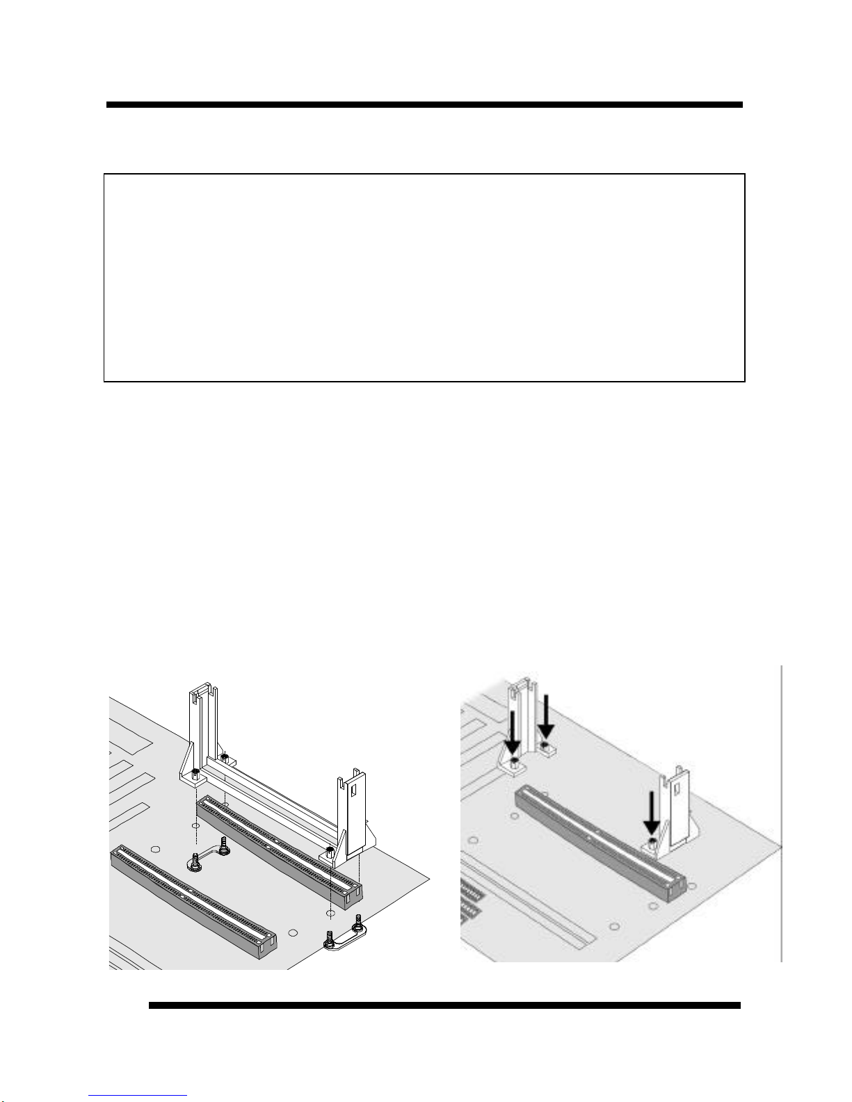
15. DRAM SOCKETS: (4) 168-pin DIMM sockets are provided to support a maximum
RAM memory capacity of 512 MB. DIMM types of 3.3-Volt true SDRAM is supported
and automatically detected by the BIOS.
16. FLOPPY CONNECTOR: Built-in floppy controller supports (2) 5.25" or 3.5"
(1.44MB or 2.88MB) floppy drives.
17. PRIMARY IDE CONNECTOR: Connector for first IDE channel. The on-board PCI
Bus Mastering IDE controller features support for DMA Mode 2 and PIO Modes 3 and
4 for faster data transfer rates. (2) Connectors are provided for support of up to (4) IDE
devices on two channels. ATAPI Tape Drives and CD-ROMs are also supported.
18. SECONDARY IDE CONNECTOR: Connector for second IDE channel.
19. AGP SLOT: AGP (Accelerated Graphics Port) is a new bus interface for high
performance graphics capabilities, especially 3D.

INTRODUCTIONINTRODUCTION
P6B40D-A5 User’s ManualP6B40D-A5 User’s Manual 99
Comprehensive Mainboard View

P6B40D-A5 User’s ManualP6B40D-A5 User’s Manual
1010
INSTALLATION
Static Precautions
Static electricity can be a serious danger to the electronic components on this mainboard. To
avoid damage caused by electrostatic discharge, observe the following precautions:
üDon’t remove the mainboard from its anti-static packaging until you are ready to install
it into a computer case. Also, handle add-in cards and modules by the edges or mounting
bracket.
üBefore you handle the mainboard in any way, touch a grounded, anti-static surface, such
as an unpainted portion of the system chassis, for a few seconds to discharge any built-
up static electricity.
Installing the CPU
Your P6B40D-A5 mainboard features dual “SLOT 1” architecture, a design that can
accommodate dual Intel® Pentium®II processors as well as single Celeron®processor.
Before installing the CPU, attach the retention mechanism first.
Attaching the Retention Mechanism
For Pentium II CPUs: Locate SLOT 1. Attach the Retention Mechanism as illustrated
below. (Fig.1)
For Celeron CPUs: Locate SLOT 1. Push the Retention Mechanisms until they are firmly
locked into place. (Fig.2)
* Make sure all components
are correctly oriented.
Fig. 1 Fig. 2

INSTALLATIONINSTALLATION
P6B40D-A5 User’s ManualP6B40D-A5 User’s Manual 1111
Warning!
üü For a single CPU system: You must insert the CPU into the First Slot 1 socket and the
T510 GTL+ Bus Terminator into the second Slot 1 socket.
üü For a dual CPU system: You must use only Pentium II CPUs for the dual CPU system.
Do not use two Celeron CPUs. It is recommended that you use two identical CPUs in
your system. If you use CPUs with different speed requirements, you must set the CPU
Clock Selection Jumper Block to the lower frequency.
üü CPU cooling fan: It is required to use a CPU Cooling Fan to prevent the CPU from
overheating. Install the fan first before inserting the CPU into the socket.
Installing Pentium®II or Celeron®CPU
1. Slide the CPU down into the retention mechanism. Make sure the CPU is correctly
oriented. (Fig. 1)
2. Seat the CPU firmly into the slot until the two tabs on the CPU click outwards to lock
the CPU in place. (Fig. 2)
Fig. 1
Fig. 2

INSTALLATIONINSTALLATION
P6B40D-A5 User’s ManualP6B40D-A5 User’s Manual
1212
Setting the Jumpers
Jumpers are used on this mainboard to select
various settings and features. A 2-pin jumper
has two settings: Open and Short (or Closed).
The jumper is closed by placing the Jumper
Cap across the two pins, thereby connecting
them. 3-pin jumpers can be set to pins 1-2 or 2-
3 connected. Pin-1 is labeled on the circuit
board.
Setting the CPU Clock Selection Jumper (JP5)
After installing the CPU, you must set the
clock selection jumper to match the frequency
of the CPU. Find the Jumper Block labeled
JP5 on the mainboard. Set the jumper
according to the table at right for the CPU
frequency you are using.
The CPU Clock corresponds to the number
marked on the CPU. The Bus Clock when
multiplied with the Ratio gives the CPU
Clock.
üü For a dual CPU system: It is recommended that you use two identical CPUs in your
system. If your CPUs have different speed requirements, you must set the CPU Clock
Selection Jumper Block to the lower frequency.
•If you are uncertain about the speed requirements of your particular CPU, you should
obtain Technical Documentation from the manufacturer. Such information is available
via the Intel WWW site.
3-pin Jumper 2-pin Jumper
Pin 1-2 Open
Pin 2-3 Short
CPU Clock Ratio Bus Clock
233MHz x3.5 66MHz
266MHz x4.0 66MHz
300MHz x4.5 66MHz
333MHz x5.0 66MHz
366MHz x5.5 66MHz
350MHz x3.5 100MHz
400MHz x4.0 100MHz
450MHz x4.5 100MHz
500MHz x5.0 100MHz
550MHz x5.5 100MHz

INSTALLATIONINSTALLATION
P6B40D-A5 User’s ManualP6B40D-A5 User’s Manual 1313
These jumpers automatically set the ISA Clock as well.
Setting the Bus Clock Override Jumper (JP21)
•Intel 440BX chipset supports only 66/100 MHz bus clock. The 66.8 MHz bus clock can
be extended to 68.5, 75 or 83.3 MHz, and the 100 MHz bus clock to 103, 112 or 133.3
MHz for internal test only (Please refer to Chipset Features Setup on page 29).
•Setting the Bus Clock Override Jumper to Enabled overrides the CPU’s default Bus
Clock and set it at 100 MHz.
•Over-clocking may cause serious system damage.

INSTALLATIONINSTALLATION
P6B40D-A5 User’s ManualP6B40D-A5 User’s Manual
1414
Connections
Cooling Fan (J7, J7A and JP18)
J7, J7A and JP18 are small 3-pin Header
Connectors that provide 12-Volt power for CPU and
chassis cooling fans. Plug in the fan cable to the
connector. Pin-2 corresponds to the RED power
lead as shown:
CPU Thermal Sensor (JP10 and JP10A)
For the CPU Temperature Monitoring function to work properly,
you must use the optional CPU Cooling Fan provided by the
manufacturer. Hook the Thermal Sensor lead attached on the Fan
to this connector, regardless of the polarity.
G
N
D
1
2
V
G
N
D
Fan Power
Thermal
Sensor

INSTALLATIONINSTALLATION
P6B40D-A5 User’s ManualP6B40D-A5 User’s Manual 1515
Soft Power Switch (JP9)
Connects to the Power Switch featured on ATX case designs.
This switch must be hooked up before the system can be powered
on, unlike traditional “Baby-AT” designs where the power switch
is located on the Power Supply itself.
Note: Under the following two conditions, you have to press and
hold the switch for longer than 4 seconds to power off your
system, regardless of the BIOS setting (Refer to page 32).
•Shortly after the system is powered on, when the BIOS
message is not yet appear.
•When CPU hangs.
IDE Activity LED (JP2)
Hook the IDE LED lead to this connector, with the RED
lead corresponding to Pin-1.
Power Supply Connector
This mainboard features an ATX-style Power Supply Connector. This connector is keyed to
prevent connection in the wrong direction. Line up the locking mechanism on the connector
from the Power Supply with the tab on the mainboard connector. Press down until the two
connectors are locked.

INSTALLATIONINSTALLATION
P6B40D-A5 User’s ManualP6B40D-A5 User’s Manual
1616
System Function Connector Block (J11)
Pins [3 & 5] Turbo LED switch - The Turbo function is not supported by this
mainboard. Therefore, the Turbo LED will always remain lit as long as the system power
is on.
Pins [7 & 9] SMI suspend switch lead - If your system’s case has a suspend switch,
hook the lead from the switch to pins 7 & 9. A suspend switch is used to save electricity
by putting the system into a suspend mode when the computer is not being used. This
switch could also be used by the Turbo switch on the front of the system, since this
mainboard does not support that function. For this switch to be functional, it must first be
enabled in the Power Management Setup in the BIOS Setup utility.
Pins [17 & 19] Reset switch lead - Connects to the Reset Switch lead from the system’s
case. The reset switch is used to “cold-boot” the system without actually turning off the
power, reducing wear and tear on the power supply.
Pins [2, 6, 8, 10] Keyboard lock switch lead - Pins 2 & 6 connect to the Power LED
from the system’s case. Pins 8 & 10 connect to the case-mounted keylock switch.
Pins [14 & 20] Speaker connector - Connects to the Speaker lead from the system’s
case.
Serial and Parallel Ports
A 25-pin D-Sub header is provided on the back panel for a
multi-mode bi-directional parallel port.
Two 9-pin D-Sub headers are also provided on the back
panel for Serial ports.
* Modem Ring-In Power On
Install a modem (normally to COM2) and enable Power On
ParallelPort
COM1COM2

INSTALLATIONINSTALLATION
P6B40D-A5 User’s ManualP6B40D-A5 User’s Manual 1717
by Ring/LAN function from BIOS setup. (Please refer to page 32). This allows the modem to
remotely power on the system.
IrDA-Compliant Infrared Module Connector (JP4)
The IrDA connector bracket hooks directly to this connector on the
mainboard. This connector provides support for the optional
wireless transmitting and receiving infrared module. You must
first configure through the BIOS setup where UART2 is directed,
COM2 or IrDA.
* Pin 6 is reserved for consumer IR.
Wake-up On LAN Connector (J12)
The Wake-up On LAN function will allow the network to wake up
a Soft Power Down (Soft-Off) PC. However, if your system is in
the Suspend mode, you can wake-up the system only through an
IRQ or DMA interrupt. To use the Wake-up On LAN function,
you must enable the “Power On by Ring/LAN” field in the Power
Management Setup of the Award BIOS. Connect the cable that
comes with your LAN card to location J12 on the system board.
Refer to the add-in card’s manual for details. Note: Your LAN
card must support Magic Packet in order to use the Wake-up-On-
LAN function.

INSTALLATIONINSTALLATION
P6B40D-A5 User’s ManualP6B40D-A5 User’s Manual
1818
Power State Function (JP19)
This feature will power on the PC when power returns after a power failure. Set JP19 to On
(short) to enable this function.
“PWRON After PWR-Fail” in the Power Management Setup must be set accordingly.
Refer to pages 31 and 32 for more information.
USB Connector
This 8-pin connector permits connection of two USB peripheral
devices directly to the system without an external hub.
PS/2 Keyboard and Mouse Connectors
These two connectors are located on the back panel of the
mainboard.
Floppy drives
The on-board floppy controller supports (2) floppy disk drives with the floppy ribbon cable
provided. Make sure the RED stripe on the ribbon cable is oriented towards Pin-1. Notice
the “twist” between the sets of connectors on the floppy cable. The floppy drive “A”
position is at the END of the cable, whereas floppy drive “B” is hooked to one of the
connectors on the other side of the twist. The cable provides both “Edge” and “Pin”
connectors for both the A and B positions to match the connector on your floppy drives.
US
B
PS/2
Mouse
PS/2
Keyboard

INSTALLATIONINSTALLATION
P6B40D-A5 User’s ManualP6B40D-A5 User’s Manual 1919
IDE Hard Drives and CD-ROMs
The on-board Enhanced IDE controller can support up to (4) IDE hard drives or other
ATAPI devices, such as CD-ROMs. This controller, as with all Enhanced IDE controllers,
consists of both Primary and Secondary ports. Each port has an associated connector and
cable, which can support up to (2) ATAPI devices each.
All IDE devices have jumpers which allow the user to configure the device as either
“Master” or “Slave”. A Master device is one that is ALONE on the IDE cable, whereas a
Slave device is installed as a SECOND device on the same cable. Keep in mind that the
Master device will appear before the Slave device in the CMOS Setup, as well as the
Operating System software. *Refer to the device documentation for jumper settings.
The Secondary IDE port can be used for up to (2) additional ATAPI devices. Normally it’s
recommended that you connect your first hard drive to the Primary port, and the first CD-
ROM to the Secondary.
Make sure to align the RED stripe on the ribbon cable with Pin-1 on the mainboard IDE
connector. On most hard drives and CD-ROMs, the RED stripe should be oriented towards
the power connector of the device.
Chassis Intrusion Detector (JP20)
This lead works with specially designed chassis for monitoring
the chassis to see if it has been opened.

INSTALLATIONINSTALLATION
P6B40D-A5 User’s ManualP6B40D-A5 User’s Manual
2020
Installing the Memory (DIMM)
•The P6B40D-A5 mainboard has four sockets available for 168-pin DIMMs. They must
be 3.3 volt Unbuffered Synchronous DRAMs (SDRAM) or 3.3 volt EDO RAM.
For using SDRAMs:
•If you are using a CPU with a 100MHz system bus, you can use only the
100MHz (-10 ns) or faster SDRAMs.
•If you are using a CPU with a 66MHz system bus, you can use either the 66
MHz or 100MHz SDRAMs, or mix them both.
•DIMM Sizes supported: 8MB, 16MB, 32MB, 64MB, 128MB, and 256MB
•A total of (4) DIMMs can be installed for a maximum RAM capacity of 1 GB.
To insert the DIMMs, the modules must be oriented in the correct way. Notice the notches
of the DIMM. Align these notches as shown in the diagram below. Gently push the DIMM
until the retainers on both sides of the socket lock the module in place. To remove a DIMM,
push the retainers outward to release the module then pull the module out of the socket.
notch notch
DIMM 4
DIMM 3
DIMM 1
DIMM 2
1
1
1
1
1
Installing an AGP Card
This mainboard provides an AGP slot to support a new generation of graphics cards with
high performance graphics capability.
Note: Make sure that the AGP card is firmly seated in the AGP slot. For the card that
complies with the AGP 1.x specifications, a slightly more force may be required to fully
insert the card into the slot. For cards that comply with AGP 2.0 and later specifications, the
installation should be relatively easy.
Table of contents
Other Tekram Technology Motherboard manuals

Tekram Technology
Tekram Technology P6F40-B5 User manual

Tekram Technology
Tekram Technology P5T30-A4 User manual

Tekram Technology
Tekram Technology P6E40-A4 User manual

Tekram Technology
Tekram Technology P5V30-B4 User manual

Tekram Technology
Tekram Technology P5m4m User manual

Tekram Technology
Tekram Technology S381M User manual

Tekram Technology
Tekram Technology P6BXA User manual

Tekram Technology
Tekram Technology P5T30-B4 User manual

Tekram Technology
Tekram Technology P6L40-A4E User manual