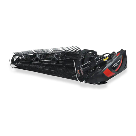
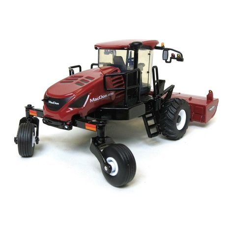
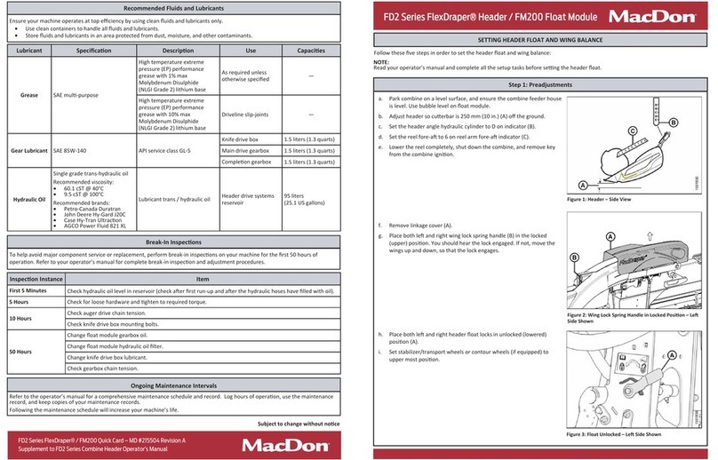
MacDon M2170 User manual

M2170 and M2260
Windrower
Unloading and Assembly Instructions (North America)
262175 Revision A
Original Instruction
The Harvesting Specialists.

M2 Series Windrowers, featuring Dual Direction®and CrossFlex™rear suspension
ϭϬϰϮϱϴϯ
Published August 2023
© 2023 MacDon Industries, Ltd.
The information in this publication is based on the information available and in effect at the time of printing. MacDon
Industries, Ltd. makes no representation or warranty of any kind, whether expressed or implied, with respect to the
information in this publication. MacDon Industries, Ltd. reserves the right to make changes at any time without notice.

Introduction
This manual contains unloading, assembly, and predelivery information for MacDon M2170 and M2260 Windrowers. When
paired with one of the following MacDon auger, draper, or rotary disc headers, this windrower ably cuts and lays a variety
of grain, hay, and specialty crops in windrows:
•A40DX Auger Headers
•D1X or D1XL Draper Headers
•D2 SP Draper Headers
•R2 SP Rotary Disc Headers
•R1 SP Rotary Disc Headers
IMPORTANT:
–A R113 SP Rotary Disc Header is compatible with an M2170 or M2260 Windrower.
–A R116 SP Rotary Disc Header is compatible with an M2170 Windrower, but not an M2260 Windrower.
The windrower features Dual Direction®capability, meaning that it can be driven in cab-forward or engine-forward mode.
The designations right and left are determined by which direction the Operator is facing. The Operator is considered to be
looking cab-forward when they are facing the drive wheels, and engine-forward when facing the engine. This manual uses
the terms right cab-forward, left cab-forward, right engine-forward, and left engine-forward to refer to specific locations on
the machine.
The windrower’s ignition keys should have been bundled with the shipping documents. They are used to start the engine
and to lock the cab doors and tool box compartment.
NOTE:
Keep your MacDon publications up-to-date. The most current version can be downloaded from our website
(www.macdon.com) or from our Dealer-only site (https://portal.macdon.com) (login required).
This document is currently available in English only.
262175 iRevision A


262175 iii Revision A
Introduction ................................................................................................................................................i
Chapter 1: Safety ........................................................................................................................................ 1
1.1 Safety Alert Symbols ...............................................................................................................................1
1.2 Signal Words .........................................................................................................................................2
1.3 General Safety .......................................................................................................................................3
1.4 Hydraulic Safety .....................................................................................................................................5
1.5 Tire Safety.............................................................................................................................................6
1.6 Battery Safety ........................................................................................................................................7
1.7 Welding Precautions ...............................................................................................................................8
1.8 Engine Safety....................................................................................................................................... 12
1.8.1 High-Pressure Rail ........................................................................................................................ 12
1.8.2 Engine Electronics ........................................................................................................................ 13
1.9 Safety Signs ......................................................................................................................................... 14
Chapter 2: Unloading Windrower............................................................................................................ 15
Chapter 3: Assembling Windrower.......................................................................................................... 17
3.1 Lowering Steps..................................................................................................................................... 17
3.2 Retrieving Ignition Keys and Checking Shipped Parts................................................................................... 18
3.3 Installing Caster Wheels......................................................................................................................... 23
3.4 Installing Drive Wheels .......................................................................................................................... 26
3.5 Repositioning Right Leg ......................................................................................................................... 29
3.6 Repositioning Casters and Installing Anti-Shimmy Dampeners ...................................................................... 33
3.7 Installing Windshield Access Step ............................................................................................................ 38
3.8 Positioning Mirror Arms......................................................................................................................... 39
3.9 Installing Slow Moving Vehicle Signs ........................................................................................................ 40
3.10 Replacing Speed Identification Symbol Decal –For Windrowers used in the United States of
America only ....................................................................................................................................... 42
3.11 Installing Rear Ballast Package –For use with Draper Headers Only ............................................................. 43
3.12 Lubricating Windrower ........................................................................................................................ 48
Chapter 4: Performing Predelivery Checks.............................................................................................. 49
4.1 Completing Predelivery Checklist............................................................................................................. 49
4.1.1 Recording Serial Numbers ............................................................................................................. 49
4.1.2 Checking Engine Air Intake............................................................................................................. 50
4.1.3 Checking and Adding Engine Oil...................................................................................................... 51
4.1.4 Checking and Adding Hydraulic Oil .................................................................................................. 52
4.1.5 Checking Fuel Separator................................................................................................................ 54
4.1.6 Checking And Adding Engine Coolant............................................................................................... 54
4.1.7 Checking Engine Gearbox Lubricant Level and Adding Lubricant –M2170 Windrowers............................. 55
4.1.8 Checking Engine Gearbox Lubricant Level and Adding Lubricant –M2260 Windrowers............................. 56
4.1.9 Checking Air Conditioning Compressor Belts ..................................................................................... 57
TABLE OF CONTENTS

262175 iv Revision A
4.1.10 Starting Engine .......................................................................................................................... 58
Troubleshooting Engine Starting Problems ...................................................................................... 62
4.1.11 Checking and Adding Wheel Drive Lubricant –10 Bolt Wheels ........................................................... 63
4.1.12 Checking and Adding Wheel Drive Lubricant –12 Bolt (Optional)........................................................ 63
4.1.13 Checking Tire Pressure ................................................................................................................ 64
4.2 Performing Operational Checks............................................................................................................... 70
4.2.1 Checking Operating Safety System .................................................................................................. 70
4.2.2 Checking HarvestTouch™Display Status Screen and Auto Lights ........................................................... 71
4.2.3 Checking HarvestTouch™Display Gauges .......................................................................................... 73
4.2.4 Setting Language ......................................................................................................................... 74
4.2.5 Setting Units of Measurement........................................................................................................ 76
4.2.6 Setting Time and Date .................................................................................................................. 77
4.2.7 Setting Windrower Tire Size and Wheel Type .................................................................................... 80
4.2.8 Checking Engine Speed ................................................................................................................. 81
4.2.9 Checking Selective Catalytic Regeneration Conditioning Mode ............................................................. 82
4.2.10 Checking Exterior Lights............................................................................................................... 84
4.2.11 Checking Horn ........................................................................................................................... 88
4.2.12 Checking Interior Lights ............................................................................................................... 89
4.2.13 Checking Climate Controls ........................................................................................................... 89
4.2.14 Checking Radio and Activating Bluetooth®Feature ........................................................................... 91
4.3 Checking Manuals................................................................................................................................. 93
4.4 Performing Final Steps........................................................................................................................... 94
Chapter 5: Attaching Headers to Windrower.......................................................................................... 95
5.1 A40DX Auger Header ............................................................................................................................ 95
5.1.1 Attaching Forming Shield to Windrower........................................................................................... 95
5.1.2 Attaching A40DX Auger Header ...................................................................................................... 97
5.1.3 Connecting A40DX Auger Header Hydraulic and Electrical Systems ..................................................... 106
5.1.4 Detaching A40DX Auger Header ................................................................................................... 109
5.1.5 Removing Forming Shield from the Windrower ............................................................................... 116
5.2 D2 SP Series Draper Header ................................................................................................................. 118
5.2.1 Attaching Draper Header Supports................................................................................................ 118
5.2.2 Attaching D2 SP Series Draper Header ........................................................................................... 119
5.2.3 Connecting Header Hydraulic and Electrical Systems ........................................................................ 128
5.2.4 Detaching D2 SP Series Draper Header .......................................................................................... 132
5.3 D1X and D1XL Series Draper Headers ..................................................................................................... 139
5.3.1 Attaching Draper Header Supports................................................................................................ 139
5.3.2 Attaching D1X and D1XL Series Draper Headers............................................................................... 140
5.3.3 Connecting Header Hydraulic and Electrical Systems ........................................................................ 148
5.3.4 Detaching D1X and D1XL Series Draper Headers .............................................................................. 152
5.4 R2 Series Rotary Disc Header ................................................................................................................ 159
5.4.1 Attaching Forming Shield to the Windrower ................................................................................... 159
5.4.2 Attaching R2 Series Rotary Disc Header.......................................................................................... 161
TABLE OF CONTENTS

262175 vRevision A
5.4.3 Connecting R2 Series Rotary Disc Header Hydraulic and Electrical Components –M2170
Windrower ............................................................................................................................... 169
5.4.4 Connecting R2 Series Rotary Disc Header Hydraulic and Electrical Systems –M2260 Windrower.............. 174
Auger/Rotary Disc/Draper-Ready Configuration –Quick Coupler Connections ..................................... 175
Rotary Disc-Only Configuration –Hard-Plumbed Connections........................................................... 180
Rotary Disc-Only Configuration –Quick Coupler Connections ........................................................... 184
5.4.5 Detaching R2 Series Rotary Disc Header ......................................................................................... 188
5.4.6 Removing Forming Shield from the Windrower ............................................................................... 197
5.5 R1 Series Rotary Disc Header ................................................................................................................ 199
5.5.1 Attaching R1 Series Rotary Disc Header.......................................................................................... 199
5.5.2 Connecting R1 Series Rotary Disc Header Hydraulic and Electrical Systems –M2170 Windrower.............. 206
5.5.3 Connecting R113 Rotary Disc Header Hydraulic and Electrical Systems –M2260 Windrower ................... 209
Auger/Rotary Disc/Draper-Ready Configuration –Quick Coupler Connections ..................................... 211
Rotary Disc-Only Configuration –Hard-Plumbed Fittings.................................................................. 213
Rotary Disc-Only Configuration –Quick Coupler Connections ........................................................... 216
5.5.4 Detaching R1 Series Rotary Disc Header ......................................................................................... 219
5.6 Calibrating Header on HarvestTouch™Display.......................................................................................... 227
5.6.1 Calibrating Knife Drive on HarvestTouch™Display –M2 Series Windrowers .......................................... 227
5.6.2 Calibrating Header Position Sensors on HarvestTouch™Display .......................................................... 231
5.7 Adjusting Header Settings on HarvestTouch™Display ................................................................................ 235
Chapter 6: Reference .............................................................................................................................. 239
6.1 Navigating HarvestTouch™Display ......................................................................................................... 239
6.2 Coolant Specifications ......................................................................................................................... 241
6.3 Fuel Specifications .............................................................................................................................. 242
6.4 Torque Specifications .......................................................................................................................... 243
6.4.1 Metric Bolt Specifications ............................................................................................................ 243
6.4.2 Metric Bolt Specifications –Cast Aluminum .................................................................................... 245
6.4.3 O-Ring Boss Hydraulic Fittings –Adjustable .................................................................................... 246
6.4.4 O-Ring Boss Hydraulic Fittings –Non-Adjustable.............................................................................. 247
6.4.5 O-Ring Face Seal Hydraulic Fittings................................................................................................ 248
6.4.6 Tapered Pipe Thread Fittings........................................................................................................ 249
6.5 Conversion Chart................................................................................................................................ 251
6.6 Definitions ........................................................................................................................................ 252
Predelivery Checklist .............................................................................................................................. 255
Lubricants, Fluids, and System Capacities ............................................................................................. 257
TABLE OF CONTENTS


262175 1Revision A
Chapter 1: Safety
Understanding and consistently following these safety procedures will help to ensure the safety of those operating the
machine and of bystanders.
1.1 Safety Alert Symbols
The safety alert symbol indicates important safety messages in this manual and on safety signs on the machine.
1000915
Figure 1.1: Safety Symbol
This symbol means:
•ATTENTION!
•BECOME ALERT!
•YOUR SAFETY IS INVOLVED!
Carefully read and follow the safety message accompanying this
symbol.
Why is safety important to you?
•Accidents disable and kill
•Accidents cost
•Accidents can be avoided

262175 2Revision A
1.2 Signal Words
Three signal words, DANGER,WARNING, and CAUTION, are used to alert you to hazardous situations. Two signal words,
IMPORTANT and NOTE, identify non-safety related information.
Signal words are selected using the following guidelines:
DANGER
Indicates an imminently hazardous situation that, if it is not prevented, will result in death or serious injury.
WARNING
Indicates a potentially hazardous situation that, if it is not prevented, could result in death or serious injury. It may also
be used to alert you to unsafe practices.
CAUTION
Indicates a potentially hazardous situation that, if it is not prevented, may result in minor or moderate injury. It may
also be used to alert you to unsafe practices.
IMPORTANT:
Indicates a situation that, if not prevented, could result in a malfunction or damage to the machine.
NOTE:
Provides additional information or advice.
SAFETY

262175 3Revision A
1.3 General Safety
Operating, servicing, and assembling machinery presents several safety risks. These risks can be reduced or eliminated by
following the relevant safety procedures and wearing the appropriate personal protective equipment.
1000004
Figure 1.2: Safety Equipment
CAUTION
The following general farm safety precautions should be part of
your operating procedure for all types of machinery.
Wear all protective clothing and personal safety devices that
could be necessary for the job at hand. Do NOT take chances.
You may need the following:
•Hard hat
•Protective footwear with slip-resistant soles
•Protective glasses or goggles
•Heavy gloves
•Wet weather gear
•Respirator or filter mask
1000005
Figure 1.3: Safety Equipment
In addition, take the following precautions:
•Be aware that exposure to loud noises can cause hearing
impairment. Wear suitable hearing protection devices such
as earmuffs or earplugs to help protect against loud noises.
1010391
Figure 1.4: Safety Equipment
•Provide a first aid kit in case of emergencies.
•Keep a properly maintained fire extinguisher on the
machine. Familiarize yourself with its use.
•Keep young children away from machinery at all times.
•Be aware that accidents often happen when Operators are
fatigued or in a hurry. Take time to consider the safest way
to accomplish a task. NEVER ignore the signs of fatigue.
SAFETY

262175 4Revision A
1000007
Figure 1.5: Safety around Equipment
•Wear close-fitting clothing and cover long hair. NEVER wear
dangling items such as hoodies, scarves, or bracelets.
•Keep all shields in place. NEVER alter or remove safety
equipment. Ensure that the driveline guards can rotate
independently of their shaft, and that they can telescope
freely.
•Use only service and repair parts made or approved by the
equipment manufacturer. Parts from other manufacturers
may not meet the correct strength, design, or safety
requirements.
1000008
Figure 1.6: Safety around Equipment
•Keep hands, feet, clothing, and hair away from moving
parts. NEVER attempt to clear obstructions or objects from a
machine while the engine is running.
•Do NOT modify the machine. Unauthorized modifications
may impair the functionality and/or safety of the machine. It
may also shorten the machine’s service life.
•To avoid injury or death from the unexpected startup of the
machine, ALWAYS stop the engine and remove the key from
the ignition before leaving the operator’s seat for any
reason.
1000009
Figure 1.7: Safety around Equipment
•Keep the machine service area clean and dry. Wet and/or
oily floors are slippery. Wet spots can be dangerous when
working with electrical equipment. Ensure that all electrical
outlets and tools are properly grounded.
•Keep the work area well-lit.
•Keep machinery clean. Straw and chaff on a hot engine are
fire hazards. Do NOT allow oil or grease to accumulate on
service platforms, ladders, or controls. Clean machines
before they are stored.
•NEVER use gasoline, naphtha, or any volatile material for
cleaning purposes. These materials may be toxic and/or
flammable.
•When storing machinery, cover any sharp or extending
components to prevent injury from accidental contact.
SAFETY

262175 5Revision A
1.4 Hydraulic Safety
Because hydraulic fluid is under extreme pressure, hydraulic fluid leaks can be very dangerous. Follow the proper safety
procedures when inspecting hydraulic fluid leaks and servicing hydraulic equipment.
1001205
Figure 1.8: Testing for Hydraulic Leaks
•Always place all hydraulic controls in NEUTRAL before
leaving the operator’s seat.
•Ensure that all of the components in the hydraulic system
are kept clean and in good condition.
•Replace any worn, cut, abraded, flattened, or crimped hoses
and steel lines.
•Do NOT attempt any makeshift repairs to hydraulic lines,
fittings, or hoses by using tapes, clamps, cements, or
welding. The hydraulic system operates under extremely
high pressure. Makeshift repairs can fail suddenly and create
hazardous conditions.
1001207
Figure 1.9: Hydraulic Pressure Hazard
•Wear proper hand and eye protection when searching for
high-pressure hydraulic fluid leaks. Use a piece of cardboard
as a backstop instead of your hands to isolate and identify
a leak.
•If you are injured by a concentrated, high-pressure stream
of hydraulic fluid, seek medical attention immediately.
Serious infection or a toxic reaction can develop from
hydraulic fluid piercing the skin.
1000013
Figure 1.10: Safety around Equipment
•Ensure that all components are tight and that steel lines,
hoses, and couplings are in good condition before applying
pressure to a hydraulic system.
SAFETY

262175 6Revision A
1.5 Tire Safety
Understand the risks of handling tires before performing maintenance tasks.
1000020
Figure 1.11: Overinflated Tire
WARNING
•A tire can explode during inflation, causing serious injury
or death.
•Follow the proper procedures when mounting a tire. Failure
to do so can produce an explosion, causing serious injury
or death.
1000019
Figure 1.12: Safely Inflating Tire
WARNING
•Do NOT remove, install, or repair a tire on a rim unless you
have the proper equipment and experience to perform the
task. Take the tire and rim to a qualified tire repair shop if
necessary.
•Ensure that the tire is correctly seated on the rim before
inflating it. If the tire is not correctly positioned on the rim
or is overinflated, the tire bead can loosen on one side
causing air to escape at high speed and with great force. An
air leak of this nature can thrust the tire in any direction,
endangering anyone in the area.
•Do NOT stand over the tire when inflating it. Use a clip-on
chuck and extension hose when inflating a tire.
•Do NOT exceed the maximum inflation pressure indicated
on the tire label.
•Never use force on an inflated or partially-inflated tire.
•Ensure that all air is removed from the tire before removing the tire from the rim.
•Never weld a wheel rim.
•Replace tires that have defects. Replace wheel rims that are cracked, worn, or severely rusted.
SAFETY

262175 7Revision A
1.6 Battery Safety
Working with lead-acid vehicle batteries presents several safety risks.
1000015
Figure 1.13: Safety around Batteries
WARNING
•Keep all sparks and flames away from batteries. The
electrolyte fluid in the battery cells emits an explosive gas
which can build up over time.
•Ensure that there is adequate ventilation when charging the
battery.
1000016
Figure 1.14: Safety around Batteries
WARNING
•Wear safety glasses when working near batteries.
•To avoid the loss of electrolyte fluid, do NOT tip a battery
more than 45° off of its base.
•Battery electrolyte causes severe burns. Ensure that it does
not contact your skin, eyes, or clothing.
•Electrolyte splashed into the eyes is extremely damaging. If
you are treating this condition: force the eye open and flush
it with cool, clean water for 5 minutes. Call a doctor
immediately.
•If electrolyte is spilled or splashed on one’s clothing or their
body, neutralize it immediately with a solution of baking
soda and water, then rinse the strained area with
clean water.
1000017
Figure 1.15: Safety around Batteries
WARNING
•To avoid injury from a spark or short circuit, disconnect the
battery ground cable before servicing any part of the
electrical system.
•Do NOT operate the engine with the alternator or battery
disconnected. With the battery cables disconnected and the
engine running, a high voltage can be built up if the cable
terminals touch the machine frame. Anyone touching the
machine frame under these conditions may be electrocuted.
•When working around batteries, remember that all of the
exposed metal parts are live. Never lay a metal object
across the terminals; this will generate a powerful spark and
can electrocute the holder of the tool if they are not
properly grounded.
•Keep batteries out of reach of children.
SAFETY

262175 8Revision A
1.7 Welding Precautions
Understand these critical precautions before attempting to weld anything on the windrower.
IMPORTANT:
If the procedures below are not followed, the windrower’s electronic components may be damaged. Some components
may only be partially damaged, which would result in some electrical components failing in an intermittent way. Such faults
are very difficult to diagnose reliably.
The windrower is equipped with several sensitive electronic components. Therefore, components to be welded should be
removed from the windrower whenever possible rather than welded in place.
When welding needs to be performed on a header, disconnect the header completely from the windrower before
beginning. These same guidelines apply to plasma cutting, or any other high-current electrical operation performed on the
machine.
IMPORTANT:
Ensure that the windrower is parked on a level surface, the ignition is turned off, and the key is removed before
disconnecting anything.
The following items need to be disconnected:
10176211017621
A
Figure 1.16: Negative Terminals
•Negative battery terminals (A) (two connections)
IMPORTANT:
Always disconnect the battery terminals first, and reconnect
them last.
ϭϬϰϮϯϱϯϭϬϰϮϯϱϯ
A
BB
Figure 1.17: Master Controller
•Master controller (A)
Two connectors: P225 and P224
Location: Behind the cab, near the header lift/fan manifold
To disconnect a connector, press center red tab (B), to
release the latch, then lift the latch and pull the connector
away from the master controller.
IMPORTANT:
When reconnecting these connectors, make sure to latch
them in place.
IMPORTANT:
Do NOT power up or operate the windrower until these
connectors are latched into place.
SAFETY

262175 9Revision A
ϭϬϰϮϯϱϰ
B
A
B
Figure 1.18: Firewall Extension Module
•Firewall extension module (A)
Two connectors: P227 and P226
Location: Behind the cab, near the header lift/fan manifold
To disconnect a connector, press center red tab (B), to
release the latch, then lift the latch and pull the connector
away from the module.
IMPORTANT:
When reconnecting these connectors, make sure to latch
them in place.
IMPORTANT:
Do NOT power up or operate the windrower until these
connectors are latched into place.
1019753
A
B
C
C
Figure 1.19: Engine Control Module
•Engine Control Module (ECM)
Two connectors for Cummins: P100 (A) and J1 Cummins
Proprietary ECM Connector (B)
Location: On the engine
To disconnect the connectors, pull the rubber boot off of
the cover, unlock the latch, and undo the main over-center
latch. Remove strain relief bolts (C) so that the connectors
can be pulled away from the ECM.
IMPORTANT:
Be sure to disconnect both connectors. Note the connector
locations for reinstallation.
IMPORTANT:
Be sure to reconnect the connectors in the proper locations.
Do NOT cross connect the connectors.
1017626
A
Figure 1.20: Cab Connectors
•Cab connectors (A)
Two round connectors: C1 and C2
Location: Under the cab
NOTE:
To disconnect circular Deutsch connectors, rotate the outer
collar counterclockwise.
IMPORTANT:
To connect circular Deutsch connectors without bending the
pins, fully align the plug with the receptacle before pressing
the connector in.
SAFETY

262175 10 Revision A
1017627
A
Figure 1.21: Roof Connectors
•Roof connectors (A)
Four connectors: C10, C12, C13, and C14
Location: Under the cab at the base of the left cab post
NOTE:
To disconnect circular Deutsch connectors, rotate the outer
collar counterclockwise.
IMPORTANT:
To connect circular Deutsch connectors without bending the
pins, fully align the plug with the receptacle before pressing
the connector in.
1017628
A
Figure 1.22: Chassis Relay Module
•Chassis relay module (A)
Three connectors: P240, P241, and P242
Location: Outside the left frame rail near the batteries
1017657
A
Figure 1.23: Engine Harness
•Engine harness (A)
Two round connectors: C30 and C31
Location: Inside the left frame rail, at the rear of the
windrower
NOTE:
To disconnect circular Deutsch connectors, rotate the outer
collar counterclockwise.
IMPORTANT:
To connect circular Deutsch connectors without bending the
pins, fully align the plug with the receptacle before pressing
the connector in.
SAFETY

262175 11 Revision A
1017630
A
Figure 1.24: A/C Box Connectors
•Air conditioning (A/C) box connectors (A)
Two connectors: C15 and C16
Location: Rear of the A/C box
NOTE:
To disconnect circular Deutsch connectors, rotate the outer
collar counterclockwise.
IMPORTANT:
To connect circular Deutsch connectors without bending the
pins, fully align the plug with the receptacle before pressing
the connector in.
1017631
A
Figure 1.25: Wheel Motor Connectors
•Wheel motor connectors (A)
Two round connectors: C25 and C26
Location: Under the center of the frame, just behind the
front cross member
NOTE:
To disconnect circular Deutsch connectors, rotate the outer
collar counterclockwise.
IMPORTANT:
To connect circular Deutsch connectors without bending the
pins, fully align the plug with the receptacle before pressing
the connector in.
To align round connectors:
1. Observe the channel cuts and mating channel protrusions on the inner part of the circular walls of the connectors.
2. Face the mating connectors towards each other, and rotate the connectors so that the channels are aligned.
3. Press the connectors together while turning the outer connector clockwise until the collar locks.
SAFETY

262175 12 Revision A
1.8 Engine Safety
Operating, maintaining, and servicing an engine presents several safety risks. These risks can be reduced or eliminated by
following the relevant safety recommendations.
WARNING
Do NOT use aerosol starting aids such as ether when attempting to start the engine. Use of these substances could
result in an explosion.
CAUTION
•When starting up a new, serviced, or repaired engine, always be ready to stop the engine to prevent overspeeding.
Do this by shutting off the air and/or fuel supply to the engine.
•Do NOT bypass or disable automatic shutoff circuits. These circuits help prevent injury and damage to the engine.
For instructions, refer to the technical manual.
•Inspect the engine for potential hazards.
•Before starting the engine, ensure that no one is on, underneath, or close to the engine. Ensure that bystanders are
clear of the area.
•All protective guards and covers must be installed if the engine must be started to perform service procedures.
•Work around rotating parts carefully.
•If a warning tag is attached to the engine start switch or controls, do NOT start the engine or move the controls.
Consult whoever attached the warning tag before starting the engine.
•Start the engine from the operator’s station. Follow the procedure in the Starting Engine section of the operator’s
manual. Following the correct procedure will help prevent major damage to engine components and prevent
personal injury.
•To ensure that the jacket water heater (if equipped) and/or lubricant oil heater (if equipped) are working correctly,
check the water temperature gauge and/or oil temperature gauge during heater operation.
•Engine exhaust contains combustion products, which can be harmful to your health. Always start and operate the
engine in a well-ventilated area. If the engine is started in an enclosed area, vent the exhaust to the outside.
•Engine exhaust gases become very hot during operation and can burn people and common materials. Stay clear of
the rear of machine and avoid exhaust gases when the engine is running.
NOTE:
If the engine will be operated in very cold conditions, then an additional cold-starting aid may be required.
1.8.1 High-Pressure Rail
Fuel is delivered to the engine under high pressure. The risks of working with fuel under pressure must be understood
before the fuel system can be serviced.
WARNING
•Before disconnecting fuel lines or any other components under high pressure between the fuel pump and the high-
pressure common rail fuel system, confirm that the fuel pressure has been relieved.
•Contact with high-pressure fuel may cause fluid penetration and burn hazards. High-pressure fuel spray presents a
potential fire hazard. Failure to follow these instructions may cause injury or death.
SAFETY
Other manuals for M2170
1
This manual suits for next models
1
Table of contents
Other MacDon Farm Equipment manuals

MacDon
MacDon M105 2011 User manual

MacDon
MacDon R85 User manual

MacDon
MacDon D50 User manual

MacDon
MacDon DWA Guide

MacDon
MacDon M100 2009 User manual

MacDon
MacDon M1240 User manual

MacDon
MacDon R113 User manual

MacDon
MacDon M155 User manual

MacDon
MacDon A30-S User manual

MacDon
MacDon FlexDraper FD1 Series User manual

MacDon
MacDon FlexDraper FD1 Series Parts list manual

MacDon
MacDon FD75 User manual

MacDon
MacDon 973 User manual

MacDon
MacDon C Series User manual

MacDon
MacDon D1 Series User manual

MacDon
MacDon R113 User manual

MacDon
MacDon D60 User manual

MacDon
MacDon HC10 Guide

MacDon
MacDon M155 User manual

MacDon
MacDon D1XL Series User manual