H&S HD 7+4 User manual

Manufactured By
H&S MANUFACTURING CO., INC.
P.O. BOX 768 • (715) 387-3414 FAX (715) 384-5463
MARSHFIELD, WISCONSIN 54449
WARNING
HSMFG0416
READ AND UNDERSTAND THIS MANUAL
BEFORE OPERATING THIS EQUIPMENT.
UNSAFE OPERATION OR MAINTENANCE OF
THIS EQUIPMENT CAN RESULT IN SERIOUS
INJURY OR DEATH.
HD 7+4 FRONT UNLOAD
FORAGE BOX
OPERATOR'S MANUAL &
PARTS BOOK

CONTENTS
Warranty & Warranty Registration Card. . . . . . . . . . . . . . . . . . . . . . . . . . . . . . . . . . . . . . . . . . . . . . . . 1-2
Dealer Pre-Delivery & Delivery Checklist. . . . . . . . . . . . . . . . . . . . . . . . . . . . . . . . . . . . . . . . . . . . . . . . 3
Instructions For Ordering Parts. . . . . . . . . . . . . . . . . . . . . . . . . . . . . . . . . . . . . . . . . . . . . . . . . . . . . . . 50
Be Alert Symbol. . . . . . . . . . . . . . . . . . . . . . . . . . . . . . . . . . . . . . . . . . . . . . . . . . . . . . . . . . . . . . . . . . . . . 5
Explanation of Safety Signs. . . . . . . . . . . . . . . . . . . . . . . . . . . . . . . . . . . . . . . . . . . . . . . . . . . . . . . . . . . 6
Danger - Warning Signs. . . . . . . . . . . . . . . . . . . . . . . . . . . . . . . . . . . . . . . . . . . . . . . . . . . . . . . . . . . . . 7-8
Warning - Owner Must Read and Understand. . . . . . . . . . . . . . . . . . . . . . . . . . . . . . . . . . . . . . . . . . . . . . 9
Warning - Emergency Stop. . . . . . . . . . . . . . . . . . . . . . . . . . . . . . . . . . . . . . . . . . . . . . . . . . . . . . . . . . . . 10
Bolt Torque Chart. . . . . . . . . . . . . . . . . . . . . . . . . . . . . . . . . . . . . . . . . . . . . . . . . . . . . . . . . . . . . . . . . . . 11
Set-Up & Assembly. . . . . . . . . . . . . . . . . . . . . . . . . . . . . . . . . . . . . . . . . . . . . . . . . . . . . . . . . . . . . . . . . 12
Transporting. . . . . . . . . . . . . . . . . . . . . . . . . . . . . . . . . . . . . . . . . . . . . . . . . . . . . . . . . . . . . . . . . . . . . . . . . 13
Preparing for Operation. . . . . . . . . . . . . . . . . . . . . . . . . . . . . . . . . . . . . . . . . . . . . . . . . . . . . . . . . . . . .14
Operation. . . . . . . . . . . . . . . . . . . . . . . . . . . . . . . . . . . . . . . . . . . . . . . . . . . . . . . . . . . . . . . . . . . . . . . 15-16
Adjustments. . . . . . . . . . . . . . . . . . . . . . . . . . . . . . . . . . . . . . . . . . . . . . . . . . . . . . . . . . . . . . . . . . . . 17-20
Service. . . . . . . . . . . . . . . . . . . . . . . . . . . . . . . . . . . . . . . . . . . . . . . . . . . . . . . . . . . . . . . . . . . . . . . . . . . . 21
Optional Features & Accessories. . . . . . . . . . . . . . . . . . . . . . . . . . . . . . . . . . . . . . . . . . . . . . . . . . . . . 22
Lubrication Guide. . . . . . . . . . . . . . . . . . . . . . . . . . . . . . . . . . . . . . . . . . . . . . . . . . . . . . . . . . . . . . . . . 23-24
Decal Location & Identification. . . . . . . . . . . . . . . . . . . . . . . . . . . . . . . . . . . . . . . . . . . . . . . . . . . . 25-26
Parts. . . . . . . . . . . . . . . . . . . . . . . . . . . . . . . . . . . . . . . . . . . . . . . . . . . . . . . . . . . . . . . . . . . . . . . . . . . . 27-49
Parts Notes. . . . . . . . . . . . . . . . . . . . . . . . . . . . . . . . . . . . . . . . . . . . . . . . . . . . . . . . . . . . . . . . . . . . . . 51-52


DEALER PRE-DELIVERY CHECK LIST
After the Forage Box has been completely set-up, check to be certain it is in correct running order before
delivering to the customer. The following is a list of points to inspect. Check off each item as you have made
the proper adjustments and found the item operating satisfactorily.
oForage Box was not damaged in shipment. Check for dents and loose or missing parts. Report damage
immediately to H&S Manufacturing Co., Inc.
oForage Box has been correctly assembled according to the instructions in this manual.
oAll shields and guards are in place and fastened.
oPTO shields turn freely.
oAll grease fittings have been lubricated and gear boxes filled to proper level – See lubrication guide in
this manual.
oAll mechanisms are operating trouble free.
oAll roller chains are at proper tension.
oApron chains are adjusted properly.
oAll bolts and fasteners are tight.
o2extra shear bolts are provided.
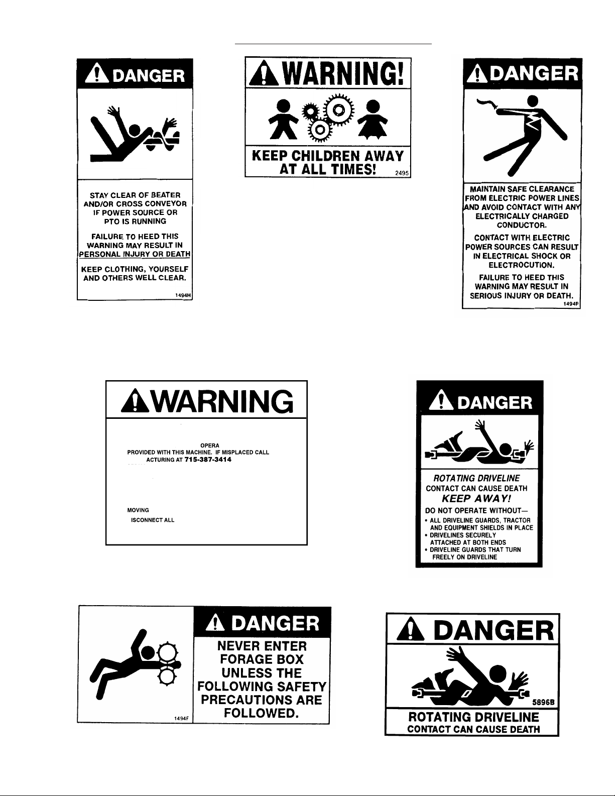
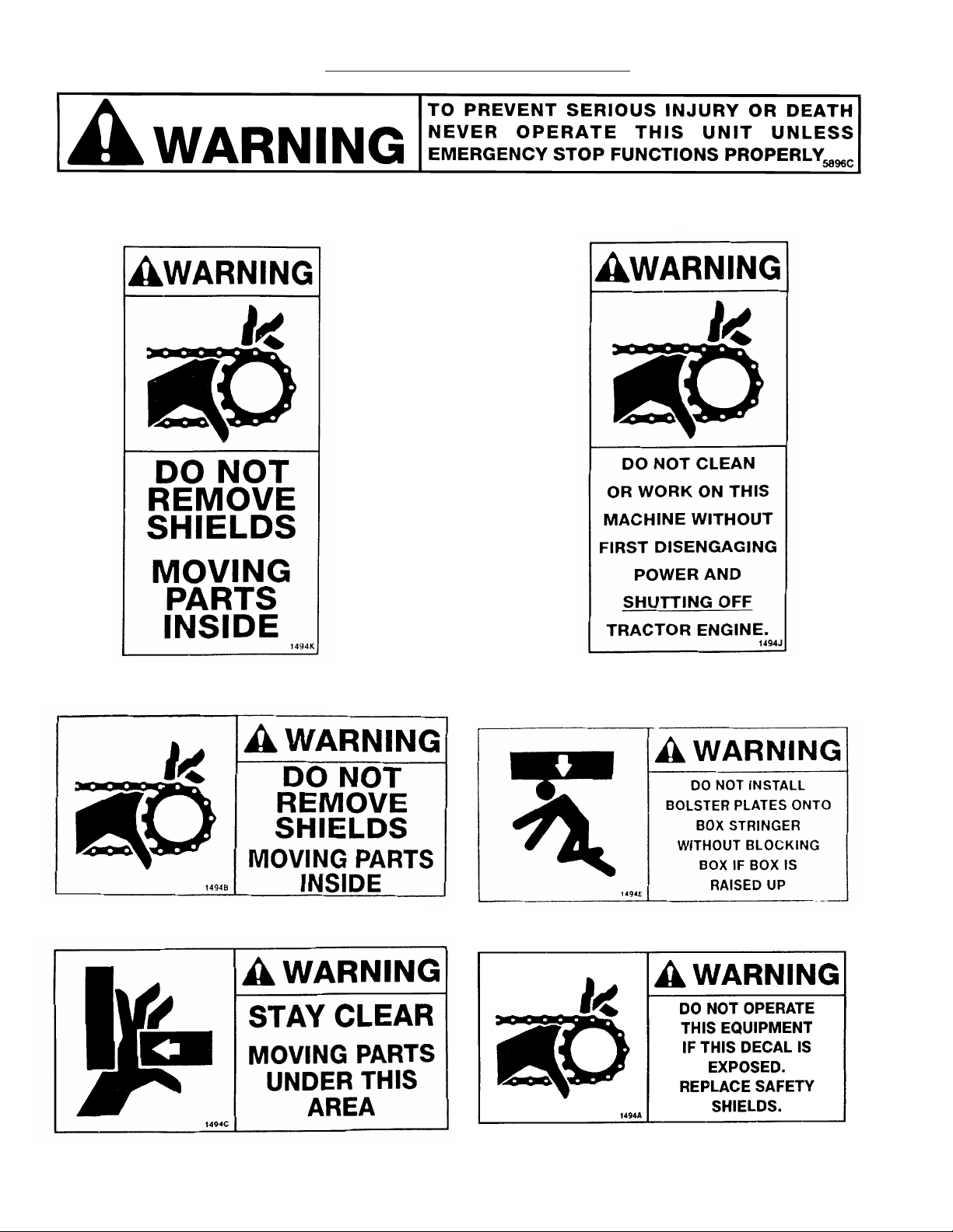
oAll decals are in place and legible.
(Remove Dealers File Copy At Perforation)
(Dealer’s Name)
Model Number
(Signature of Pre-Delivery Inspector) (Inspection Date)
Serial Number
DEALER DELIVERY CHECK LIST
This check list that follows is an important reminder of valuable information that should be passed on to the
customer at the time this Self-Unloading Forage Box is delivered. Check off each item as you explain it to
the customer. This pre-delivery check list, when properly filled out and signed assures the customer that
the pre-delivery service was satisfactorily performed.
oExplain to the customer that the pre-delivery inspection was made.
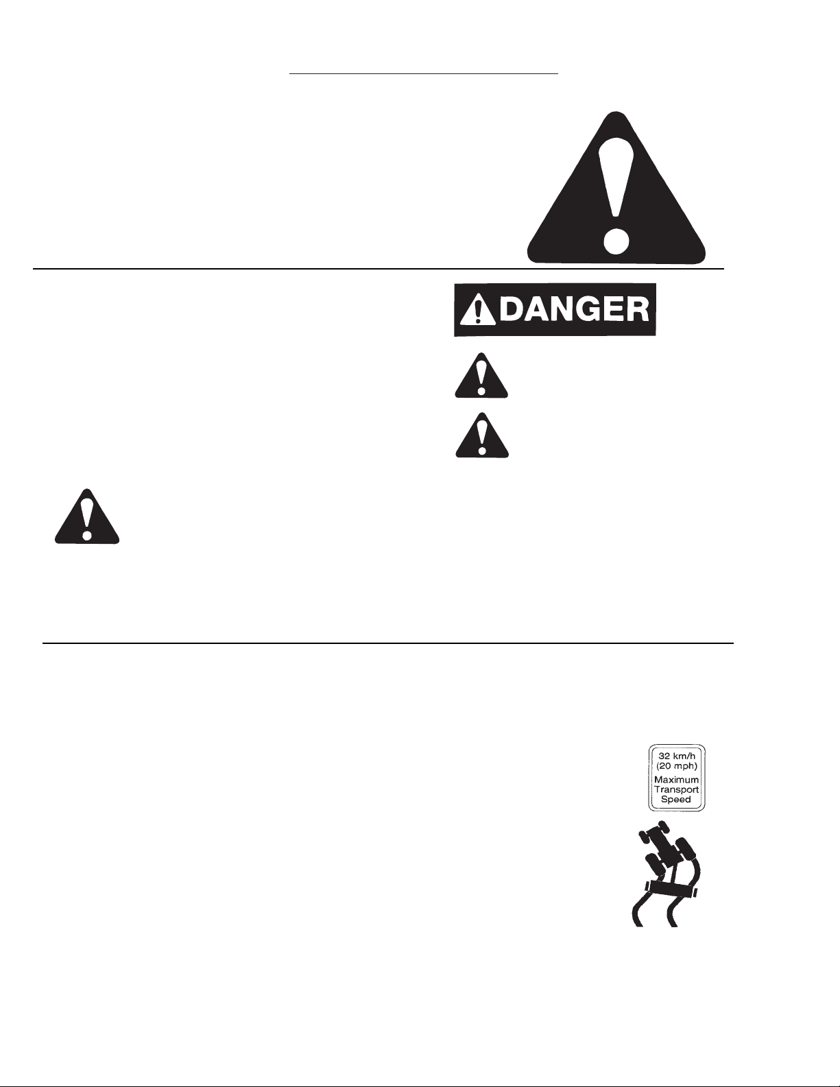
oExplain to the customer all the safety precautions they must exercise when operating this unit.
oExplain recommended loads for different types of materials.
oExplain to customer that regular lubrication is required for proper operation and long life of
machine. Show customer the lubrication section of Owner’s Manual.
o
Give the customer Owner’s Manual and make sure he reads and understands all operating and
service instructions.
oRecord Serial Number in this Manual.
oHave customer sign a completed “Warranty Registration,’’ and mail it promptly.
Dealer’s Name ______________________________ By
___________________________________
Signature of Original Buyer ______________________________________ Date _________________
-3-
Note: Warranty is not valid until warranty card is completed and returned to H&S Mfg. Co., Inc.

INTENTIONALLY LEFT BLANK
-4-

THIS SYMBOL IS USED THROUGHOUT THIS BOOK WHENEVER YOUR PERSONAL SAFETY IS
INVOLVED. TAKE TIME TO BE CAREFUL. REMEMBER: THE CAREFUL OPERATOR IS THE BEST
OPERATOR. MOST ACCIDENTS ARE CAUSED BY HUMAN ERROR. CERTAIN PRECAUTIONS
MUST BE OBSERVED TO PREVENT THE POSSIBILITY OF INJURY OR DAMAGE.
H&S MANUFACTURING CO. INC.
BE
ALERT! YOUR SAFETY
IS INVOLVED.
-5-
SAFETY INFORMATION

-6-
This is the safety-alert symbol. When you see this
symbol on your machine or in this manual, be alert to
the potential for personal injury.
Follow recommended precautions and safe
operating practices.
UNDERSTAND SIGNAL WORDS
A signal word - DANGER, WARNING, or CAUTION is
used with the safety alert symbol. DANGER identifies
the most serious hazards.
Safety signs with signal word DANGER or
WARNING are typically near specific hazards.
General precautions are listed on CAUTION safety
signs.
CAUTION
WARNING
CAUTION
SAFETY INFORMATION
OBSERVE MAXIMUM TRANSPORT SPEED
The maximum transport speed for this implement is 32 km/h (20 m.p.h.).
Some tractors are capable of operating at speeds that exceed the maximum
transport speed of this implement. Regardless of the maximum speed capability
of the tractor being used to tow this implement, do not exceed the implement’s
maximum transport speed.
Exceeding the implements maximum transport speed can result in:
* Loss of control of the tractor/implement combinatio
* Reduced or no ability to stop during brakin
* Implement tire failur
* Damage to the implement structure or its component
Use additional caution and reduce speed when towing under adverse surface
conditions, when turning, and when on inclines.
Do not attempt transport if the fully loaded implement weighs more than 1.5 times
the weight of the tractor.
Keep signs in good condition. Immediately replace any missing or damaged signs.
RECOGNIZE SAFETY INFORMATION
FOLLOW SAFETY INSTRUCTIONS
Carefully read all safety messages in this
manual, and all safety signs on your
machine. Follow all recommended
precautions and safe operating procedures.

-7-
SAFETY INFORMATION
HELP AAAVOID INJURY
TTORS MANUAL H & S
WITH MODEL AND
•READ & UNDERSTTTAND THE
MANUFF
SERIAL NUMBER.
•UNDERSTTTAND ALL SAFETY WWWARNINGS AND FUNCTION OF
CONTROLS.
•KEEP SAFETY DEVICES IN PLACE AND WORKING.
•KEEP YOURSELF AND OTHERS WELL CLEAR OF
PPPARTS.
•D POWER BEFORE SERVICING OR
CLEANING THIS MACHINE.
72203A
•O NOT EXCEED 20 MPH

SAFETY INFORMATION
-8-

W A R N I N G
TO PREVENT SERIOUS INJURY OR DEATH
BEFORE YOU ATTEMPT TO OPERATE THIS EQUIPMENT, READ AND STUDY THE FOLLOWING
INFORMATION. IN ADDITION, MAKE SURE THAT EVERY INDIVIDUAL WHO OPERATES OR WORKS WITH
THIS EQUIPMENT, WHETHER FAMILY MEMBER OR EMPLOYEE, IS FAMILIAR WITH THESE SAFETY
PRECAUTIONS. KNOW HOW TO STOP UNLOADING MECHANISM BEFORE STARTING IT.
EMERGENCY STOP DOES NOT STOP FORAGE BOX WHEN BEING OPERATED AS A REAR
UNLOAD.
If the machine becomes clogged, disengage the PTO or tractor hydraulics. Stop the tractor engine and allow all
mechanisms to stop before cleaning or working on the machine.
DO NOT attempt to perform maintenance or repair with tractor running and PTO or tractor hydraulics hooked
up.
DO NOT step up on machine at any time.
NEVER manually feed material into the beaters.
DO NOT allow minors to operate or be near the machine.
DO NOT ALLOW PERSONNEL OTHER THAN THE QUALIFIED OPERATOR NEAR THE MACHINE.
BEFORE starting tractor, be sure PTO shields turn freely and PTO is securely locked to tractor.
DO NOT clean, adjust, or lubricate the machine when any part is in operation.
CHECK frequently to be assured that the emergency stop mechanism is in proper operating condition. KEEP
hands, feet, and clothing away from beaters when they are revolving .
LOOSE or floppy clothing should not be worn by the operator.
BE SURE the machine is clear of people, tools, and other objects before engaging PTO or tractor hydraulics.
STAY CLEAR of hydraulic lines and fittings. They may be under extreme pressure or heat.
DO NOT step over power take off shaft. Stay clear of PTO at all times.
NEVER start forage box until all guards and safety shields are secured in place.
NEVER put hand in cross conveyor outlet openings while tractor is running.
CAUTION – Beware of low electrical wires.
NEVER hook up 1000 RPM tractor to the forage box.
STAY CLEAR of rear of forage box at all times.
H&S Mfg. Co. always takes the operator and his safety into consideration and guards exposed moving parts for
his protection. However, some areas cannot be guarded or shielded in order to assure proper operation. In
addition, the operators manual and decals on the machine itself warn you of further danger and should be read and
observed closely.
Study The Above Safety Rules
ATTENTION - BE ALERT - YOUR SAFETY IS INVOLVED
-9-
TRACTOR:
This Operators Manual uses the term "Tractor" when identifying the power source.

-10-
A
B
TO PREVENT SERIOUS INJURY OF DEATH NEVER OPERATE THIS UNIT
UNLESS EMERGENCY STOP FUNCTIONS PROPERLY
EMERGENCY STOP
WARNING
SAFETY INFORMATION
1. In case of an emergency, pushing either the stop panel rearward (A), or pulling the trip
cables (B) will stop cross conveyor, beaters, and main apron.
2. Activating emergency stop only stops box functions. The PTO shaft will continue to rotate.
3. Keep excessive slack out of trip cables.
4. Trip emergency stop occasionally, and when starting the unit after periods of storage to insure
proper function.
5. To reset, move lever (C) clock wise to engage position.
C

-11-

SET-UP & ASSEMBLY
-12-
WARNING: Some photographs used in the following pages show guards or
shields removed for clarification. Never operate machine until these guards
or shields are in proper operating position.
NOTE: Determine right or left side of the forage box by viewing it from the rear. If instructions or parts
lists call for hardened bolts, refer to the Cap Screw Torque Value page to identify.
1. Check the Forage Box for proper assembly and adjustment. Make sure that all bolts are
tightened.
2. Properly lubricate the Forage Box before operating. Refer to Lubrication Section of this Operator’s
Manual for locations.
3. GEARBOXES:
Main Apron Drive Gearbox; Keep the main apron gearbox filled to the oil level plug in cover of
gearbox using 85W140 lubricant.
Beater Drive Gearbox; Keep the beater drive gearbox filled to the center of the shafts. Use 80W90
lubricant.
4. Check all lights to make sure that they are functioning properly.

TRANSPORTING
-13-
TRANSPORT LIGHTING & REFLECTORS
WHEN TRANSPORTING ON THE HIGHWAY OR ROADS, PLACE SMV SIGN IN SOCKET PROVIDED
AND REGULARLY CLEAN THE REFLECTIVE TAPE AT THE REAR OF THE FORAGE BOX.
NOTE: Obey all state and local laws, concerning towed equipment, on public roads.
TOWING ON HIGHWAY
To view beyond the back of the Forage Box when transporting the unit on a public highway, consider
obtaining and installing a rear view mirror on your tractor with a wide load mounting bracket.
Transport lighting is standard on
allmodels. The lighting system is
to be connected to the 7 pin
powerreceptacle (per SAEJ560B)
on your tractor. If your tractor
is not equipped with theproper
receptacle, see your tractor
dealer for details. Red reflective
safety decals are on the rear of the
box for safety.
0RXQWLQJ6RFNHWIRU609(PEOHP$
5HG5HIOHFWLYH7DSH%
Mounting Socket for SMV Emblem (A)
Red Reflective Tape (B)
A
B

PREPARING FOR OPERATION
Check over entire unit carefully before first operation. Tighten bolts, set screws, and chains which
may have come loose in handing. Lubricate as explained in the Lubrication Guide. Successful operation will
be achieved by periodic adjustments and experience of the operator. Make sure to read and
understand all adjustments.
TRACTION CONNECTIONS
PTO Drive
-14-
Attach the Forage Box PTO to the tractor PTO shaft locking it into position. Maintain correct distance
between the tractor drawbar hitch, tractor PTO and the universal joint at front of unit. This is necessary
to prevent overextending the universal joint shaft.
IMPORANT! DO NOT operate unless 2” minimum extension is maintained.
After the correct distance is obtained, depress the locking collar against the spring tension, and slide the
yoke onto the tractor PTO shaft. Release the locking collar and move the yoke ahead or back until the
lock engages into the groove on the shaft.
NOTE: Do NOT attempt to use a hammer to help in attaching the PTO drive connection.
The tractor drawbar should be adjusted in relation to the tractor PTO shaft as follows:
1. Hitch point of drawbar 14 inches behind tractor PTO shaft.
2. Hitch point of drawbar at least 8 inches, but not more than 14 inches below PTO shaft.
3. Hitch point of drawbar at least 13 inches, but not more than 22 inches above ground level.
4. When unloading, keep the hitch point of the drawbar and PTO shaft in a straight line to the Forage Box.
If the PTO is at an angle, it will result in a pounding noise and damage to U joints and the safety clutch.
The Power Take Off Shaft from tractor to box should not
be connected for road travel or field operation. Damage
may result to the PTO Shaft. A convenient hanger
is provided to hold PTO shaft during the time it is not being
used to unload.
The telescoping PTO drive is designed to rotate freely inside the drive shield tubes. Run the unloading
mechanism for several minutes. This will serve as a break-in and as a check that all parts are
assembled and lubricated properly.
After you have run the Forage Box for several minutes, check the main apron chains again for proper
adjustment, as paint may initially come off the apron chains and chains may loosen. The main apron
chains must be taken up evenly before you use the forage box. Check again after the first few loads. The
main aprons should be at proper tension at all times. See Adjustment Section for details.
1. Maintain a straight alignment between the Forage Box and the tractor.
2. Maintain a distance of 6”- 12” between the top of the tractor drawbar and the center of the tractor PTO.
An 8” distance is standard.
(Shields are
removed
for viewing)

OPERATION
Check entire Forage Box carefully before first operation. Tighten bolts and set screws that might have
come loose in transporting. Lubricate if needed as explained in the Lubrication Chapter in this manual.
EMERGENCY SHUTDOWN
In case of an emergency, pushing the emergency stop
panel, emergency stop bar, or pulling the safety cable will
stop cross conveyor, beaters, and main aprons. PTO will
continue to rotate. If the Forage Box is plugged with material
or a foreign object becomes lodged in the discharge area,
disengage the PTO. Stop the tractor engine, remove ignition
key, and allow all mechanisms to stop before cleaning or
working on the machine. Trip emergency stop occasionally
to insure proper function.
GENERAL INFORMATION
-15-
CONTROLS & SAFETY EQUIPMENT
Forage Boxes are provided with several features for operator safety and convenience.
Guards & Shields
Whenever possible and without affecting the operation of the Forage Box guards, shields and/or hinged
shields have been used on this equipment to protect potentially hazardous areas. In many places,
decals are also provided to warn of potential dangers as well as to display special operational procedures.
A spring loaded plastic guard which
protects the operator from accidentally being
exposed to the beater and apron at the
discharge opening during operation of the
Forage Box. Keep this guard in proper
position at all times when operating the
forage box.
PTO Shields
Care must be taken to keep male and female driving elements well lubricated and free sliding. The shield
surface must be kept dry, as dirt accumulation on them will quickly cause these units to bind and not
rotate. If, at any time the shields do not turn freely, they should be checked to determine the cause, and
repaired or cleared. DO NOT STEP OVER PTO SHAFT. STAY CLEAR OF ROTATING PTO AT ALL
TIMES. DO NOT OVEREXTEND PTO.
Emergency Stop Panel
Emergency Stop Cable

-16-
OPERATION
OPERATION OF FRONT UNLOAD FORAGE BOX
1. Park the Forage Box on level ground whenever possible during unloading. Lock tractor parking brake
2. Connect the PTO to a tractor with a 540 PTO ONLY, locking securely in place as stated in the
PREPARING FOR OPERATION SECTION.
3. Engage PTO
4. To engage cross conveyor
INTERMITTENTLY, rotate clutch
lever (A) clockwise and hold with hand
pressure. If hand pressure is
removed, the cross conveyor will
stop.
5. To engage the cross conveyor
CONTINUOUSLY, rotate clutch lever
clockwise until it locks in the engage
position. Cross conveyor speed is
controlled by the tractor RPM only.
6. Quickly engaging/disengage beater lever will allow beaters to clear material a little at a time to avoid
exceeding blower capacity. This single lever controls both beater engage/disengage and the speed of
the main feeder aprons. CAUTION: DO NOT ENGAGE BEATERS OR MAIN APRONS WHEN CROSS
CONVEYOR IS FULL OF MATERIAL OR DAMAGE TO FORAGE BOX WILL RESULT.
7. When beaters are clear of material, move control lever to apron speed position. Variable speed
drive offers you a number of unloading speeds to choose from. Rotating the lever downward
starts and gradually increases main apron speed. With experience and depending on the type of forage,
you will be able to select a speed which will match your blower capacity. Unloading speed may also
be varied by increasing or decreasing engine speed of tractor.
8. If it is necessary to trip the stop mechanism and disengage the Forage Box drive before the box
empty, restart unloading by engaging clutch lever.
9. Clean out position is for cleaning out the forage box at the end of the load.
10. When the Forage Box is empty, move the control lever to disengage position. AFTER
UNLOADING, ALWAYS RETURN THE CONTROL LEVER TO THE NEUTRAL POSITION WITH PTO
RUNNING.
11. Disconnect the PTO and place it in the convenient holder for field and road use.
NOTE: Do NOT exceed the rated 540
RPM operating speed of the Forage
Box
A B

-17-
ADJUSTMENTS
MAIN APRON
Main feeder apron adjustment bolts are located behind the convenient access door located in the
bottom portion of rear tailgate .Remove handle nuts (A) to open access door and swing door
downward.
All apron chains must be taken up evenly before you use the forage box . Check again after the first
few loads .The Main Feeder Aprons should be at proper tension at all times .Tighten the full threaded
bolts (B) to adjust aprons .Aprons are properly adjusted when two Cross Slats, or about three feet of
chain lift off the Chain Return Slides from the rear of the box .Maintain this tension when operating the
box.
B
A

A
C
CROSS CONVEYOR
Proper tension should be maintained on cross con-
veyor chain when operating box . To adjust cross
conveyor, loosen the jam nuts (A) on tightener
bolts (B) . Move adjusting nuts (C) on tightener
bolts until proper tension on chain is reached .The
chain is properly adjusted when the center slats
clear the bottom return pan by about 1/16 of an
inch .Adjust both sides equally .Lock in place with
jam nuts.
SHEAR BOLT
The cross conveyor is protected by two shear
bolts, located in the drive sprocket and shear hub
assembly, located at the right hand end of cross
conveyor. Two spare shear bolts are provided.
Always determine the cause of failure and elimi -
nate the cause before installing new shear bolts.
Use only H&S shear bolts when replacing.
-18-
B
ADJUSTMENTS
A .Spare Shear Bolts
B .Shear Bolts
Table of contents
Other H&S Farm Equipment manuals

H&S
H&S Top Shot 5215 User manual

H&S
H&S WIDE BODY Installation and maintenance instructions

H&S
H&S 3108 User manual

H&S
H&S 2217 User manual

H&S
H&S 4142 User manual

H&S
H&S 2208 User manual

H&S
H&S HDII RAKE Installation and maintenance instructions

H&S
H&S 1126 User manual

H&S
H&S HT8 User manual

H&S
H&S 5242 User manual