WRT
WRTB
WRTBSETUP
WSCMD
WSCMD?
WRT
7,
z2
z,;Data
-
writes to VME memory space. (3
-
541
WRTB Data
-
writes to VMEbus memory space. (3
-
56)
WRTBSETUP
z,
7,
z3
-
sets up parameters for a write to VMEbus
memory space. (3
-
57)
WSCMD LA, CMD
-
sends the specified WSP conirnand to a VXI
device. (3
-
581
WSCMD? LA, CMD
-
sends the WSP command to a VXI tlevlce. The
response value is returned in ASCII decimal format. (3
-
59)
The input trigger llnes are any one of the 8
TRIGGER COMMANDS VXlbus TTL trigger lines, either
of
the
2
VXlbus
ECL trlgger lines, the front panel External trlgger
input, the VX4521's software trigger, or the IEEE-488 GET signal The output trigger
lines may be any combination of the 8 TTL trlgger lines, the 2 ECL trrgger lrrles or th~
front panel output trlgger line. All coninlands must terrnlnate with a
<
CH
>
.c
LF
>
ConnTrg (Source Dest IEnblll
-
allows
connecting
one Input trlgger Ilne to orit: or riiore
output trigger I~nes.(3
-
63)
DcorrTrg (Source IDestl)
-
selectively
d~sconriectsan Input trlgger Ilne from o1ie or
more outp~lttrigger Ilnes, without aflectcng any other output trigger llrle
coririectlorls to that input Ilne.
(3
-
64)
EriblTrg (IDestl] enables the trlgger llne connectlon estabhshed wlth thv Cor~nTrg
conirnand (3
-
65)
nsblTrcJ(IOestl) dlsahles the trlgger connectlon set by the ConnTry c~~r~rrlrarid
13 661
DelayTrg (Source Dest Delay IContl [HI [ENBLII
-
speclfles a delay between tlre Inpttt
trlgger event and the output trigger signal.
(3
-
671
PulseTrg (Source Dest Period ICont]
(HI
IENBLI)
-
converts the Input trlgyer event to a
low golng output pulse or square wave of user-definedfrequency.
(3
-
69)
Swlrg generates the VX4521's software trlgger. (3
-
70)
TryCnfg
-
returns the current trigger connectlon matrix In table format. (3
-
71)
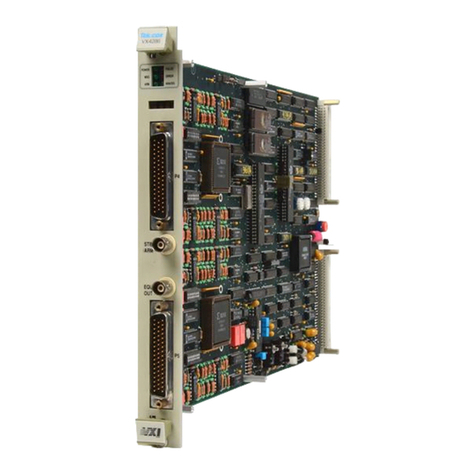
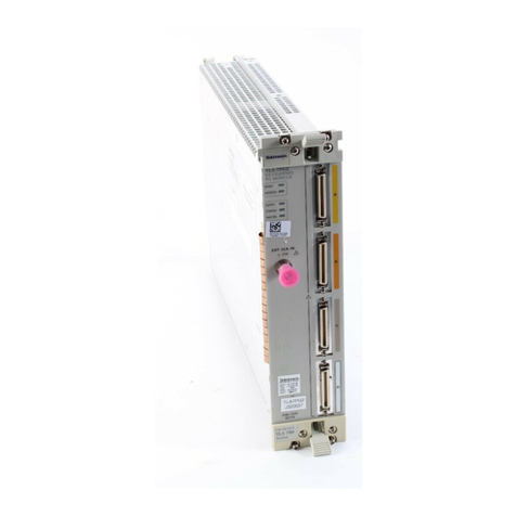
VX4521
INTERFACE MODULE
QUICK
REFERENCE GUIDE
Nurnbers inparentheses refer to the page(s) in the Operating Manual
Be sure all switches are correctly set. (p.
1
-
31
SETUP Follow Installotion guidelines.
Ip.
2
-
1)
LEDs
Power
Faled
MSG
AST
LTN
TLK
SRQ
ATN
REN
When 111, the LEDs irid~catethe following:
power supphes functioning
niodule failure
rnodule is processing a VMEbus cycle
lnd~catesVMEbus activ~tybymonitor~ngAddress Strobe (AS
'
I
a device
IS
addressed as a llstener on the IEEE-488bus
a device 1s addressed as a talker on the IEEE-488 bus
tlw SRQ lilie onttie IEEE 488 bus
IS
set true
the ATN line on the IEEE-488 bus is set true
ttie REN hne on the IEEE-488bus 1s set true
The twodlsplays onthe front panel show IEEE-488
FRONT PANEL DISPLAY bus data In
hexadecimal
format whenever the front
pmel Normallstep sw~tch
IS
In the STEP (up)
pos~f~ori
7Iit3 dlqpldys are turned off whenever the Normallstep swltch Is
In
the
NORMAL
(down)
pos~t~ori
The upper d~splaycorresponds to brts 4 7 on the IEEE 488
d,rtd bus, and the lower drsplay to blts
0
3 of the bus
When the VX4521 is addressed as a
VXI USEf? IFEBACECOMMANDS Listener on the IEEE-488bus, it will
recogn~recertain ASCII strings that
WIII causc an actlor1 to occur or cause a response to be formatted and returned to the
IEEE-488 controller the next time the VX4521 is addressed as a Talker on the bus.
The syntax and symbols used inthe command descriptions are:
(
I
optlorial parameter
( )
grot~pof parameters
<CR>
carriage return (decimal 13. Its use is host-specific and it may not be
required as a terminator. Consult the host's Operating Manual.
