7S11
SECTION 1
7S11 SPECIFICATION
Change information, if any, affecting this section will be found at the rear of the manual.
General Information
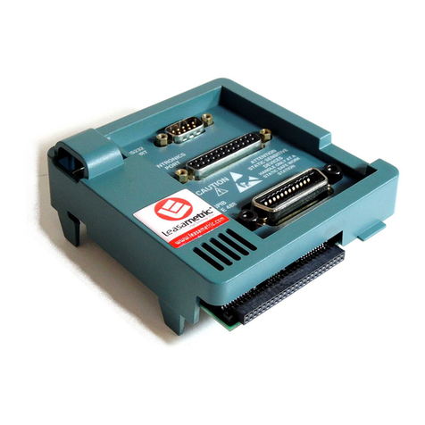
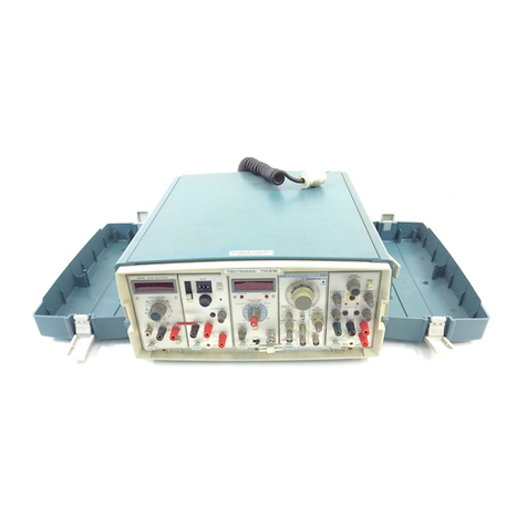
The 7S11 Sampling Unit is asingle channel vertical
amplifier plug-in unit designed for operation in Tektronix
7000-Series Oscilloscopes. The 7S11 accepts the S- Series
Sampling Heads. The Sampling Head determines the input
characteristics and the availability of atrigger pickoff.
The S-Series Sampling Head used can be plugged into the
7S1 1or used remotely on an optional extender cable unit.
The 7S11 provides the power for the sampling head.
Interconnections to the sampling head circuits are provided
by the connector in the sampling head compartment of the
7S11.
The 7S11 and a7T11 Sampling Sweep Unit operated in
the center plug-in compartments of a7000-Series
oscilloscope provide a single channel sampling system. Two
7S11's and one 7T11 provide dual-trace sampling, using the
electronic switching in the oscilloscope vertical amplifier.
X-Y operation is provided by two 7S11's operated in the
center plug-in compartments of the oscilloscope.
If atrigger pickoff is provided in the sampling head,
interconnections between two 7S11's and the 7T11
through the fixed and movable shoes provide atrigger
selection circuit to trigger the 7T11. An internally
reconstructed signal is provided to trigger areal-time
time-base such as the 7B50.
Sampled signals are presented to both the oscilloscope
vertical amplifier and to the front panel connectors for
external use with auxiliary equipment such as pen
recorders.
TABLE 1-1
ELECTRICAL
Characteristic Performance
Deflection Factor
Units/Division
Range
2to 200 in seven steps in 1, 2, 5
sequence. The Units/Division are
those labeled on the sampling head.
TABLE 1-1 (cont)
Characteristic Performance
Gain Accuracy
(Ratio to add
to accuracies of
source, oscillo-
scope, attenu-
ators, etc.)
Within 3% when NORMAL/
SMOOTH function is NORMAL,
with GAIN adjusted at any Units/
Division switch setting. Within 6%
when NORMAL/SMOOTH func-
tion is SMOOTH.
Units/Division
Variable Range Extends deflection factor from 1
unit/division or less to at least 400
units/division.
GAIN Range Permits adjustment of deflection
factor at any Units/Division switch
setting for all, 7000-series oscillo-
scopes.
DELAY Range At least 10 ns.
Memory Slash 0.1 division or less at 20 Hz for
ambient temperature of 0°C to less
than 30°C.
DC OFFSET
Range
-t1 volt to —1 volt or more.'
OFFSET OUT
Range -flO volts to —10 volts or more.
Relation to
actual Offset
Actual Offset =(0.1) (Offset Out)
within 2%.
Source resistance
(related to
actual Offset)
10 kn within 1%.
VERTical SIGnal
OUT
..,, , 200
(Signal input in volts) (. ,.j
Units/Div
within 2%. 2.4 volts peak-to-peak
maximum.
Amplitude in
volts
(Referenced
to input)
Deflection factor
(Referenced
to CRT)
200 mV/displayed division within
3% in +UP or INVERT.
Source resistance 10 kfii within 0.5%.
'unless otherwise stated on sampling head front-panel.
1-1
