Tektronix 7D12 Operating instructions
Other Tektronix Media Converter manuals

Tektronix
Tektronix P6701 User manual
Tektronix
Tektronix P6701A User manual

Tektronix
Tektronix P6701B User manual
Tektronix
Tektronix P6701B User manual
Tektronix
Tektronix WVR52003G User manual
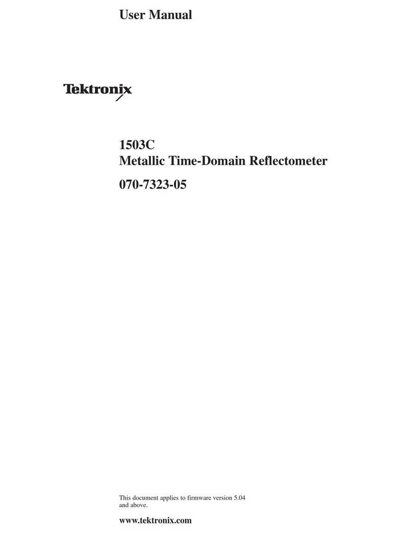
Tektronix
Tektronix 1503C User manual
Tektronix
Tektronix SD-44 User manual
Tektronix
Tektronix MTD200 User manual
Tektronix
Tektronix 7D12 User manual
Tektronix
Tektronix 7D12 Assembly instructions
Tektronix
Tektronix P6701B User manual

Tektronix
Tektronix SD-48 User manual
Tektronix
Tektronix PSC1125 User manual

Tektronix
Tektronix WVR8200 Use and care manual
Tektronix
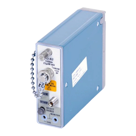
Tektronix SD-42 User manual

Tektronix
Tektronix SD-51 User manual
Tektronix
Tektronix TDC5 User manual
Tektronix
Tektronix SA-42 User manual
Popular Media Converter manuals by other brands

H&B
H&B TX-100 Installation and instruction manual

Bolin Technology
Bolin Technology D Series user manual

IFM Electronic
IFM Electronic Efector 400 RN30 Series Device manual

GRASS VALLEY
GRASS VALLEY KUDOSPRO ULC2000 user manual

Linear Technology
Linear Technology DC1523A Demo Manual

Lika
Lika ROTAPULS I28 Series quick start guide

Weidmuller
Weidmuller IE-MC-VL Series Hardware installation guide

Optical Systems Design
Optical Systems Design OSD2139 Series Operator's manual

Tema Telecomunicazioni
Tema Telecomunicazioni AD615/S product manual

KTI Networks
KTI Networks KGC-352 Series installation guide

Gira
Gira 0588 Series operating instructions

Lika
Lika SFA-5000-FD user guide


