Tektronix 400 Series User manual

WA I
THIS MANUAL CONTAINS SERVICING INSTRUCTIONS
THAT ARE FOR USE BY QUALIFIED PERSONNEL ONLY ..
TO AVOID ELECTRICAL SHOCK, DO NOT PERFORM ANY
SERVICING OTHER THAN THAT CALLE OUT IN THE
OPERATORS ANUAL UNLESS QUALi ED TO DO SO ..
Tektronix, Inc.
P.O. Box 500
Beaverton, Oregon 97077
070-2429-00
E I
I
. {Serial 8020000 and
Serial Number
First Printing JANUARY 1978

ANTY
All TEKTRONIX rf!,r
1
ttts are warranted against
defective materia \,vorkmanship for one year. Any
questions with resRe~t.to the warranty should be taken
up with th~ ..1;&KTR~~,J~ Medical ucts Sa
Representa .c.< in·.!9ur Eire~.In all re s for rep
and replace01ent i:,artii,)pl~}lse includ
Model Number, Option Number, and
+<> v/ v, '', v Yt: ;f<,}'"V
Specificatioril and ··prid~ ·;hange
;eo~yright ~.1•t~18
1 Ie1nrCllUX.
~ti.~~9;htsReserved
0PrintedJnthe United States of America. Contents of this
publication may not be reproduced in any form without
permission of Tektronix, Inc., Beaverton.
U.S.A. and foreign TEKTRONIX products covered by
U.S. and foreign patents and/or patents pending.
TEKTRONIX is a registered trademark of Tektronix, Inc.

PAGE
LIST OF ILLUSTRATIONS ............................................................... ii
LIST OF TABLES ............................................................................ iii
SAFETY INFORMATION ................................................................. iv
SECTION 1 GENERAL INFORMATION
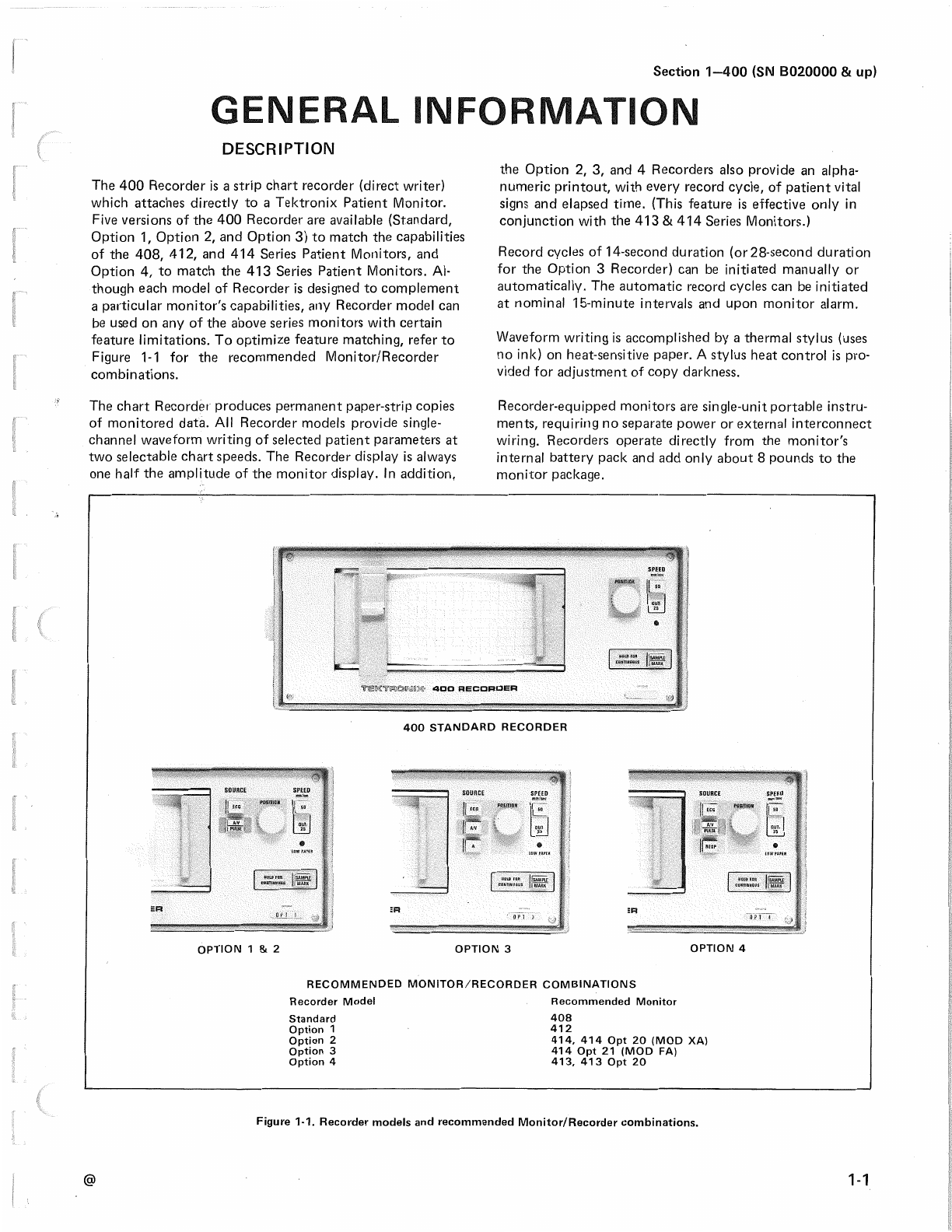
DESCRIPTION................................................................... 1-1
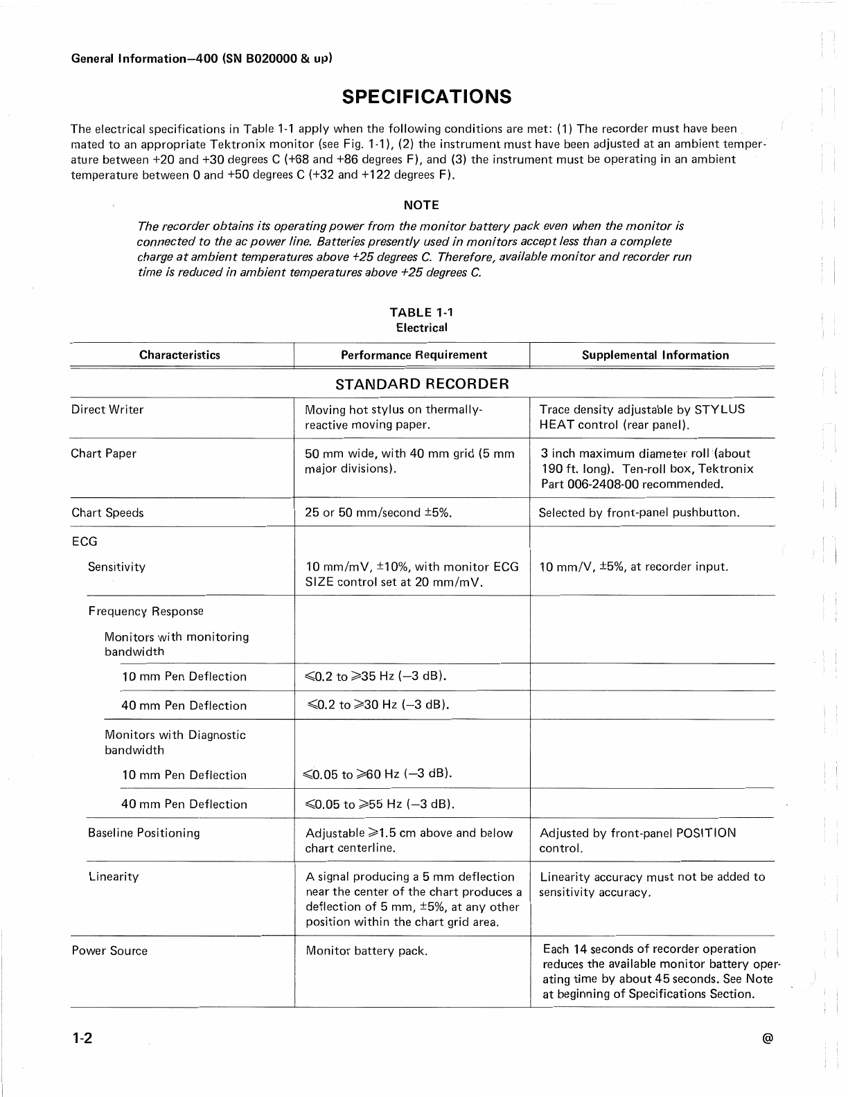
SPECIFICATIONS................................................................... 1-2
MOUNTING INFORMATION .................................................. 1-6
MOUNTING KIT ................................................................ 1-7
MOUNTING BRACKET ..................................................... 1-7
MOUNTING ADAPTER ..................................................... 1-7
RECORDERSUPPORT BLOCK ........................................ 1-7
SUPPLEMENTAL INFORMATION ......................................... 1-8
RUN CONTROL PROGRAMMABLE FUNCTIONS...........1-8
BATTERY DRAIN............................................................... 1-8
408/412/414 MONITOR/RECORDER ADAPTER
KIT INSTALLATION .............................................................. 1-10
INTRODUCTION.............................................................. 1-10
Battery-Pack Ordering lnformation .......................... 1-1O
INSTALLATION INSTRUCTIONS.................................... 1-10
A. Monitor Preparation ............................................. 1-1O
B. 408 Monitors ....................................................... 1-15
C. 412 Mod 735C Monitors ..................................... 1-15
D. 412 Monitors ....................................................... 1-15
E. 414 Monitors ........................................................ 1-17
F. 414 Option 21 (Mod FA) Monitors .....................1-19
G. 414 Option 20 (MOD XA) Monitors ...................1-21
H. Recorder Mounting and Checkout .....................1-22
413 MONITOR/RECORDER ADAPTER
KIT INSTALLATION .............................................................. 1-24
INTRODUCTION.............................................................. 1-24
Battery-Pack Ordering lnformation ..........................1-24
INSTALLATION INSTRUCTIONS.................................... 1-24
A. Monitor Preparation ............................................ 1-24
B. Recorder Mounting and Checkout ......................1-27
SECTION 2 OPERATING INFORMATION
HOW TO LOAD PAPER.................................................... 2-1
PAPER GRID FORMAT ..................................................... 2-1
PAPER USAGE RATE....................................................... 2-1
HOW TO ORDER PAPER................................................. 2-1
REMOTE AND AUTOMATIC STARTING (FIG. 2-4) .....,..2-3
Automatic .................................................................... 2-3
Remote ......................................................................... 2-3
HOW TO READ PRESSURERECORDINGS....................2-3
Alpha-Numeric Printing .............................................. 2-3
FUNCTIONS OF CONTROLS, CONNECTORS
& INDICATORS ................................................................. 2-5
Front Panel (Fig. 2-6) .................................................. 2-5
Rear Panel (Fig. 2-7) ................................................... 2-6
POWER.............................................................................. 2-6
Note About Battery Fuse: ........................................... 2-7
SECTION 3 THEORY OF OPERATION
RUN CONTROL BOARD ................................................... 3-1
PEN AMPLIFIER BOARD .................................................. 3-8
A CONDITIONER BOARD (OPTION 3 ONLY)................3-12
A/V BUFFER BOARD (OPTION 2 ONLY)......................3-14
A/V CONDITIONER BOARD (OPTION 3 ONLY) ...........3-15
DVM ANALOG AND DVM DIGITAL ..............................3-16
PRINT CONTROL 1 BOARD, PRINT CONTROL 2
BOARD, PRINT DRIVE BOARD...................................... 3-19
POWER SUPPLY BOARD............................................... 3-30
@
400 (SN 8020000 & up)
PAGE
SECTION 4 MAINTENANCE
PREVENTIVEMAINTENANCE ............................................... 4-1
CABINET REMOVAL. ....................................................... .4-1
CLEANING......................................................................... 4-1
Exterior ........................................................................ 4-1
Interior ......................................................................... 4-1
VISUAL INSPECTION...................................................... .4-2
SEMICONDUCTOR CHECKS........................................... .4-2
TROUBLESHOOTING ............................................................ .4-3
TROUBLESHOOTING AIDS .............................................. 4-3
Diagrams ..................................................................... 4-3
Circuit Board Illustrations ......................................... .4-3
Adjustment And Test Point Locations ....................... 4-3
Component Value Identification ................................ 4-3
Semiconductor Lead Configurations .........................4-3
Signal Routing Diagrams .......................................... .4-3
Truth Tables ................................................................ 4-3
Servicing Extender Set .............................................. .4-3
CORRECTIVE MAINTENANCE ................................. 4-5
SERVICE RECORD........................................................... .4-5
OBTAINING REPLACEMENT PARTS.............................. .4-5
Standard Parts ............................................................ 4-5
Special Parts ............................................................... 4-5
Ordering Parts ............................................................. 4-5
SOLDERING TECHNIQUES .............................................. 4-5
COMPONENT REMOVAL AND REPLACEMENT............4-5
Instrument Disassembly ............................................. 4-5
Pushbuttons ................................................................ 4-6
Interconnecting Cables and Terminal
Connectors .................................................................. 4-6
Semiconductors .......................................................... 4-6
Interconnecting Circuit-Board Pins ...........................4-6
Circuit Boards.............................................................. 4-9
Strip Chart Recorder Module ...................................4-14
PRINT HEAD ASSEMBLY (A16) ....................................4-16
RECOMMENDED PRINT HEAD ADJUSTMENT
PROCEDURE................................................................... 4-17
ALTERNATE PRINT HEAD ADJUSTMENT
PROCEDURE................................................................... 4-18
PEN MOTOR ................................................................... 4-18
Adjusting Stylus Tension Using A
Dynamometer ............................................................ 4-20
Adjusting Stylus Tension Without A
Dynamometer ............................................................ 4-20
Chart Drive Motor .................................................... .4-21
ADJUSTMENT AFTER REPAIR......................................4-22
SECTION 5 CALIBRATION
INTRODUCTION................................................................ 5-1
Purpose ........................................................................ 5-1
Calibration Interval ..................................................... 5-1
Partial Adjustment ...................................................... 5-1
Test Equipment Required ........................................... 5-1
FUNCTIONAL CHECK....................................................... 5-1
PRELIMINARY PROCEDURE FOR ADJUSTMENT.. ........5-2
OPTION 2, 3 AND 4 RECORDERADJUSTMENTS .........5-5
SECTION 6 REPLACEABLE ELECTRICAL PARTS
SECTION 7 DIAGRAMS AND CIRCUIT BOARD
ILLUSTRATIONS
SECTION 8 REPLACEABLE MECHANICAL PARTS
CHANGE INFORMATION

400 (SN 8020000 &
FIGURE
NO.
Frontis-
ii
piece
1-1
1-2
1-3
1-4
1-5
1-6
1-7
1-8
1-9
1-10
1-11
1-12
1-13
1-14
1-15
1-16
1-17
1-18
1-19
1-20
1-21
1-22
1-23
1-24
1-25
1-26
1-27
1-28
2-1
2-2
2-3
2-4
2-5
2-6
2-7
3-1
3-2
3-3
3-4
400 OPTION 4 Recorder with 413 Monitor ..
Recorder models and recommended Monitor/
Recorder combinations ............ .
Dimensional outline drawing ........ .
Installing mounting stand to tubular object
(pipe) or cabinet side ........... .
Installing mounting adapter to Monitor/
Recorder unit ............... .
Mounting Monitor/Recorder to mounting stand
Typical battery drain ............. .
Programming Run Control circuit ...... .
Typical 408,412, or 414 Monitor/Recorder
adapter kit installation ............ .
016-0498-00 Monitor/Recorder Adapter Kit
contents ................... .
Installing wire to 414 Main Board ..... .
Installing wire to 408 and 412 Main Board
Installing Manifold Board mounting bar ..
Installing wire to ECG Board ....... .
Installing Manifold Board and connecting
cable in 408 ................. .
Installing Manifold Board and connecting
cables in 412 735C ............. .
Installing 2-wire cable to 412 Pressure/Pulse
Board ..................... .
Installing Manifold Board and connecting
cables in 412 ................ .
Installing 5-wire cable to 414 Readout
Conditioner Board ............ .
Installing 2-wi re cable to 414 Pressure/Pulse
Board ................... .
Connecting white-red wire to -7 Von
414 Main Board ............. .
Installing Manifold Board and connecting
cables to 414 ............... .
Installing 5-wire cable to 414 Option 21
(MOD FA) Readout Conditioner Board .
Adding wire to 414 FA Dual-Pressure Board
Installing Manifold Board and connecting cables
in 414 Option 21 (MOD FA) ...... .
Installing 5-wire cable to 414 Option 20
(MOD XA) Readout Conditioner Board .
Installing Manifold Board and connecting
cables in 414 Option 20 (MOD XA) ....
413 Monitor/Option 4 Recorder adapter kit
installation ................... .
Contents of the 016-0638-00 monitor/recorder
Adapter Kit .................... .
I
Opening paper carriage ............... .
Proper routing of paper roll on Recorder carriage.
How to start recorder ......... .
Remote and automatic sample modes
Reading pressure recordings .....
Front-panel controls and indicators ..
Rear-panel controls and indicators ..
Location of circuit boards within the Recorder.
Start Power circuit operation .......... .
Stop Power circuit operation .......... .
Start Print initiated by any record sample mode
which has started the recorder .......... .
PAGE
.vi
. 1-1
.1-6
. 1-6
.1-7
.1-7
.1-8
. 1-9
. 1-11
. 1-12
. 1-13
. 1-13
. 1-14
. 1-14
. 1-15
. 1-16
. 1-16
. 1-17
. 1-18
. 1-18
. 1-19
. 1-19
. 1-20
. 1-20
. 1-21
. 1-22
. 1-23
. 1-25
. 1-26
.2-1
.2-1
.2-2
.2-3
.2-4
.2-5
.2-6
.3-2
.3-4
.3-5
.3-6
FIGURE
NO.
3-5
3-6
3-7
3-8
3-9
3-10
3-11
3-12
3-13
3-14
3-15
4-1
4-2
4-3
4-4
4-5
4-6
4-7
4-8
4-9
4-10
4-11
5-1
5-2
I
Start Print initiated by SAMPLE/MARK being held
in then released after run time and print cycle
have ended ...................... .
Start Print initiated by pushing SAMPLE/MARK
after print ends but before run time ends
Timing diagram for normal run cycle ...
Timing diagram for in-process run cycle
interrupted by an alarm ......... .
Timing diagram for continuous-run cycle,
initiated by SAMPLE/MARK button.
Systolic/Diastolic switching points .
Basic AID dual-slope waveform ... .
ASC 11character code ......... .
Interpreting Word Address PROMs addresses
Interpreting Word-to-Character PROMs addresses.
Chart drive motor voltage waveform . . . . ... .
Color code for resistors and capacitors ...... .
Installation and orientation of terminal connectors.
Semiconductor lead configurations ....... .
Exploded-view of circuit-board pin and ferrule .
Location of battery pack plug P2130 in the
Monitor ...................... .
Location of circuit boards within the Recorder.
Location of screws securing A4-Power Supply
circuit board .................... .
Proper dress of the Print Head Flex Cable ... .
Location of securing screws and tension-adjusting
screw for the Print Head Assembly .
Stylus replacement .............. .
Stylus tension adjusting tool. ........ .
Connecting square wave to -ECG wave input
Temperature Simulation Plugs........ .
PAGE
.. 3-7
.3-8
.3-9
. 3-10
. 3-11
. 3-14
. 3-17
. 3-21
. 3-22
. 2-26
. 3-31
.4-4
.4-6
.4-7
.4-9
. 4-10
. 4-11
. 4-12
. 4-15
. 4-16
. 4-20
. 4-21
.5-4
.5-6
The illustrations in Section 7-1 are located near their associated
diagrams on the foldout pages.
7-1 Semiconductor Lead configurations.
7-2 Circuit board locations.
7-3 IC Truth Tables.
7-4 A2-Run Control Board components.
7-5 Programming Run Control circuit.
7-6 A3-Pen Amplifier Board components.
7-7 A 10-A Conditioner Board components.
7-8 A8-A/V Buffer Board components .
7-9 A9-A/V Conditioner Board components.
7-10 A11-DVM Anal·og Board components.
7-11 A12-DVM Digital Board components.
7-12 A 13-Print Control 1 Board components.
7-13 A 14-Print Control 2 Board components .
7-14 A 15-Print Drive Board components .
7-15 A4-Power Supply Board component locations .
7-16 A 1-Motherboard component locations .
7-17 A7-Manifold Board connector locations.
7-18 Monitor/Recorder Signal Interconnections
(408,412, 412-735C) .
7-19 Monitor/Recorder Signal Interconnections
(413, 413/OPT 20).
7-20 Monitor/Recorder Signal Interconnection
414 OPT 21 MOD FA, 414 OPT 20 (MOD XA), 414.
7-21 Adjustment and Test-Point locations.
@

400 (SN 8020000 & up)
LI T F ABLES
TABLE TABLE
NO. PAGE NO. PAGE
1-1 Electrical. . . . . . . . . . . . . .. 1-2 3-2 Word Address PROMs Contents .... . 3-23
1-2 Environmental Characteristics. .1-5 3-3 Word-to-Character PROMs Contents . . 3-27
1-3 Physical Characteristics ..... .1-5 4-1 Routine Maintenance Schedule , , , , ' .4-1
1-4 Factory Programmed Run-Control Functions. .1-8 4-2 Circuit Boards Installed in Your Recorder . .. 4-9
2-1 Alpha-Numerics Available with Various 4-3 P388 Wire Locations . . 4-19
Monitor/Recorder Units ........ .2-4 4-4 P2034 Wire Locations . 4-19
3-1 Input/Output Combinations of U830 . 3-18 5-1 Test Equipment .... . .5-1
@ iii

400 (SN B020000 & up)
SAFETY INFORMATION
This manual contains safety information which you as the user must follow to ensure safe operation of the Monitor/Recorder
unit. Refer to the appropriate manual for safety information on the specific monitor used with your Recorder. WARNING
information is intended to protect the patient and the operator, and CAUTION information is intended to protect the instru-
ment. The following general safety precautions, which do not appear elsewhere in this publication, must be applied during all
phases of operation and maintenance.
WARNING I
UseOnly With Tektronix Model 408,412,413, or 414 Monitor
Do not operate this Recorder in conjunction with any monitor other than those for which it wasspecifically designed (the
Tektronix Model 408,412,413, or 414 Monitors). To do so could result in unsafe operation of the Monitor/Recorder unit.
Only a Tektronix Field Service Center or other qualified service personnel should mate the Recorder to the Monitor unit.
Do Not Operate Monitor/Recorder in an ExplosiveAtmosphere
Do not operate the Monitor/Recorder unit in the presence of flammable gasesor anesthetics. Explosion can result from
operation in such an environment. Safety document NFPA 56A, Standard for the Useof Inhalation Anesthetics, paragraphs
24114(c) and 24032, states that with the appropriate precautions, portable electronic equipment may safely be operated at
five feet (or more) above the floor in anesthetic locations.
UseAC Outlet with Protective-Ground Contact
The Monitor/Recorder unit is compatible with isolated power systems as used in operating rooms. In non-isolated power
systems, this Monitor/Recorder unit is intended to be operated from a single-phase,earth-referenced power source having one
current-carrying conductor (the neutral or grounded conductor) near earth potential. Operation from power sources where
both current-carrying conductors are live with respect to earth (such asphase-to-phase on a three-wire system) is not recom-
mended, since only the line (or ungrounded) conductor has over-current (fuse) protection within the unit.
The unit has a three-wire (18-gauge,SJT grade) power cord and is normally supplied with a three-terminal polarized plug
(Hospital Grade) for connection to the power source and protective ground. The ground (earth) terminal of the plug is
directly connected to the frame of the Monitor/Recorder unit. For electric-shock protection, insert this plug only in a mating
'Hospital Grade'power outlet with aprotective-ground contact. Do not defeat the grounding connection. Any interruption of
the grounding connection can create an electric-shock hazard.
Inspect the power cord periodically for fraying or other damage. Do not operate the Monitor/Recorder unit from an ac power
source if the power cord or plug is damaged.
UseOnly Safe Methods of Interconnection
To ensure protection against electric shock from the Monitor/Recorder cabinet whenever auxiliary, line-operated equipment
is electrically connected to the unit, the Monitor/Recorder unit must be properly grounded. When the monitor is connected
to other line-operated equipment, battery operation should be avoided. If it cannot be avoided, the unit must be grounded
using the terminal provided on the rearpanel of the monitor. It is extremely important that equipment interconnections are
made in accordance with NFPA 768-T, Tentative Standard for the Safe Use of Electricitv in Patient CareAreas of Health
CareFacilities, section 3038, 'Signal Transmission Between Appliances~
Do Not Remove Instrument Covers
High voltage ispresent inside the monitor. To avoid electric-shock hazard, operating personnel must not remove the protec-
tive instrument covers. Component replacement and internal adjustments must be made by qualified service personnel only.
Do Not Touch Writing Stylus
Do not touch the writing stylus during Recorder operation because the stylus becomes very hot and may cause burns.
iv @

400 (SN 8020000 & up)
~
Protect the Monitor/Recorder From Foreign Material
Do not insert any object (such as hand, tool, etc.), or allow any foreign material to fall into the opening in the front of the
Recorder, as this can cause damage to the electronic components of the unit.
Monitor Mounting Adapter
When a Monitor/Recorder is attached to a pole or other support, a plastic support block must be in place on the side of the
Recorder under the monitor mounting adapter. Thissupport block, attached to the Recorder at the time of manufacture,
provides proper mechanical alignment for the mounting adapter. The Monitor/Recorder mounting fixture design intends that
the monitor mounting adapter be used ONLY with the support block installed on the Recorder. See mounting instructions
in GeneralInformation Section.
Additional safety information can be found in the following documents:
@
(1) Canadian Standards Association C22.2, No. 125, Electro-Medical Equipment. 1973.
(2) National Fire Protection Association:
NFPA 56A. Standard for the Use of Inhalation Anesthetics. 1973.
NFPA 70. National Electrical Code (Article 517). 1975.
NFPA 76B-T, Tentative Standard for the Safe Use of Electricity in Patient Care Areas of Health Care
Facilities. 1973.
(3) Underwriters' Laboratories, Inc:
U.L. 544. Standard for Safety. Medical and Dental Equipment, 1974.
V

400 (SN B020000 & up)
I I
2429-1
400 OPTION 4 Recorder with 413 Monitor.
vi @

GENE L INF
DESCRIPTION
The 400 Recorder is a strip chart recorder (direct writer)
which attaches directly to a Tektronix Patient Monitor.
Five versions of the 400 Recorder are available (Standard,
Option 1, Option 2, and Option 3) to match the capabilities
of the 408, 412, and 414 Series Patient Monitors, and
Option 4, to match the 413 Series Patient Monitors. Al-
though each model of Recorder is designed to complement
a particular monitor's capabilities, any Recorder model can
be used on any of the above series monitors with certain
feature limitations. To optimize feature matching, refer to
Figure 1-1 for the recommended Monitor/Recorder
combinations.
The chart Recorder produces permanent paper-strip copies
of monitored data. All Recorder models provide single-
channel waveform writing of selected patient parameters at
two selectable chart speeds. The Recorder display is always
one half the amplitude of the monitor display. In addition,
Section 1-400 (SN 8020000 & up)
TION
the Option 2, 3, and 4 Recorders also provide an alpha-
numeric printout, with every record cycle, of patient vital
signs and elapsed time. (This feature is effective only in
conjunction with the 413 & 414 Series Monitors.)
Record cycles of 14-second duration (or28-second duration
for the Option 3 Recorder) can be initiated manually or
automatically. The automatic record cycles can be initiated
at nominal 15-minute intervals and upon monitor alarm.
Waveform writing is accomplished by a thermal stylus (uses
no ink) on heat-sensitive paper. A stylus heat control is pro-
vided for adjustment of copy darkness.
Recorder-equipped monitors are single-unit portable instru-
ments, requiring no separate power or external interconnect
wiring. Recorders operate directly from the monitor's
internal battery pack and add only about 8 pounds to the
monitor package.
400 STANDARD RECORDER
@
OPTION 1 & 2
SOURCE
ER
OPTION 3 OPTION 4
RECOMMENDED MONITOR/RECORDER COMBINATIONS
Recorder Model
Standard
Option 1
Option 2
Option 3
Option 4
Recommended Monitor
408
412
414, 414 Opt 20 (MOD XA)
414 Opt 21 (MOD FA)
413, 413 Opt 20
Figure 1-1. Recorder models and recommended Monitor/Recorder combinations.
1-1

General Information-400 (SN B020000 & up)
SPECIFICATIONS
The electrical specifications in Table 1-1 apply when the following conditions are met: (1) The recorder must have been
mated to an appropriate Tektronix monitor (see Fig. 1-1), (2) the instrument must have been adjusted at an ambient temper-
ature between +20 and +30 degrees C (+68 and +86 degrees F), and (3) the instrument must be operating in an ambient
temperature between 0 and +50 degrees C (+32 and +122 degrees F).
NOTE
The recorder obtains its operating power from the monitor battery pack even when the monitor is
connected to the acpower line. Batteries presently used in monitors accept less than a complete
charge at ambient temperatures above +25 degrees C. Therefore, availablemonitor and recorder run
time is reduced in ambient temperatures above +25degrees C.
Characteristics
Direct Writer
Chart Paper
Chart Speeds
ECG
Sensitivity
Frequency Response
Monitors with monitoring
bandwidth
10 mm Pen Deflection
40 mm Pen Deflection
Monitors with Diagnostic
bandwidth
10 mm Pen Deflection
40 mm Pen Deflection
Baseline Positioning
TABLE 1-1
Electrical
Performance Requirement
STANDARD RECORDER
Moving hot stylus on thermally-
reactive moving paper.
50 mm wide, with 40 mm grid (5 mm
major divisions).
25 or 50 mm/second ±5%.
10 mm/mV, ±10%, with monitor ECG
SIZE control set at 20 mm/mV.
<0.2 to ~35 Hz (-3 dB).
<0.2 to ~30 Hz (-3 dB).
<0.05 to ~60 Hz (-3 dB).
<0.05 to ~55 Hz (-3 dB).
Adjustable ~1.5 cm above and below
chart centerline.
Supplemental Information
Trace density adjustable by STYLUS
HEAT control (rear panel).
3 inch maximum diameter roll (about
190 ft. long). Ten-roll box, Tektronix
Part 006-2408-00 recommended.
Selected by front-panel pushbutton.
10 mm/V, ±5%, at recorder input.
Adjusted by front-panel POSITION
control.
Linearity A signal producing a 5 mm deflection Linearity accuracy must not be added to
near the center of the chart produces a sensitivity accuracy.
deflection of 5 mm, ±5%, at any other
position within the chart grid area.
Power Source Monitor battery pack. Each 14 seconds of recorder operation
reduces the available monitor battery oper
ating time by about 45 seconds. See Note
at beginning of Specifications Section.
1-2 @

Characteristics
Record Sample Activation
Manual
Timed Interval
Alarm
Identification Mark
General lnformation-400 (SN B020000 & up)
TABLE 1-1 (CONT.)
Electrical
Performance Requirement
'
14-second, ± 1.4 second, sample
manually started by SAMPLE/MARK
push button or by remote contact
closure connected to the rear-panel
REMOTE SAMPLE/MARK jack.
Rear-panel pushbutton allows recorder to
initiate a record sample every 15 minutes,
±2 minutes.
Rear-panel pushbutton causes a 14
second record sample to be taken
automatically when the monitor in-
dicates an alarm.
5 mm (-2, +4 mm), 40 ms (±15 ms)
rectangular pulse.
OPTION 1 RECORDER
Supplemental Information
Records continuously as long as
SAMPLE/MARK pushbutton is held in
or remote contacts remain closed, plus
14 seconds after release.
Other time intervals can be selected
by P136. See Figure 1-7.
Pulse rises above trace when SAMPLE/
MARK pushbutton is pressed while
recorder is running.
Specifications for Option 1 Recorder are sameas those for Standard Recorder plus the following:
Pressure/Pulse Selected by SOURCE pushbutton
switch marked A/V /PULSE.
A=Arterial, V=Venous.
Pressure Sensitivity
414 412 Pen Deflection:
250 (250) 5 mm per 50 (50) mmHg, ±5%
150 (125) 5 mm per 30 (25) mmHg, ±5%
25 ( 50) 5 mm per 5 (10) mm Hg, ±5%.
Frequency Response
Pressure De to about 20 Hz.
Pulse 0.1 Hz to about 20 Hz.
Baseline Positioning A zero volt pressure signal applied to
monitor produces a trace 5 mm, ±1 mm,
above bottom line of chart.
OPTION 2 RECORDER
Specifications for Option 2 Recorders are same asthose for Standard and Option 1 Recorders, plus the following:
Alpha-numeric Printout
@
Elapsed time, heart rate, blood pressure,
temperature, and respiration printed along
top margin of chart. When the monitor
determines that a parameter is overranging,
the recorder prints asterisks in place of
the parameter. Parameters printed vary
according to monitor type.
1-3
j

General lnformation-400 (SN B020000 & up)
Characteristics
Elapsed Time (ET)
Heart Rate (RATE)
Blood Pressure (BP A/V) 1
Temperature (TEMP A and/or
TEMP B)
Respiration (RESP)
Alarm
Overrange
Deviation from Monitor Readout
TABLE 1-1 (CONT.)
Electrical
Performance Requirement
Prints out in hours and minutes to 9:59,
then repeats. Accurate to ±1 minute in 10
hours. Timing begins from zero when the
first sample is taken following monitor
turn-on.
Prints out in beats/minute. Accurate to
±3 bpm at 60 and ±5 bpm at 250 of
monitor input.
Prints out in millimeters of mercury
(mmHg). Accurate to ±5 mm Hg of
monitor input.
Prints out in ° C or° F as specified by
monitor. Accurate to ±0.3° C or ±0.5° F
over a range of +5° to +45° C or 41 ° to
113° F for instrument ambient tempera-
ture between +15° and +35° C. Accuracy
is ±0.5° C or ±0.9° F over same range for
instrument ambient temperature between
0° and +50° C.
Prints out in breaths per minute. Accurate
to ±3 bpm at 30 and ±5 at 120 of input
to monitor.
Prints out the word ALARM at the end of
print sequence when monitor is in an
alarm state.
When monitor determines that a param-
eter is in overrange, the recorder prints
asterisks in place of parameter values.
±5 counts maximum.2
OPTION 3 RECORDER
Supplemental Information
Derived from ECG, pressure or pulse
channel as determined by monitor.
Prints systolic, diastolic and mean
pressure values. A minus sign is printed
for negative pressure values.
With Yellow Springs Instrument Co.
Series 700 probes. Temperature print-
out is eliminated when temperature
probe is disconnected.
Printout range, -5° to +45° C or
+23° to +113° F.
Monitor derives respiration from its
ECG channel.
Specifications for Option 3 Recorders are same asthose for Standard, Option 1, and Option 2 Recorders, plus the following:
Record Sample Time
Blood Pressure (BPA)
28, ±2.8 seconds, or until printout com-
plete. Printout starts 14, ±1.4 seconds
after sample is initiated.
Prints out in millimeters of mercury
(mmHg). Accurate to ±5 mmHg of mon-
itor input. Pressure value settles to ±3
counts of final reading, 10 seconds after
a pressure change occurs.
Set at P182 on Run Control board.
Prints systolic, diastolic and mean
pressure values for Channel A and then
Channel A/V. Printout is eliminated if
pressure transducer is disconnected
from monitor. A minus sign is printed
for negative pressure values.
1 The pressure channel of single pressure 414 Monitors (414,414 GA, etc.) is always on, except in PULSE mode. When no pressure transducer
is connected to the monitor, the pressure channel "floats" causing the recorder to print invalid blood pressure values.
2With instrument operating in an ambient temperature range of +15°C to +35°C.
1-4 @
' !

Characteristics
TABLE 1-1 (CONT.)
Electrical
Performance Requirement
OPTION 4 RECORDER
General lnformatfon-400 (SN 8020000 & up)
Supplemental Information
Specifications for Option 4 Recorders are same asthose for Standard, Option 1, and Option 2 Recorders, plus the following:
Respi ration
Sensitivity
Frequency Response (-3 dB)
Ambient Temperature
Operating
Non-operating
Altitude
Weight
Characteristics
Characteristics
Standard and Option 1
Option 2, 4
Option 3
Height
Recorder with Feet
Monitor/Recorder with Feet
Width
1 ohm change in input to monitor pro-
duces a 10 mm (±2.5 mm) pen deflection,
with monitor Respiration Size control
set to calibrated position.
0.1 Hz or less, to at least 4 Hz.
TABLE 1-2
Environmental Characteristics
Monitor derives respiration signal from
a changing ac impedance between LA
and RA ECG leads. See monitor
manual.
Performance Requirement
0 to +50 degrees C (+32 to +122 degrees F). See battery-
capacity note at beginning of Specifications section.
-40 to +60 degrees C (-40 to +140 degrees F).
To 15,000 feet.
TABLE 1-3
Physical Characteristics
7.5 lb (3.4 kg).
8.5 lb (3.86 kg.)
8.6 lb (3.9 kg.)
4.06 inches (10.3 cm).
10 inches (25.6 cm).
9 inches (23.1 cm).
Description
Depth (including cord wraps and knob protrusions). 11.7 inches (29.8 cm).
@ 1-5

General lnformation-400 (SN B020000 & up)
10"
(25.6 CM) 1-
1
4.06" ----
(10.3 CM)
~-l__J.______9_" L_J_1_l__1-~11.7"
(23.1 CM)~ .......I --------(29.8 CM)
(2145-31)2429-;
1-6
Figure 1-2. Dimensional outline drawing.
MOUNTING INFORMATION
The following accessories are available for mounting the Monitor/Recorder unit on a pole.
PIPE OR OTHER
TUBULAR OBJECT
~
MOUNTING
STAND
Figure 1-3. Installing mounting stand to tubular object (pipe) or cabinet side.
2042-24
@

MOUNTING KIT
lnc::ludes Mounting Stand to mount Monitor/Recorder at
five-foot level. Attaches to vertical pipes or surfaces of anes-
thesia machines or similar devices.
Tektronix Part 016-0110-00
MOUNTING BRACKET
Attaches to top of Mounting Stand. Mates with Mounting
Fixture below.
Tektronix Part 407-1767-00
MOUNTING ADAPTER
Attaches to monitor. Mates with Mounting Bracket above.
(Included with monitor as a standard accessory.)
@
THESE SCREWS ADJUST
CLUTCH TENSION
Tektronix Part 014-0054-00
2042-25
Figure 1-4. Installing mounting adapter to Monitor/Recorder unit.
General Information-400 (SN B020000 & up)
RECORDER SUPPORT BLOCK
Attaches to recorder. Provides proper mechanical alignment
for the mounting adapter. (Attached to recorder at factory.}
C
Tektronix Part 391-0147-00
\
MOUNTING
BRACKET
(2042-26)2145-50
Figure 1-5. Mounting Monitor/Recorder to mounting stand.
1-7

General lnformation-400 (SN B020000 & up)
SUPPLEMENTAL INFORMATION
RUN CONTROL
PROGRAMMABLE FUNCTIONS BATTERY DRAIN
Each model of recorder is shipped from the factory with
the Run Control circuitry pre-programmed to operate opti-
mally for its intended use. Table 1-4 shows how each re-
corder model is set at the factory. Figure 1-7 shows what
run-control functions are available and how to make a
change if desired.
Figure 1-6 is a curve showing typical current taken from the
monitor battery during recorder operation.
4A
~25 ms~-+-- 400 ms~
2A
3 A WHEN PRINTING
OPTION 2, 3, AND 4 ONLY
(
,,--------
1 \
I I
I I
I I
2mA 2mA
0---------------......,____..,..._________....,.__
0 1 sec 1.25 sec 10 sec
10 sec (OPT. 3) 20 sec (OPT. 3)
(2145-37) 2429-4
Figure 1-6. Typical battery drain.
TABLE 1-4
Factory Programmed Run-Control Functions
Automatic Sample
Run Timer Interval Timer
Alpha-Numerics
Waveform Printed Printed at
Print P182 P136 At Selected Selected
Recorder Model Run Time Delay Jumpers Interval Ju'mpers Chart Speed Chart Speed P203 Jumpers
Standard 14 sec NA Pins 1-2 15 min Pins 3-7 X NA Pins 1-2
& 5-7
Option 1 14 sec NA Pins 1-2 15 min Pins 3-7 X NA Pins 1-2
& 5-7
Options 2, 4 14 sec 1.75 sec Pins 1-2 15 min Pins 3-7 X X Pins 1-2
& 5-7
Option 3 28 sec 14 sec Pins 1-5 15 min Pins 3-7 X X Pins 1-2
&6-7
1-8 @

@
P136
PIN 7-OUTPUT
6-120 MIN
5-60 MIN
4-30 MIN
3-15 MIN
2-7.5 MIN
1-3.75 MIN
EXAMPLE: IF JUMPER
IS INSTALLED BETWEEN
PINS 7 & 4, AUTOMATIC-
SAMPLE-MODE TIMED
INTERVAL WILL BE
30 MINUTES.
NORMAL STRAPPING IS
PINS 7TO 3.
P203
EFFECTIVE FOR TIMED
INTERVAL RUNS ONLY.
PINS 2 TO 1: WAVEFORM
AND ALPHANUMERICS
PRINTED AT SSELECTED
CHART SPEED. THIS IS
NORMAL STRAPPING.
PINS 2 TO 3:
ALPHANUMERICS ONLY
PRINTED AT 25 mm/SEC
CHART SPEED.
General lnformation-400 (SN 8020000 & up)
PIN 7-RUN TIMER COMMON
6-28 SEC
5-14 SEC
4-7 SEC
3-3.5 SEC
2-1.75 SEC
1-PRINT DELAY COMMON
P182
EXAMPLE: IF JUMPERS ARE
CONNECTED BETWEEN PINS 1 &
3 AND 4 & 7, RUN TIME WILL BE
7 SECONDS AND PRINT DELAY
WILL BE 3.5 SECONDS.
NORMAL STRAPPING FOR
OPTION 3 IS PINS 1 TO 5
AND 6 TO 7. ALL OTHER
RECORDERS ARE STRAP-
PED PINS 1 TO 2 AND 5
TO 7.
-+--BLUE iii-RED
A 2 3 4 s 6 7
I I
I I
I
>-thihlbdnbrhIh
1 2 3 4 5 6 7
P136
WAVEFORM
PRINTED AT
SELECTED
CHART SPEED
....-BLACK
I I
.4234567
I I
)>- cbdubcbduhcb
1 2 3 4 5 6 7
P182
1MnhP203*
"
ALPHA-NUMERICS
ONL V PRINTED AT
25 mm/SEC CHART
SPEED
RUN CONTROL BOARD
*PINS 1 & 3 MAY BE INTERCHANGED ON EARLY BOARDS.
TO CHANGE JUMPERS:
1. FOLD BACK HINGED
PORTION OF HOLDER.
2. MOVE CONNECTORS
TO DESIRED POSITIONS
WITH CRIMPED SIDE
TOWARD HINGE.
3. SNAP HOLDER ONTO
CONNECTORS.
Figure 1-7. Programming Run Control circuit.
P189
PINS 2 TO 4: RUN
TIME ON ALARM AS
STRAPPED IN P182.
THIS IS NORMAL
STRAPPING. PINS 2
TO 1: RUNS CON-
TINUOUSLY WHEN
MONITOR IS IN
ALARM.
PINS 2 TO 3: NOT
USED.
(2145-33) 2429-5
1-9

General lnformation-400 (SN B020000 & up)
408/412/414 MONITOR/RECORDER ADAPTER KIT INSTALLATION
NOTE
It is intended that this kit be installed only by Tektronix Service personnel.
INTRODUCTION
To join a 400 Series Recorder to any Tektronix 408,412,
or 414 Monitor, the following items must be at hand:
1. A 408,412, or 414 Monitor.
2. A 400 Recorder.
3. An 016-0498-00 Adapter Kit, which contains sufficient
electrical and mechanical parts to connect any option re-
corder to a 408, 412, or 414 monitor. This kit is shipped
with all recorders except the Option 4.
4. A monitor battery pack manufactured subsequent to
summer 1976. These packs have heavy cell interconnects, a
fusing arrangement, and a special connector which provides
power to the recorder. If needed, this battery pack must be
ordered separately.
Battery-Pack Ordering Information
All monitors mated to alpha-numeric printing recorders
(Options 2, 3, 4) must have F-cell battery packs for satis-
factory operation. D-cell packs, although not recommended,
can be used in a monitor mated to Standard or Option 1
recorders. However the result is about 50% less operating
time. Select the appropriate battery pack from the list below.
To replace with Order Tektronix Part No.
D-cells D-cells 119-0441-01
D-cells F-cells 040-0710-01
F-cells F-cells 119-0443-01
F-cells D-cells Not recommended
Figure 1-8 shows a typical 408, 412, or Monitor/Recorder
installation. These steps summarize the installation
procedure.
1. A -01 battery pack is installed in the monitor (providing
it doesn't already have a battery pack, or its pack does not
have provision for recorder operation).
1-10
NOTE
If a new battery pack is to be installed, the re-
sistor which determines battery chargingcurrent
may need to be replaced. Instructions and the
proper resistor arepackaged with each new
battery pack.
2. A Manifold Board is installed in the monitor. This is the
interconnection point between various monitor models and
the recorder.
3. The necessary cables are connected from the monitor
internal circuitry to the Manifold Board.
4. A multi-conductor ribbon cable is connected between
the Manifold Board and the Recorder.
5. The monitor and recorder are joined mechanically and
tested.
INSTALLATION INSTRUCTIONS
A. Monitor Preparation
NOTE
Check off each step as you complete it.
1. Check contents of Adapter Kit. Check that you have all
the components before beginning. See Figure 1-9.
2. Obtain a Service Manual for your monitor. You will have
to refer to it later in these instructions.
3. Prepare Monitor.
a. Disconnect monitor from ac power source.
b. Remove top cover. Remove two screws on each side.
Lift up left side of cover, make sure it has cleared the
ECG LEAD CHECK terminals, and remove cover from
the monitor.
c. Remove bottom cover. Remove two screws on each
side and pull cover straight off.
d. Unplug the battery cable connector P711 from the
main board. You will be instructed to reconnect it in a
later step.
@

General Information-400 (SN 8020000 & up)
2429-12
Figure 1-8. Typical 408, 412, or 414 Monitor/Recorder adapter kit installation.
i~~l
Do not short cells. Nickel-cadmium cellsare
capable of delivering high currents which can
cause wire insulation to melt.
4. If necessary, replace battery pack with new one which
has been adapted for recorder use. See list of battery packs
in the introductory portion of these instructions. Do not
connect either the recorder or monitor battery connector
until instructed to do so.
@
~
Most of the monitor and recorder circuits can
be damagedby the dischargeof static electricity
into them. The damage may not become ap-
parent for several months. Before proceeding,
review and adhere to the Recommended Handl-
ing Rules on page 4-8.
5. Install white-violet wire (with violet connector) on main
board. See Figure 1-10 for 414 Monitors or Figure 1-11 for
408 and 412 Monitors.
1-11

General lnformation-400 (SN B020000 & up)
TEKTRONIX
PART NO.
386-3601-00
175-1984-00
211-0542-00
381-0379-00
211-0014-00
210-0004-00
129-0123-00
211-0008-00
670-4754-00
TEKTRONIX
PART NO.
006-0531-00
2"-#26
INSULATED
WIRE
175-1986-00
175-1968-00
195-0187-00
175-1969-00
195-0169-00
175-1965-00
175-1966-00
175-1970-00
195-0171-00
1-12
QUANTITY
2
8
2
2
2
2
QUANTITY
2
l
ABOVE COMPONENTS FOR 408,412,414 MONITORS
408
•
•
•
412-
735C
•
•
•
412
•
•
•
•
414
•
•
•
•
•
•
•
•
414
FA
•
•
•
•
•
•
•
•
SELECT THESE COMPONENTS
FOR YOUR PARTICULAR MONITOR
(2145-1) 2429-67
Figure 1-9. 016-0498-00 Monitor/Recorder Adapter Kit contents.
@
This manual suits for next models
5
Table of contents
Other Tektronix Medical Equipment manuals
Popular Medical Equipment manuals by other brands

Otto Bock
Otto Bock Genium Protector 4X880 Series Instructions for use

DJO Global
DJO Global Aircast VenaFlow Elite S manual

Huntleigh
Huntleigh AKRON 3 SECTION DRAINAGE Service manual

College Park
College Park venture Technical instructions

Nestle Health Science
Nestle Health Science Compat ella Instructions for use

Ofa Bamberg
Ofa Bamberg Dynamics Knee immobilisationsplint Important notes