HT HT65 User manual

Copyright HT ITALIA 2020 Release EN 1.00 - 10/02/2020
ENGLISH
User manual

HT65
EN - 1
TABLE OF CONTENTS
1.PRECAUTIONS AND SAFETY MEASURES ...............................................................2
1.1.Preliminary instructions ..................................................................................................... 2
1.2.During use......................................................................................................................... 3
1.3.After use............................................................................................................................ 3
1.4.Definition of Measurement (Overvoltage) category........................................................... 3
2.GENERAL DESCRIPTION ...........................................................................................4
2.1.Measuring average values andTRMS values.................................................................... 4
2.2.Definition of true root mean square value and Crest factor............................................... 4
3.PREPARATION FOR USE ...........................................................................................5
3.1.Initial checks...................................................................................................................... 5
3.2.Instrument power supply ................................................................................................... 5
3.3.Storage.............................................................................................................................. 5
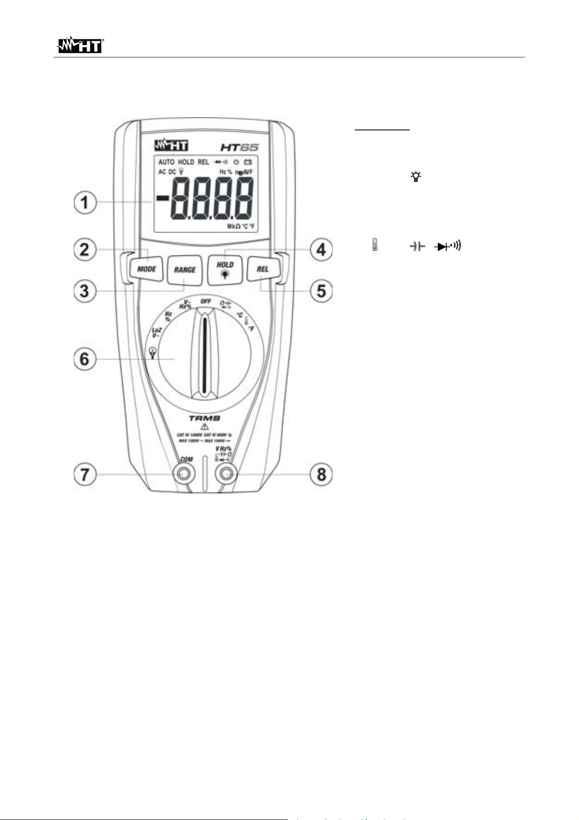
4.NOMENCLATURE........................................................................................................6
4.1.Description of the instrument............................................................................................. 6
4.2.Description of function keys .............................................................................................. 7
4.2.1.HOLD/ key ............................................................................................................................. 7
4.2.2.RANGE key ................................................................................................................................ 7
4.2.3.REL key ...................................................................................................................................... 7
4.2.4.MODE key .................................................................................................................................. 7
4.2.5.LoZ feature ................................................................................................................................. 7
4.2.6.Disabling the Auto Power Off function........................................................................................ 7
5.OPERATING INSTRUCTIONS.....................................................................................8
5.1.DC Voltage measurement ................................................................................................. 8
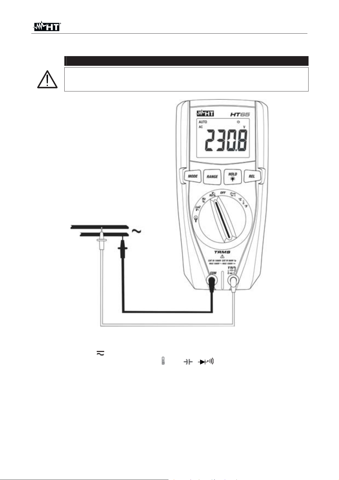
5.2.AC Voltage measurement ................................................................................................. 9
5.3.AC/DC Voltage measurement with low impedance (LoZ) ............................................... 10
5.4.Frequency and Duty Cycle measurement ....................................................................... 11
5.5.Resistance measurement and Continuity test................................................................. 12
5.6.Diode test ........................................................................................................................ 13
5.7.Capacitance measurement ............................................................................................. 14
5.8.Temperature measurement with K-type probe................................................................ 15
5.9.DC Current measurement with transducer clamps ......................................................... 16
5.10.AC Current measurement with transducer clamps.......................................................... 17
6.MAINTENANCE .........................................................................................................18
6.1.Replacing battery ............................................................................................................ 18
6.2.Cleaning the instrument .................................................................................................. 18
6.3.End of life ........................................................................................................................ 18
7.TECHNICAL SPECIFICATIONS ................................................................................19
7.1.Technical characteristics ................................................................................................. 19
7.1.1.Reference standards ................................................................................................................ 21
7.1.2.General characteristics............................................................................................................. 21
7.2.Environment .................................................................................................................... 22
7.2.1.Environmental conditions for use ............................................................................................. 22
7.3.Accessories..................................................................................................................... 22
7.3.1.Accessories provided ............................................................................................................... 22
7.3.2.Optional accessories ................................................................................................................ 22
8.ASSISTANCE.............................................................................................................23
8.1.Warranty conditions......................................................................................................... 23
8.2.Assistance....................................................................................................................... 23

HT65
EN - 2
1. PRECAUTIONS AND SAFETY MEASURES
The instrument has been designed in compliance with directive IEC/EN61010-1 relevant to
electronic measuring instruments. For your safety and in order to prevent damaging the
instrument, please carefully follow the procedures described in this manual and read all
notes preceded by symbol with the utmost attention.
Before and after carrying out measurements, carefully observe the following instructions:
xDo not carry out any measurement in humid environments.
xDo not carry out any measurements in case gas, explosive materials or flammables are
present, or in dusty environments.
xAvoid any contact with the circuit being measured if no measurements are being
carried out.
xAvoid any contact with exposed metal parts, with unused measuring probes, circuits,
etc.
xDo not carry out any measurement in case you find anomalies in the instrument such
as deformation, breaks, substance leaks, absence of display on the screen, etc.
xPay special attention when measuring voltages higher than 20V, since a risk of
electrical shock exists.
In this manual, and on the instrument, the following symbols are used:
Warning: observe the instructions given in this manual; improper use could
damage the instrument or its components.
Double-insulated meter
AC voltage or current
DC voltage or current
Connection to earth
1.1. PRELIMINARY INSTRUCTIONS
xThis instrument has been designed for use in environments of pollution degree 2.
xIt can be used for VOLTAGE and CURRENT measurements on installations with CAT
IV 600V and CAT III 1000V.
xWe recommend following the normal safety rules devised by the procedures for
carrying out operations on live systems and using the prescribed PPE to protect the
user against dangerous currents and the instrument against incorrect use.
xIn case the lack of indication of the presence of voltage may represent a danger for the
operator, always carry out a continuity measurement before carrying out the
measurement on the live system, in order to confirm the correct connection and
condition of the leads.
xOnly the leads supplied with the instrument guarantee compliance with the safety
standards. They must be in good conditions and be replaced with identical models,
when necessary.
xDo not test circuits exceeding the specified voltage limits.
xDo not perform any test under environmental conditions exceeding the limits indicated
in § 6.2.1.
xCheck that the battery is correctly inserted.
xMake sure that the LCD display and the rotary switch indicate the same function.

HT65
EN - 3
1.2. DURING USE
Please carefully read the following recommendations and instructions:
CAUTION
Failure to comply with the caution notes and/or instructions may damage
the instrument and/or its components or be a source of danger for the
operator.
xBefore activating the rotary switch, disconnect the test leads from the circuit being
measured.
xWhen the instrument is connected to the circuit being measured, do not touch any
unused terminal.
xDo not measure resistance in case external voltages are present; even if the
instrument is protected, an excessive voltage may cause malfunction.
xWhile measuring, if the value or the sign of the quantity being measured remain
unchanged, check if the HOLD function is enabled.
1.3. AFTER USE
xWhen measurement is complete, set the rotary switch to OFF to turn off the instrument.
xIf the instrument is not to be used for a long time, remove the batteries.
1.4. DEFINITION OF MEASUREMENT (OVERVOLTAGE) CATEGORY
Standard “IEC/EN61010-1: Safety requirements for electrical equipment for measurement,
control and laboratory use, Part 1: General requirements”, defines what measurement
category, commonly called overvoltage category, is. § 6.7.4: Measured circuits, reads:
(OMISSIS)
Circuits are divided into the following measurement categories:
xMeasurement category IV is for measurements performed at the source of the low-
voltage installation.
Examples are electricity meters and measurements on primary overcurrent protection
devices and ripple control units.
xMeasurement category III is for measurements performed on installations inside
buildings.
Examples are measurements on distribution boards, circuit breakers, wiring, including
cables, bus-bars, junction boxes, switches, socket-outlets in the fixed installation, and
equipment for industrial use and some other equipment, for example, stationary motors
with permanent connection to fixed installation.
xMeasurement category II is for measurements performed on circuits directly
connected to the low-voltage installation.
Examples are measurements on household appliances, portable tools and similar
equipment.
xMeasurement category I is for measurements performed on circuits not directly
connected to MAINS.
Examples are measurements on circuits not derived from MAINS, and specially
protected (internal) MAINS-derived circuits. In the latter case, transient stresses are
variable; for that reason, the standard requires that the transient withstand capability of
the equipment is made known to the user.

HT65
EN - 4
2. GENERAL DESCRIPTION
The instrument carries out the following measurements:
xDC Voltage up to 1500V
xAC TRMS Voltage up to 1000V
xDC/AC TRMS Voltage with low impedance (LoZ)
xDC/AC TRMS Current with transducer clamps
xResistance and Continuity test
xDiode test
xCapacity
xCurrent and voltage frequency
xDuty Cycle
xTemperature with K-type probe
Each of these functions can be selected by means of the appropriate switch. The
instrument is also equipped with function keys (see § 4.2) and backlight. The instrument is
also equipped with an Auto Power OFF function (which can be disabled), which
automatically switches off the instrument 15 minutes after the last time a function key was
pressed or the rotary switch was turned. To switch on the instrument again, turn the rotary
switch.
2.1. MEASURING AVERAGE VALUES ANDTRMS VALUES
Measuring instruments of alternating quantities are divided into two big families:
xAVERAGE-VALUE meters: instruments measuring the value of the sole wave at
fundamental frequency (50 or 60 Hz).
xTRMS (True Root Mean Square) VALUE meters: instruments measuring the TRMS
value of the quantity being tested.
With a perfectly sinusoidal wave, the two families of instruments provide identical results.
With distorted waves, instead, the readings shall differ. Average-value meters provide the
RMS value of the sole fundamental wave; TRSM meters, instead, provide the RMS value
of the whole wave, including harmonics (within the instruments bandwidth). Therefore, by
measuring the same quantity with instruments from both families, the values obtained are
identical only if the wave is perfectly sinusoidal. In case it is distorted, TRMS meters shall
provide higher values than the values read by average-value meters.
2.2. DEFINITION OF TRUE ROOT MEAN SQUARE VALUE AND CREST FACTOR
The root mean square value of current is defined as follows: “In a time equal to a period,
an alternating current with a root mean square value of 1A intensity, circulating on a
resistor, dissipates the same energy that, during the same time, would be dissipated by a
direct current with an intensity of 1A". This definition results in the numeric expression:
G= ³
Tt
t
dttg
T
0
0
)(
12The root mean square value is indicated with the acronym RMS.
The Crest Factor is defined as the relationship between the Peak Value of a signal and its
RMS value: CF (G)=
RMS
p
G
GThis value changes with the signal waveform, for a purely
sinusoidal wave it is 2=1.41. In case of distortion, the Crest Factor takes higher values
as wave distortion increases.

HT65
EN - 5
3. PREPARATION FOR USE
3.1. INITIAL CHECKS
Before shipping, the instrument has been checked from an electric as well as mechanical
point of view. All possible precautions have been taken so that the instrument is delivered
undamaged. However, we recommend generally checking the instrument in order to detect
possible damage suffered during transport. In case anomalies are found, immediately
contact the forwarding agent. We also recommend checking that the packaging contains
all components indicated in § 6.3.1. In case of discrepancy, please contact the Dealer. In
case the instrument should be returned, please follow the instructions given in § 7.
3.2. INSTRUMENT POWER SUPPLY
The instrument is supplied with 1x9V alkaline battery type IEC 6F22, included in the
package. When battery is flat, the symbol “” appears on the display. To replace the
battery, see § 6.1.
3.3. STORAGE
In order to guarantee precise measurement, after a long storage time under extreme
environmental conditions, wait for the instrument to come back to normal condition (see §
6.2.1).

HT65
EN - 6
4. NOMENCLATURE
4.1. DESCRIPTION OF THE INSTRUMENT
CAPTION:
1. LCD display
2. MODE key
3. RANGE key
4. HOLD/ key
5. REL key
6. Rotary selector switch
7. Input terminal COM
8. Input terminal
Hz%V
:
Fig. 1: Description of the instrument

HT65
EN - 7
4.2. DESCRIPTION OF FUNCTION KEYS
4.2.1. HOLD/ key
Pressing the HOLD/ key freezes the value of the measured quantity on the display.
After pressing this key, the message “HOLD” appears on the display. Press the HOLD/
key again to exit the function. Press and hold the same key for longer than one second to
activate and deactivate the display’s backlight. This function is active in any position of the
rotary switch.
4.2.2. RANGE key
Press the RANGE key to activate the manual mode and to disable the Autorange function.
The symbol “AUTO” disappears from the upper left part of the display. In manual mode,
press the RANGE key to change measuring range: the relevant decimal point will change
its position. The RANGE key is not active in positions ,Hz% and °C°F. In
Autorange mode, the instrument selects the most appropriate ratio for carrying out
measurement. If a reading is higher than the maximum measurable value, the indication
“O.L” appears on the display. Press and hold the RANGE key for more than 1 second to
exit the manual mode and restore the Autorange mode.
4.2.3. REL key
Press the REL key to activate relative measurement. The instrument zeroes the display
and saves the displayed value as a reference value which subsequent measurements will
be referred to. The symbol “REL” appears on the display. This function is not active in
position ,Hz% and °C°F. Press the key again to exit the function.
4.2.4. MODE key
Pressing the MODE key allows selecting a double function on the rotary switch. In
particular, it is active in position
:
to select diode test, continuity test, capacitance
measurement and resistance measurement, in position VHz%, mV ,LoZV (see §
4.2.5) and to select AC or DC measurements. In position Hz%, pressing the MODE key
activates/deactivates the frequency (Hz) or duty cycle (%) measurements of electronic
signals (different respect the same of VHz% position)
4.2.5. LoZ feature
This mode permits to perform the AC/DC voltage measurement with a low input
impedance in way to avoid the wrong readings due to stray voltage in capacitive coupled.
CAUTION
Inserting the instrument between phase and ground conductors, the RCDs
protection devices can be tripping out during the test. For phase-PE voltage
measurement after a RCD device preliminarily connect the test leads
between phase and neutral cables at least for 5s, then perform the phase-
PE measurement to avoid unexpected trips-out.
4.2.6. Disabling the Auto Power Off function
In order to preserve internal batteries, the instrument switches off automatically
approximately 15 minutes after it was last used. To disable the Auto Power Off function,
proceed as follows:
¾Switch off the instrument (OFF)
¾Press and hold the MODE key and switch on the instrument by turning the rotary
switch. The instrument emits quick sounds and the “ ” symbol disappears on the
display.
¾Switch off and then on again the instrument to enable the function.

HT65
EN - 8
5. OPERATING INSTRUCTIONS
5.1. DC VOLTAGE MEASUREMENT
CAUTION
xThe maximum input DC voltage is 1500V. Do not measure voltages
exceeding the limits given in this manual. Exceeding voltage limits could
result in electrical shocks to the user and damage to the instrument
xThe CAT III 1000V mark on test leads guarantees a safe
measurement of voltage up to 1500V
Fig. 2: Use of the instrument for DC Voltage measurement
1. Select positions VHz%
2. Press the MODE key to display the “DC" symbol on the display
3. Insert the red cable into input terminal Hz%V
:
and the black cable into input
terminal COM.
4. Position the red lead and the black lead respectively in the spots with positive and
negative potential of the circuit to be measured (see Fig. 2). The display shows the
value of voltage.
5. If the display shows the message "OL", select a higher range.
6. When symbol "-" appears on the instrument’s display, it means that voltage has the
opposite direction with respect to the connection in Fig. 2.
7. To use the HOLD, RANGE and REL functions, see § 4.2

HT65
EN - 9
5.2. AC VOLTAGE MEASUREMENT
CAUTION
The maximum input AC voltage is 1000V. Do not measure voltages
exceeding the limits given in this manual. Exceeding voltage limits could
result in electrical shocks to the user and damage to the instrument.
Fig. 3: Use of the instrument for AC voltage measurement
1. Select positions VHz%
2. Insert the red cable into input terminal Hz%V
:
and the black cable into input
terminal COM.
3. Position the red lead and the black lead respectively in the spots of the circuit to be
measured (see Fig. 3). The display shows the value of voltage.
4. If the display shows the message "OL", select a higher range.
5. Press and hold the MODE key to select measurements “Hz” o “%” in order to display
the values of frequency and duty cycle of input voltage. Press and hold again the
MODE key to go back to voltage measurement
6. To use the HOLD, RANGE and REL functions, see § 4.2

HT65
EN - 10
5.3. AC/DC VOLTAGE MEASUREMENT WITH LOW IMPEDANCE (LOZ)
CAUTION
The maximum input AC/DC voltage is 600V. Do not measure voltages
exceeding the limits given in this manual. Exceeding voltage limits could
result in electrical shocks to the user and damage to the instrument.
Fig. 4: Use of the instrument for AC/DC voltage measurement with low impedance (LoZ)
1. Select position LoZV . The “LOZ” symbol is shown
2. Press the MODE key to select possibly the “AC” or “DC” measurement
3. Insert the red cable into input terminal Hz%V
:
and the black cable into input
terminal COM
4. Position the red lead and the black lead respectively in the desired spots of the circuit
to be measured (see Fig. 4) or in the spots with positive and negative potential of the
circuit to be measured (see Fig. 2). The display shows the value of voltage.
5. The message
“OL.” indicates that the value of DC voltage exceeds the maximum
measurable value.
6. When symbol
“-” appears on the instrument’s display, it means that voltage has the
opposite direction with respect to the connection in Fig. 2
7. To use the HOLD, RANGE and REL functions, see § 4.2

HT65
EN - 11
5.4. FREQUENCY AND DUTY CYCLE MEASUREMENT
CAUTION
The maximum input AC voltage is 1000V. Do not measure voltages
exceeding the limits given in this manual. Exceeding voltage limits could
result in electrical shocks to the user and damage to the instrument.
Fig. 5: Use of the instrument for frequency measurement and duty cycle test
1. Select position Hz%.
2. Press MODE key to select measurements “Hz” or “%” in order to display the values of
frequency and duty cycle of input voltage.
3. Insert the red cable into input terminal Hz%V
:
and the black cable into input
terminal COM.
4. Position the red lead and the black lead respectively in the spots of the circuit to be
measured (see Fig. 5). The value of frequency (Hz) or of duty cycle (%) is shown on
the display
5. To use the HOLD function, see § 4.2

HT65
EN - 12
5.5. RESISTANCE MEASUREMENT AND CONTINUITY TEST
CAUTION
Before attempting any resistance measurement, cut off power supply from
the circuit to be measured and make sure that all capacitors are discharged,
if present.
Fig. 6: Use of the instrument for Resistance measurement and Continuity test
1. Select position
:
2. Insert the red cable into input terminal Hz%V
:
and the black cable into input
terminal COM.
3. Position the test leads in the desired spots of the circuit to be measured (see Fig. 6).
The display shows the value of resistance.
4. If the display shows the message "OL", select a higher range.
5. Press the MODE key to select “” measurement, relevant to the continuity test, and
position the test leads in the desired spots of the circuit to be measured.
6. The value of resistance (which is only indicative) is displayed in :and the instrument
sounds if the value of resistance is <50:
7. To use the HOLD and RANGE functions, see § 4.2

HT65
EN - 13
5.6. DIODE TEST
CAUTION
Before attempting any resistance measurement, cut off power supply from
the circuit to be measured and make sure that all capacitors are discharged,
if present.
Fig. 7: Use of the instrument for diode test
1. Select position
:
2. Press the MODE key to select “” measurement.
3. Insert the red cable into input terminal Hz%V
:
and the black cable into input
terminal COM.
4. Position the leads at the ends of the diode to be tested (see Fig. 7), respecting the
indicated polarity. The value of directly polarized threshold voltage is shown on the
display.
5. If threshold value is equal to 0mV, the P-N junction of the diode is short-circuited.
6. If the display shows the message “OL”, the terminals of the diode are reversed with
respect to the indication given in Fig. 7 or the P-N junction of the diode is damaged.
7. To use the HOLD function, see § 4.2.

HT65
EN - 14
5.7. CAPACITANCE MEASUREMENT
CAUTION
Before carrying out capacitance measurements on circuits or capacitors, cut
off power supply from the circuit being tested and let all capacitance in it be
discharged. When connecting the multimeter and the capacitance to be
measured, respect the correct polarity (when required).
Fig. 8: Use of the instrument for Capacitance measurement
1. Select position
:
2. Press the MODE key until the symbol “nF” is displayed.
3. Insert the red cable into input terminal Hz%V
:
and the black cable into input
terminal COM.
4. Long press the REL key before carrying out measurements.
5. Position the leads at the ends of the capacitor to be tested, respecting, if necessary,
the positive (red cable) and negative (black cable) polarity (see Fig. 8). The display
shows the value of capacitance. Depending on the value of capacitance to be
measured, the instrument could take approx. 20s before displaying the final
value
6. The message
“OL.” indicates that the value of capacitance exceeds the maximum
measurable value.
7. To use the HOLD and REL functions, see § 4.2.

HT65
EN - 15
5.8. TEMPERATURE MEASUREMENT WITH K-TYPE PROBE
CAUTION
Before attempting any temperature measurement, cut off power supply from
the circuit to be measured and make sure that all capacitors are discharged,
if present.
Fig. 9: Use of the instrument for Temperature measurement
1. Select position °C or position °F
2. Insert the provided adapter into input terminals Hz%V
:
(polarity +) and COM
(polarity -) (see Fig. 9)
3. Connect the provided K-type wire probe or the optional K-type thermocouple (see §
7.3.2) to the instrument by means of the adapter, respecting the positive and negative
polarity on it. The display shows the value of temperature
4. The message
“OL.” indicates that the value of temperature exceeds the maximum
measurable value.
5. To use the HOLD function, see § 4.2.

HT65
EN - 16
5.9. DC CURRENT MEASUREMENT WITH TRANSDUCER CLAMPS
CAUTION
xMaximum current measurement in this function is 1000A. Do not measure
currents exceeding the limits given in this manual
xThe instrument performs the measurement by using standard clamp
transducers of HT family. For transducer clamps with Hypertac output
connector is necessary the NOCANBA optional adapter in order to
perform the connection
Fig. 10: Use of the instrument for DC current measurement with transducer clamps
1. Select position
2. Press MODE key to select “DC” measurement
3. Press RANGE key to select on the instrument the same range set on the transducer
clamp among the options: 10A, 40A (only HT4006), 100A, 400A (only
HT4006),1000A.The selected range appear for 2s on the display
4. Insert the red cable into input terminal Hz%V
:
and the black cable into input
terminal COM. For other standard transducers (see § 7.3.2) with Hypertac connector
use the NOCANBA optional accessory. For information about the use of transducer
clamps refer to relative user manual
5. Insert the cable inside the jaw (see Fig. 10). The value of current appears on the
display
6. If the display shows the message “OL”, the maximum measurable value has been
reached
7. When symbol
“-” appears on the instrument’s display, it means that current has the
opposite direction with respect to the connection in Fig. 10
8. To use the HOLD, RANGE and REL functions, see § 4.2

HT65
EN - 17
5.10. AC CURRENT MEASUREMENT WITH TRANSDUCER CLAMPS
CAUTION
xMaximum current measurement in this function is 3000A. Do not measure
currents exceeding the limits given in this manual
xThe instrument performs the measurement by using both flexible
transducer clamp (optional accessory F3000U) and other standard clamp
transducers of HT family. For transducer clamps with Hypertac output
connector is necessary the NOCANBA optional adapter in order to
perform the connection
Fig. 11: Use of the instrument for AC current measurement with transducer clamps
1. Select position
2. Press RANGE key to select on the instrument the same range set on the transducer
clamp among the options: 1000mA,10A, 30A, 40A (only HT4006), 100A,300A, 400A
(only HT4006),1000A, 3000A.The selected range appear for 2s on the display
3. Insert the red cable into input terminal Hz%V
:
and the black cable into input
terminal COM. For other standard transducers (see § 7.3.2) with Hypertac connector
use the NOCANBA optional accessory. For information about the use of transducer
clamps refer to relative user manual
4. Insert the cable inside the jaw (see Fig. 32). The value of current appears on the
display
5. Press and hold the MODE key to select measurements “Hz” o “%” in order to display
the values of frequency and duty cycle of input current. Press and hold again the
MODE key to go back to current measurement
6. If the display shows the message “OL”, the maximum measurable value has been
reached
7. To use the HOLD, RANGE and REL functions, see § 4.2

HT65
EN - 18
6. MAINTENANCE
CAUTION
xOnly expert and trained technicians should perform maintenance
operations. Before carrying out maintenance operations, disconnect all
cables from the input terminals.
xDo not use the instrument in environments with high humidity levels or
high temperatures. Do not expose to direct sunlight.
xAlways switch off the instrument after use. In case the instrument is not to
be used for a long time, remove the battery to avoid liquid leaks that could
damage the instrument’s internal circuits.
6.1. REPLACING BATTERY
When the LCD display shows the symbol “” ”, it is necessary to replace the battery.
1. Position the rotary switch to OFF and remove the cables from the input terminals.
2. Turn the fastening screw of the battery compartment cover from position “” to position
“” and remove it.
3. Remove the battery and insert a new battery of the same type (see § 7.1.2), respecting
the indicated polarity.
4. Restore the battery compartment cover into place and turn the fastening screw from
position “” to position “ ”.
5. Do not scatter old batteries into the environment. Use the relevant containers for
disposal.
6.2. CLEANING THE INSTRUMENT
Use a soft and dry cloth to clean the instrument. Never use wet cloths, solvents, water, etc.
6.3. END OF LIFE
WARNING: the symbol on the instrument indicates that the appliance and its
accessories must be collected separately and correctly disposed of.

HT65
EN - 19
7. TECHNICAL SPECIFICATIONS
7.1. TECHNICAL CHARACTERISTICS
Accuracy calculated as [%reading + (num. digits*resolution)] at 18°C y28°C <75%RH
DC Voltage
Range (*) Resolution Accuracy Input impedance Overload
protection
400.0mV 0.1mV
r(1.2%rdg + 4dgt) 10M:1500VDC
4.000V 0.001V
40.00V 0.01V
400.0V 0.1V
1500V 1V r(1.5%rdg + 2dgt)
AC TRMS Voltage
Range Resolution Accuracy (*)
(50Hz
y
1kHz) Input impedance Overload
protection
4.000V 0.001V r(1.2%rdg + 10dgt)
10M:1000VDC/ACrms
40.00V 0.01V r(1.5%rdg + 3dgt)
400.0V 0.1V
1000V 1V r(2.0%rdg + 4dgt)
(*) Accuracy specified from 5% to 100% of the measuring range; Frequency range: 50Hz ÷ 1kHz (sinusoidal waveform)
For not sinusoidal waveforms the accuracy is: r(10.0%rdg + 10dgt) (50Hz÷60Hz)
DC/AC TRMS Voltage with low impedance (LoZ)
Range Resolution Accuracy (*) Input impedance Overload protection
4.000V 0.001V
r(3.0%rdg+40dgt) approx 3k:600VDC/ACrms
40.00V 0.01V
400.0V 0.1V
600V 1V
(*) Accuracy specified from 5% to 100% of the measuring range; Frequency range: 50Hz ÷ 1kHz (sinusoidal waveform)
For not sinusoidal waveforms the accuracy is: r(10.0%rdg + 10dgt) (50Hz÷60Hz)
Diode test
Function Resolution Accuracy Max voltage with
open circuit Overload protection
1mV r(10%rdg+5dgt) <3VDC 250VDC/ACrms
DC Current with transducer clamp
Range Output ratio Resolution Accuracy (*) Overload protection
10A 100mV/1A 0.01A r(1.5%rdg + 6dgt)
1000VDC/ACrms
40A (**) 10mV/1A r(1.5%rdg + 26dgt) (***)
100A 0.1A r(1.5%rdg + 6dgt)
400A (**) 1mV/1A r(1.5%rdg + 26dgt) (***)
1000A 1A
r(1.5%rdg + 6dgt)
(*) Accuracy referred to only instrument without transducer clamp; (**) With HT4006 transducer; (***) Accuracy instrument + clamp
Table of contents
Other HT Multimeter manuals