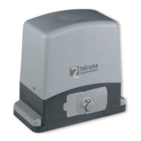
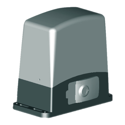
Telcoma Automations EVO ACE800 User manual

ACE500ET - ACE800
ISTEVO
V. 5.2007
Telcoma srl - Via L. Manzoni, 11 - Z.I. Campidui - 31015 Conegliano - (TV) Italy
Tel. +39 0438-451099 - Fax +39 0438-451102 - Part. IVA 00809520265
http://www.telcoma.it E-mail: info@telcoma .it
MOTORIDUTTORI ELETTROMECCANICI PER CANCELLI SCORREVOLI
MANUALE ISTRUZIONI E CATALOGO RICAMBI
I
OPÉRATEURS ÉLECTROMÉCANIQUES POUR PORTAILS COULISSANTS
NOTICE D'INSTRUCTIONS ET CATALOGUE DES PIÈCES DE RECHANGE
F
MOTORREDUCTORES ELECTROMECÁNICOS PARA CANCELAS CORREDERAS
MANUAL DE INSTRUCCIONES Y CATÁLOGO DE PIEZAS DE REPUESTO
E
ELECTROMECHANICAL GEARMOTORS FOR SLIDING GATES
INSTRUCTIONS MANUAL AND SPARE PARTS CATALOGUE
GB
ELEKTROMECHANISCHE SCHIEBETORANTRIEBE
BEDIENUNGSANLEITUNG UND ERSATZTEILKATALOG
D
ELEKTROMECHANISCHE REDUCTIEMOTOREN VOOR SCHUIFPOORTEN
GEBRUIKERSHANDLEIDING EN ONDERDELENCATALOGUS
NL
EVO

INFORMAZIONI GENERALI
I F E
2
I motoriduttori della serie EVO e ACE500ET -
ACE800E offrono un'ampia versatilità per
l'automazione di cancelli scorrevoli grazie alla
gamma di potenze, alle regolazioni di altezza e
profondità,aidispositividisicurezzainclusi.
Infatti, nei motori completi di centralina
elettronica, sono presenti dei sensori encoder
perlarilevazionedegliostacoli.
Per una sicura e corretta installazione vi
chiediamo, quindi, di leggere attentamente le
presenti istruzioni prestando particolare
attenzione al capitolo “AVVERTENZE
IMPORTANTI SULL'INSTALLAZIONE” e in
seguito di conservarle per una futura
consultazione.
Um EVO600 EVO600SC EVO800 EVO800SC EVO1200 EVO1200SC ACE800E
Vac 230 230 230 230 230 230 230
V 230Vac 230Vac 230Vac 230Vac 230Vac 230Vac 24Vdc
Kg 600 600 800 800 1200 1200 800
N 540 540 640 640 1200 1200 640
A 3,4 3,4 3,4 3,4 5,2 5,2 2,5
VA 800 800 800 800 1100 1100 500
μF 16 16 20 20 20 20 -
SI/YES - SI/YES - SI/YES - SI/YES
SI/YES - SI/YES - SI/YES - SI/YES
Nm 21 21 24 24 45 45 24
m/min 10 10 10 10 10 10 11
°C -20+70 -20+70 -20+70 -20+70 -20+70 -20+70 -20+70
°C 150 150 150 150 150 150 -
IP 43 43 43 43 43 43 43
%40 40 60 60 60 60 80
Kg 13 13 15 15 17 17 15
SI/YES - SI/YES - SI/YES - SI/YES
- SI/YES - SI/YES - SI/YES -
FF -
TS 10 TS 10 - - - - TS10
- - TS 20 TS 20 TS 40 TS 40 -
FF FF
DATI TECNICI
Tensione di alimentazione
Alimentazione motore
Peso max cancello
Forza di spinta
Corrente max assorbita
Potenza max assorbita
Condensatore
Classe di isolamento
Lubrificante grasso
Lubrificante olio
Coppia nominale
Velocità cancello
Temp. di funzionamento
Intervento termoprotezione
Grado di protezione
Encoder
Intermittenza lavoro
Peso
Finecorsa elettronico
Finecorsa meccanico
Centrale elettronica incorporata
INFORMATIONS GÉNÉRALES
Les opérateurs de la série EVO et
offrent une grande flexibilité pour
l'automatisation de portails coulissants grâce à
la gamme de puissances, aux réglages de
hauteur et profondeur, aux dispositifs de
sécuritéinclus.
En effet, les moteurs avec logique de
commande électronique sont équipés de
capteurs à encodeur pour la détection des
obstacles.
Pour une installation sûre et correcte, nous vous
prions donc de lire attentivement ces
instructionsen faisant particulièrement attention
au chapitre « RECOMMANDATIONS
IMPORTANTES POUR L'INSTALLATION » et
delesconserverpourtouteconsultationfuture.
ACE500ET -
ACE800E
INFORMACIONES GENERALES
Los motorreductores de la serie EVO y
ofrecen una amplia
versatilidad para la automatización de
cancelas correderas gracias a la gama de
potencias, a las regulaciones de altura y
profundidad y a los dispositivos de seguridad
incluidos.
En efecto, en los motores equipados con
central electrónica, se encuentran presentes
sensores codificadores para la detección de
losobstáculos.
Para llevar a cabo una instalación segura y
correcta le rogamos, por lo tanto, que lea
atentamente las presentes instrucciones
prestando una atención particular al capítulo
“ADVERTENCIAS IMPORTANTES SOBRE
LA INSTALACIÓN” y que las conserve para
unaconsultafutura.
ACE500ET - ACE800E
DONNÉES TECHNIQUES
Tension d'alimentation
Alimentation moteur
Poids max. portail
Force de poussée
Courant max. absorbé
Puissance max. absorbée
Condensateur
Logique électronique incorporée
Classe d'isolement
Lubrifiant graisse
Lubrifiant huile
Couple nominal
Vitesse portail
Température de fonctionnement
Intervention protection thermique
Indice de protection
Encodeur
Intermittence travail
Poids
Fin de course électronique
Fin de course mécanique
DATOS TÉCNICOS
Tensión de alimentación
Alimentación motor
Peso máx cancela
Fuerza de empuje
Corriente máx absorbida
Potencia máx absorbida
Condensator
Central electrónica incorporada
Clase de aislamiento
Lubrificante grasa
Lubrificante aceite
Par nominal
Velocidad cancela
Temp. de funcionamiento
Intervención termoprotección
Grado de protección
Encoder
Intermitencia trabajo
Peso
Fin de carrera electrónico
Fin de carrera mecánico
ACE500ET
230
24Vdc
500
500
2,6
600
-
18
11
-20+70
-
43
SI/YES
80
15
SI/YES
-
SI/YES
-
TS10
-

GB D NL
3
GENERAL INFORMATION
The EVO and series
gearmotors offer ample flexibility for the
automation of sliding gates thanks to the range
of powers, height and depth adjustment and
includedsafetydevices.
In fact, the motor with electronic control unit
includes encoder sensors for obstacle
detection.
Therefore, in order that the installation is
performed in a safe and correct manner, we
kindly ask you to carefully read the present
instructions giving particular attention to chapter
“IMPORTANT INSTALLATION WARNINGS"
and to keep these instructions in a safe place for
futurereference.
ACE500ET - ACE800E
ALLGEMEINE AUSKÜNFTE
Die Antriebe der Serien EVO und
bieten dank den verschiedenen
Leistungen, den Höhen- und Tiefenverstellungen
und den eingeschlossenen
Sicherheitsvorrichtungen eine große
Vielseitigkeit bei der Automatisierung von
Schiebetoren.
Die mit elektronischer Steuerung ausgestatteten
Antriebe verfügen über Encodersensoren zur
WahrnehmungderHindernisse.
Für eine sichere und korrekte Installation bitten
wir Sie daher, die vorliegenden Anweisungen
und insbesondere das Kapitel „WICHTIGE
HINWEISE ZUR INSTALLATION „ aufmerksam
zu lesen und sie dann für ein zukünftiges
Nachschlagenaufzubewahren.
ACE500ET -
ACE800E
ALGEMENE INFORMATIE
De reductiemotoren uit de serie EVO en
zijnuitermateveelzijdig
voor het automatiseren van schuifpoorten
dankzij een heel scala aan vermogen, afstelling
in hoogte en diepte, veiligheidsinrichtingen
inbegrepen.
In de motoren voorzien van een elektronische
besturingseenheid, bevinden zich
encodersensorenvoorobstakeldetectie.
Voor een veilige en correcte installatie
verzoeken wij u daarom deze aanwijzingen
aandachtig door te lezen en in het bijzonder het
hoofdstuk “BELANGRIJKE AANWIJZINGEN
VOOR HET INSTALLEREN” en ze daarna te
bewaren om ze in de toekomst te kunnen
raadplegen.
ACE500ET-ACE800E
TECHNICAL SPECIFICATIONS
Power Supply voltage
Motor power supply
Max. gate weight
Thrust force
Max. absorbed current
Max absorbed power
Capacitor
Incorporated electronic control unit
Insulation class
Grease lubricant
Oil lubricant
Nominal torque
Gate speed
Operating time
Thermal cut-out
Protection class
Encoder
Operating intervals
Weight
Electronic limit switch
Mechanical stop
TECHNISCHE DATEN
Spannungsversorgung
Motorversorgung
Höchstgewicht des Tors
Schubkraft
Max. Stromaufnahme
Max. Leistungsaufnahme
Kondensator
Eingebaute elektronische Steuerung
Isolationsklasse
Fettschmierung
Ölschmierung
Nenndrehmoment
Torgeschwindigkeit
Betriebstemp.
Auslösung des Wärmeschutzes
Schutzart
Encoder
Betriebsintermittenz
Gewicht
Elektronischer Endschalter
Mechanischer Endschalter
TECHNISCHE GEGEVENS
Spanning stroomvoorziening
Stroomvoorziening motor
Max gewicht poort
Duwkracht
Mas opgenomen stroom
Max opgenomen vermogen
Condensator
Ingebouwde besturingseenheid
Isoleringsklasse
Smeermiddel vet
Smeermiddel olie
Nominale koppel
Snelheid poort
Bedrijfstemp
Inwerkingtreding oververhittingsbeveiliging
Beschermingsklasse
Encoder
Onderbreking bedrijf
Gewicht
Elektronische eindschakelaar
Mechanische eindaanslag
Um EVO600 EVO600SC EVO800 EVO800SC EVO1200 EVO1200SC ACE800E
Vac 230 230 230 230 230 230 230
V 230Vac 230Vac 230Vac 230Vac 230Vac 230Vac 24Vdc
Kg 600 600 800 800 1200 1200 800
N 540 540 640 640 1200 1200 640
A 3,4 3,4 3,4 3,4 5,2 5,2 2,5
VA 800 800 800 800 1100 1100 500
μF 16 16 20 20 20 20 -
SI/YES - SI/YES - SI/YES - SI/YES
SI/YES - SI/YES - SI/YES - SI/YES
Nm 21 21 24 24 45 45 24
m/min 10 10 10 10 10 10 11
°C -20+70 -20+70 -20+70 -20+70 -20+70 -20+70 -20+70
°C 150 150 150 150 150 150 -
IP 43 43 43 43 43 43 43
%40 40 60 60 60 60 80
Kg 13 13 15 15 17 17 15
SI/YES - SI/YES - SI/YES - SI/YES
- SI/YES - SI/YES - SI/YES -
FF -
TS 10 TS 10 - - - - TS10
- - TS 20 TS 20 TS 40 TS 40 -
FF FF
ACE500ET
230
24Vdc
500
500
2,6
600
-
18
11
-20+70
-
43
SI/YES
80
15
SI/YES
-
SI/YES
-
TS10
-

4
QUADRO D'INSIEME
E
1.Supportoperlampeggiatore+antenna
2.Radiocomando
3.Lampeggiatore
4.Antenna
5.Selettore
6.Fotocellula
7.Cartellodiavvertenza
8.Bordoingomma
9.Lineadialimentazione
10.Interruttoregenerale
11. Interruttore differenziale
12.Magnetedifinecorsa
13.Cremagliera
14.Motoriduttore
15.Contropiastradifondazione(optional)
16.Piastradifissaggio
VUE D'ENSEMBLE
1.Supportpourclignotant+antenne
2.Radiocommande
3.Clignotant
4.Antenne
5.Sélecteur
6.Photocellule
7.Panneaudesignalisation
8.Bordencaoutchouc
9.Ligned'alimentation
10.Interrupteurgénéral
11. Interrupteur différentiel
12.Aimantde fin de course
13.Crémaillère
14.Opérateur
15.Contre-plaquedefondation(option)
16.Plaquedefixation
VISIÓN DE CONJUNTO
1.Soporteparaluzintermitente+antena
2.Radiocontrol
3.Luzintermitente
4.Antena
5.Selector
6.Fotocélula
7.Carteldeadvertencia
8.Bordedegoma
9.Líneadealimentación
10.Interruptorgeneral
11. Interruptor diferencial
12.Magnetodefindecarrera
13.Cremallera
14.Motorreductor
15.Contraplacadecimentación(facultativo)
16.Placadefijación
GB D NL
GENERAL LAYOUT
1.Aerial+ flashing light support
2.Remotecontrol
3.Flashinglight
4.Aerial
5.Selectorswitch
6.Photocell
7.Warningsign
8.Rubberedge
9.Powerline
10.Mainswitch
11. Differential switch
12.Limitswitchmagnet
13.Rack
14.Gearmotor
15.Foundationbaseplate(optional)
16.Fixingplate
GESAMTANSICHT
1.HalterungfürBlinkleuchte+Antenne
2.Funksteuerung
3.Blinkleuchte
4.Antenne
5.Schlüsseltaster
6.Fotozelle
7.Warnschild
8.Gummileiste
9.Versorgungslinie
10.Hauptschalter
11. Differentialschalter
12.Endschaltermagnet
13.Zahnstange
14.Getriebemotor
15.Fundamentgegenplatte(Optional)
16.Ankerplatte
OVERZICHTSTEKENING
1.Steunvoorknipperlicht+antenne
2.Afstandsbediening
3.Knipperlicht
4.Antenne
5.Keuzeschakelaar
6.Fotocel
7.Waarschuwingsbord
8.Rubberrand
9.Leidingstroomvoorziening
10.Hoofdschakelaar
11.Differentiaalschakelaar
12.Magneeteindschakelaar
13.Tandheugel
14.Reductiemotor
15.Contrafunderingsplaat(apartleverbaar)
16.Bevestigingsplaat
F
I

5
E
Prima di passare all' installazione si consiglia di
effettuarele seguenti verifiche e operazioni.
1. La struttura del cancello deve essere solida e
appropriata.
2. Durante la sua corsa, il cancello non deve
presentaresbandamentilaterali.
3. Il sistema ruote/rotaia inferiore e rulli/guida
superiore deve scorrere regolarmente senza
attriti.
4. Devono essere installate delle battute di
arresto meccanico del cancello scorrevole sia
inaperturacheinchiusura.
5. Nei cancelli preesistenti eliminare l'eventuale
serraturamanuale.
6. Portare alla base del cancello le canaline,
aventi un diametro, 25÷50 mm, necessarie
per il passaggio dei vari cavi elettrici quali
alimentazione di rete, fotocellula,
lampeggiatore,selettoreachiave,etc.
Avant de passer à l'installation, nous
conseillons d'effectuer les vérifications et
opérationsquisuivent.
1. La structure du portail doit être solide et
appropriée.
2. Durant sa course, le portail ne doit pas
présenterd'inclinaisonslatérales.
3.Le système roues/rail inférieur et
galets/glissière supérieure doit coulisser
régulièrementsansfrottements.
4. Des butées d'arrêt mécanique du portail
coulissant doivent être installées aussi bien
enouverturequ'enfermeture.
5. Dans les portails préexistants, éliminer
l'éventuelleserruremanuelle.
6.Amener jusqu'à la base du portail les gaines,
d'un diamètre de 25÷50 mm, nécessaires
pour le passage des différents câbles
électriques comme l'alimentation de
secteur, les photocellules, le clignotant, le
sélecteur a clé, etc.
Antes de pasar a la instalación le aconsejamos
que efectúe las siguientes verificaciones y
operaciones.
1. La estructura de la cancela tiene que ser
sólidayapropiada.
2. Durante su recorrido, la cancela no tiene
quepresentarinclinacioneslaterales.
3.El sistema ruedas/carril inferior y
rodillos/guía superior tiene que desplazarse
regularmentesinroces.
4. Tienen que instalarse topes de parada
mecánicos de la cancela corredera tanto en
laaperturacomoenelcierre.
5. En las cancelas preexistentes elimine la
eventualcerraduramanual.
6. Coloque en la base de la cancela los
canales, con un diámetro de 25÷50 mm,
que son necesarios para hacer pasar los
diversos cables eléctricos como el de
alimentación de red, el de la fotocélula, el
de la luz intermitente, el del selector con
llave, etc.
GB D NL
PRELIMINARY CONTROLS
The following controls and operations should
ideally be performed before commencing with
installation.
1. The gate structure must be solid and
appropriate.
2. The gate should have no lateral deviation
duringitsmovement.
3. The lower track/wheel and upper guide/wheel
systemmustslideevenlywithoutfriction.
4. The sliding gate mechanical stops must be
installedbothinopeningaswellasinclosing.
5. Remove the manual lock of already existing
gates.
6. A channel with a diameter of 25÷50 mm must
be taken to the base of the gate in order to
pass the cables for the mains power supply,
photocell, flashing light, key operated selector
switch,etc.
ÜBERPRÜFUNGEN UND VORBEREITUNGEN
Bevor man auf die Installation übergeht, sollten
folgende Überprüfungen und Vorgänge
ausgeführtwerden:
1. Die Torstruktur muss solide und geeignet
sein.
2. Das Tor darf während seines Laufs seitlich
nichtentgleisen.
3. Die Räder auf der unteren Schiene und die
Rollen in der oberen Führung müssen
regelmäßigundohneReibungengleiten.
4. Das Schiebetor muss über mechanische
AnschlägesowohlinderÖffnung
alsauchinder Schließungverfügen.
5. An bereits vorhandenen Toren muss das
eventuelle manuelle Schloss entfernt
werden.
6. Die Kanäle mit einem Durchmesser von
25÷50 mm zum Durchführen der
verschiedenen elektrischen Kabel
(Netzstromversorgung, Fotozelle,
Blinkleuchte, Schlüsseltaster, usw.) bis zur
BasisdesTors führen.
CONTROLES VOORAF
Voordat u tot installatie over gaat is het
raadzaam onderstaande controles en
handelingenuittevoeren.
1. De poort moet een stevige en adequate
structuurhebben.
2. Tijdens zijn loop mag de poort niet zijdelings
uithetgeleidingssysteemkomen.
3. Het systeem wielen/rails aan de onderzijde
en rollen/geleiding aan de bovenzijde moet
regelmatigverschuivenzonderwrijvingen.
4. Er dienen mechanische stops bij de
schuifpoort zowel aan de openings- als
sluitzijdeaangebrachtteworden.
5. Bij reeds bestaande poorten dient u een
eventueel slot met handbediening weg te
halen.
6. Breng aan de onderzijde van de poort de
kabelgootjes met een doorsnede van,
25÷50 mm, waardoor de verschillende
elektriciteitskabels zoals stroomtoevoer van
het net, fotocel, knipperlicht,
sleutelschakelaar, etc. moeten lopen.
F
I
VERIFICHE PRELIMINARI CONTRÔLES PRÉLIMINAIRES VERIFICACIONES PRELIMINARES

6
E
1. Eseguire uno scavo di fondazione, tenendo
conto delle misure della piastra di fondazione
(Fig.2).
2. Alloggiare nello scavo le canaline (diam. mm
25÷50) per il passaggio dei cavi di
alimentazioneedicollegamentoesterno.
3. Annegare nel calcestruzzo le canaline e la
piastra di fondazione dopo averne controllato,
con l'ausilio di una livella, le quote e
l'orizzontalità. Rispettare misure e angoli
indicati in Fig. 3a (installazione destra) e in
Fig. 3b (installazione sinistra) rappresentano
il minimo indispensabile per un perfetto
accoppiamentotrapignoneecremagliera.
Eventuali piccole imprecisioni di
posizionamento in altezza e profondità della
piastra di fondazione possono comunque
essere corrette agendo successivamente sul
sistemadiregolazionedelmotoriduttore.
Fissare il motore sulla piastra solo quando il
calcestruzzo sarà perfettamente solidificato e
asciugato.
Prestare molta attenzione al verso di
montaggio. I fori per il passaggio delle
canalinedevonotrovarsiasinistra(fig.2).
Prestare molta attenzione alle quote indicate
nellafigura4.
1.Creuser un trou, en tenant compte des
dimensionsdelaplaquedefondation(Fig.2).
2. Loger dans le trou les gaines (diam. mm
25÷50) pour le passage des câbles
d'alimentationetdeconnexionextérieure.
3. Noyer dans le béton les gaines et la plaque de
fondation après en avoir contrôlé, avec un
niveau, les distances et l'horizontalité.
Respecter les mesures et les angles indiqués
dans la Fig. 3a (installation droite) et dans la
Fig.3b(installationgauche).
Elles représentent le minimum indispensable
pour un accouplement parfait entre pignon et
crémaillère.
Les éventuelles petites imprécisions de
positionnement en hauteur et profondeur de la
plaque de fondation peuvent être corrigées
dans tous les cas en agissant successivement
surlesystèmederéglagedel'opérateur.
Fixer le moteur sur la plaque uniquement quand
lebétonseracomplètementsolidifiéetsec.
Faire très attention au sens de montage. Les
trous pour le passage des gaines doivent se
trouveràgauche(fig.2).
Faire très attention aux mesures indiquées
danslafigure4.
1. Efectúe una excavación de cimentación,
teniendo en cuenta las medidas de la placa
decimentación(Fig.2).
2. Coloque los canales en la excavación
(diám. mm 25÷50) para hacer pasar los
cables de alimentación y de conexión
externa.
3. Cubra con hormigón los canales y la placa
de cimentación después de haber
controlado, con la ayuda de un nivel, las
cotas y la horizontalidad. Respete las
medidas y los ángulos que se indican en la
Fig. 3a (instalación derecha) y en la Fig. 3b
(instalaciónizquierda).
Representan el mínimo indispensable para
obtener un acoplamiento perfecto entre
piñónycremallera.
Eventuales pequeñas imprecisiones de
emplazamiento en altura y profundidad de la
placa de cimentación se pueden corregir de
todas formas accionando sucesivamente el
sistemaderegulacióndelmotorreductor.
Fije el motor sobre la placa sólo cuando el
hormigón se haya solidificado y secado
perfectamente.
Preste mucha atención al sentido del
montaje. Los orificios para el paso de los
canales tienen que encontrarse a la
izquierda(fig.2).
Preste mucha atención a las cotas
indicadasenlafigura4.
F
I
INSTALLAZIONE SU PIASTRA DI
FONDAZIONE (OPZIONALE)
INSTALLATION SUR PLAQUE DE
FONDATION (OPTION)
INSTALACIÓN SOBRE PLACA DE
CIMENTACIÓN (OPCIONAL)
Fig. 2 - Abb. 2
Fig. 3a - Abb. 3a Fig. 3b - Abb. 3b
Fig. 4 - Abb. 4

7
GB D NL
1.Dig a foundation hole, taking into
consideration the dimensions of the
foundationplate(Fig.2).
2. Place the channel (dia. 25÷50 mm) for the
power supply cable and external connections
inthehole.
3. Submerge the channels and foundation plate
into the concrete previously having checked
the heights and level with a spirit level.
Comply with the measurements and angles
indicated in Fig. 3a (righthand installation)
and in Fig. 3b (lefthand installation) that
represent the minimum necessary for a
perfect coupling between the rack and the
pinion.
Possible positioning imperfections in the height
and depth of the foundation plate can be
subsequently corrected through the adjustment
systemofthegearmotor.
Fix the gearmotor on the plate only when the
concrete has perfectly hardened and is
completelydry.
Take particular care of the assembly
direction. The holes for the passage of the
channelmustbeontheleft(fig.2).
Pay particular attention to the heights
indicatedinFig4.
1. Unter Berücksichtigung der Abmessungen
der Fundamentplatte (Abb. 2) ein Fundament
ausgraben.
2. In der Ausgrabung die Kanäle (Durchm. mm
25÷50) zum Durchführen der Versorgungskabel
und der externen Verbindungskabel
unterbringen.
3. Die Maße und die Waagerechte der Kanäle
und der Fundamentplatte mit einer
Wasserwaage kontrollieren, dann diese im
Beton versenken. Die inf den Abb. 3a
(Installation rechts) und 3b (Installation links)
angegebenenMaßebeachten.<0}
Sie sind die für eine einwandfreie Kopplung
zwischen Ritzel und Zahnstange unbedingt
notwendigenMindestmaße.
Kleine Ungenauigkeiten beim Positionieren der
Fundamentplatte in Höhe und Tiefe können
auch später mit dem Einstellsystem des
Antriebsberichtigtwerden.
DenAntrieb erst auf der Platte befestigen, wenn
derBetonganzfestundtrockenist.
Den Montagesinn genau beachten. Die
Löcher zum Durchführen der Kanäle
müssensichlinksbefinden(Abb.2).
Die in Abbildung 4 angegebenen Maße
genauestenseinhalten.
1. Maak een funderingspunt en houd daarbij
rekening met de afmetingen van de
funderingsplaat(afb.2).
2. Breng de kabelgootjes (diam. mm 25÷50)
voor de kabels voor stroomvoorziening en
externeaansluitingindefunderingsputaan.
3. Leg de kabelgootjes en de funderingsplaat
in het beton nadat u met behulp van een
waterpas de waarden en het feit of alles
horizontaal is, gecontroleerd hebt. Neem de
afmetingen en hoeken in acht zoals die op
afb. 3a (installatie rechts) en op afb. 3b
(installatie links) aangegeven zijn; zij zijn het
absolute minimum dat noodzakelijk is voor
een perfecte koppeling tussen rondsel en
tandheugel.
Eventuele kleine onnauwkeurigheden in
hoogte en diepte bij het plaatsen van de
funderingsplaat kunnen echter verholpen
worden door later het afstelsysteem van de
reductiemotortegebruiken.
Bevestig de motor pas op de plaat wanneer het
betonvolkomendroogenhardis.
Let heel goed op de richting van montage.
De boringen waar de kabelgootjes
doorheen moeten lopen, moeten zich links
bevinden(afb.2).
Let goed op de op afbeelding 4 aangegeven
waarden.
INSTALLATION ON THE FOUNDATION
PLATE (OPTIONAL)
NSTALLATION AUF FUNDAMENTPLATTE
(OPTIONAL)
INSTALLATIE OP FUNDERINGSPLAAT
(APART LEVERBAAR)
Fig. 2 - Abb. 2
Fig. 3a - Abb. 3a Fig. 3b - Abb. 3b
Fig. 4 - Abb. 4

8
INSTALLAZIONE SU PIASTRA IN
DOTAZIONE
E
Se il cancello è provvisto di solido basamento in
cemento, il motoriduttore può essere ancorato
direttamente al suolo usando la piastra di
fissaggio (fornita assieme al motoriduttore) con
quattrorobustitasselliadespansione(fig.5).
Eventuali piccole imprecisioni di
posizionamento in altezza e profondità della
piastra di fissaggio possono comunque essere
corretteagendosuccessivamente sul sistema di
regolazionedelmotoriduttore.
Prestare molta attenzione alle quote indicate
nellafigura4.
INSTALLATION SUR PLAQUE FOURNIE
Si le portail est muni d'une solide base en
ciment, l'opérateur peut être fixé directement
sur le sol en utilisant la plaque de fixation
(fournie avec l'opérateur) avec quatre grosses
chevillesàexpansion(fig.5).
Les éventuelles petites imprécisions de
positionnement en hauteur et profondeur de la
plaque de fixation peuvent être corrigées dans
tous les cas en agissant successivement sur le
systèmederéglagedel'opérateur.
Faire très attention aux mesures indiquées
danslafigure4.
INSTALACIÓN SOBRE PLACA
SOMINISTRADA
Si la cancela dispone de una bancada de
cemento sólida, el motorreductor se puede fijar
directamente en el suelo utilizando la placa de
fijación (que se suministra junto con el
motorreductor) con cuatro tacos de expansión
robustos(fig.5).
Eventuales pequeñas imprecisiones de
emplazamiento en altura y profundidad de la
placa de fijación se pueden corregir de todas
formas accionando sucesivamente el sistema
deregulacióndelmotorreductor.
Preste mucha atención a las cotas indicadas
enlafigura4.
GB D NL
INSTALLATION ON THE SUPPLIED
PLATE
If the gate already has a solid concrete base,
then the gearmotor can be fixed directly to the
ground using the fixing plate (supplied along
with the gearmotor) with four sturdy expansion
bolts(fig.5).
Possible positioning imperfections in the
height and depth of the foundation plate can be
subsequently corrected through the
adjustmentsystemofthegearmotor.
Pay particular attention to the heights
indicatedinFig4.
INSTALLATION AUF MITGELIEFERTER
PLATTE
Falls das Tor mit einem soliden
Zementfundament versehen ist, kann der
Antrieb mit Hilfe der Ankerplatte (mitgeliefert)
und vier robusten Spreizdübeln (Abb. 5) direkt
mitdemBodenverankertwerden.
Kleine Ungenauigkeiten beim Positionieren der
Ankerplatte in Höhe und Tiefe können auch
später mit dem Einstellsystem des Antriebs
berichtigtwerden.
Die in Abbildung 4 angegebenen Maße
genauestenseinhalten.
INSTALLATIE OP MEEGELEVERDE
PLAAT
Als de poort voorzien is van een stevige
grondplaat van cement, kan de reductiemotor
rechtstreeks op de bodem verankerd worden
waarbij u de bevestigingsplaat gebruikt
(meegeleverd met de reductiemotor) met vier
sterkeexpansiepluggen(afb.5).
Eventuele kleine onnauwkeurigheden in
hoogte en diepte bij het plaatsen van de
funderingsplaat kunnen echter verholpen
worden door later het afstelsysteem van de
reductiemotortegebruiken.
Let goed op de op afbeelding 4 aangegeven
waarden.
F
I
Fig. 5 - Abb. 5
Fig. 4 - Abb. 4

9
SBLOCCAGGIO DEL MOTORIDUTTORE
E
Per sbloccare il motoriduttore inserire e girare la
chiave, tirare poi la leva dello sportellino come
indicatoinfig.6e7
DÉBLOCAGE DE L'OPÉRATEUR
Pour débrayer l'opérateur, introduire et tourner
la clé, tirer ensuite le levier de la porte comme
l'indiquelafig.6et7.
DESBLOQUEO DEL MOTORREDUCTOR
Para desbloquear el motorreductor introduzca y
gire la llave, tire luego la palanca de la puerta tal
comoseindicaenlasfig.6y7.
GB D NL
GEARMOTOR RELEASE
In order to release the gearmotor, insert and
turn the key, then pull the lever of the cover flap
asindicatedinfigures6and7.
ENTRIEGELN DES ANTRIEBS
Zum Entriegeln des Antriebs, den Schlüssel
einstecken und drehen, dann den Hebel an der
Lukedrehen,wieindenAbb.6 und 7 gezeigt.
ONTGRENDELING VAN DE
REDUCTIEMOTOR
Voor het ontgrendelen van de reductiemotor
dient u de sleutel in het slot te steken en die om
te draaien, vervolgens aan de hendel van het
luikje te trekken zoals dat op afb. 6 en 7 is
aangegeven.
F
I
Fig. 7 - Abb. 7
Fig. 6 - Abb. 6

10
E
Portareilcancelloincompletaapertura.
Sistemare il motoriduttore sulla piastra fissata in
precedenza mediante le apposite viti in
dotazione.
Regolare i grani di regolazione in altezza (vedi
particolare B di fig. 10) in modo che il
motoriduttore si alzi di circa 4mm dalla piastra di
fissaggio.
Appoggiare un elemento di cremagliera al
pignone, e fissare lo stesso con viti e distanziali
alcancello.
Spostare manualmente il cancello portando il
pignone in corrispondenza dell'ultimo
distanziale.
Fissare l'elemento di cremagliera
definitivamente.
Per un corretto posizionamento degli altri
elementi e garantire la loro rettilineità, è
necessario utilizzare un elemento di
cremagliera usandolo come appoggio e
riferimento(Fig.8).
Si deve garantire un'aria fra cremagliera e
pignone di 2 mm così da non far gravare il peso
del cancello sul pignone del motoriduttore (vedi
fig 9). Per far questo agire nei grani di
regolazionedelmotoriduttore(part.Bdifig.10).
Nel caso di cancelli nuovi verificare in tempi
successivi all'installazione il gioco fra
cremagliera e pignone, se necessario agire nei
grani di regolazione oppure sulle asole della
cremaglieraperregistrareigiochi
N.B.
Mettreleportailenouverturecomplète.
Placer l'opérateur sur la plaque précédemment
fixéeaveclesvisfournies.
Régler les goujons de réglage en hauteur (voir
détail B - fig. 10) de manière que l'opérateur soit
soulevé d'environ 4 mm par rapport à la plaque
defixation.
Appuyer un élément de crémaillère sur le
pignon, et le fixer avec des vis et des entretoises
auportail.
Déplacer manuellement le portail en mettant le
pignonauniveaudeladernièreentretoise.
Fixerdéfinitivementl'élémentdecrémaillère.
Pour un positionnement correct des autres
éléments et pour qu'ils soient bien rectilignes, il
faututiliser un élément de crémaillère qui servira
d'appuietderepère(Fig.8).
Il faut garantir un espace de 2 mm entre la
crémaillère et le pignon de manière que le poids
du portail ne porte pas sur le pignon de
l'opérateur (voir fig. 9). Pour cela, agir sur les
goujons de réglage de l'opérateur (détail B - fig.
10).
Dans le cas de portails neufs, vérifier après
l'installation le jeu entre la crémaillère et le
pignon, si nécessaire agir sur les goujons de
réglage ou sur les fentes de la crémaillère pour
réglerlesjeux.
N.B.
Coloque la cancela en posición de apertura
completa.
Sitúe el motorreductor sobre la placa fijada
anteriormente mediante los tornillos
correspondientessuministrados.
Regule los bulones de centraje de regulación en
altura(véase detalle Bdela fig.10)de forma que
elmotorreductorselevante aproximadamente 4
mmde laplacade fijación.
Apoye un elemento de cremallera al piñón y
fíjelocon tornillosydistanciadores alacancela.
Desplace manualmente la cancela situando el
piñón en el punto que coincide con el último
distanciador.
Fijeel elementodecremallera definitivamente.
Para conseguir un emplazamiento correcto de
losdemáselementosygarantizarsurectitud,es
necesario utilizar un elemento de cremallera
usándolo como punto de apoyo y de referencia
(Fig.8).
Se tiene que garantizar un espacio entre la
cremallera y el piñón de 2 mm para evitar que el
peso de la cancela no descanse sobre el piñón
del motorreductor (véase fig 9). Para ello
accione los bulones de centraje de regulación
delmotorreductor (part.Bde lafig.10).
Cuando se trata de cancelas nuevas,
compruebe sucesivamente a la instalación el
juego entre la cremallera y el piñón, en caso
necesario accione los bulones de centraje de
regulación o las ranuras de la cremallera para
reglarlos juegos.
N.B.
F
I
Fig. 8 - Abb. 8 Fig. 9 - Abb. 9
MONTAGGIO CREMAGLIERA MONTAGE CRÉMAILLÈRE MONTAJE DE LA CREMALLERA

11
NL
Openthegatefully.
Place the gearmotor on the plate that was
previouslysecuredwiththesuppliedscrews.
Regulate the height adjustment dowels (see
detail B in Fig. 10) so that the gearmotor lifts
fromtheplatebyabout4mm.
Place a rack element on the pinion and fix it to
thegatewithscrewsandspacers.
Manually move the gate and position the pinion
incorrespondencewiththelastspacer.
Permanentlyfixtherack.
In order to correctly position the other parts and
guarantee their alignment, a rack section must
beusedasasupportandreference(Fig.8).
A 2 mm gap must be maintained between the
rack and the pinion so as not to overload the
weight of the gate on the pinion of the gearmotor
(see fig. 9). This is done through the regulation
of the gearmotor's adjustment dowels (detail B
offig.10).
After the installation of new gates, every so
often, check the play between the rack and the
pinion; if necessary adjust the play by means of
the adjustment dowels or by means of the slots
oftherack.
N.B.
DasTor ganz öffnen.
Den Antrieb auf der vorher mit den
mitgelieferten Schrauben befestigten Platte
anbringen.
Die Verstellstifte in der Höhe regulieren (siehe
Detail B in Abb. 10), so dass sich derAntrieb ca.
4mmvonderAnkerplattehebt.
Ein Zahnstangenelement auf das Ritzel legen
und dieses mit Schrauben und Distanzstücken
amTor befestigen.
Das Tor von Hand verschieben, bis sich das
RitzelamletztenDistanzstückbefindet.
DasZahnstangenelementendgültigbefestigen.
Um die anderen Elemente korrekt anzubringen
und ihre Geradlinigkeit zu gewährleisten, muss
ein Zahnstangenelement als Stütze und
Bezugnahmebenutztwerden(Abb.8).
Zwischen Zahnstange und Ritzel muss ein
Spiel von 2 mm garantiert sein, damit das
Torgewicht nicht auf dem Ritzel des Antriebs
lastet (siehe Abb. 9). Hierzu sind die
Verstellstifte des Antriebs zu betätigen (Detail B
inAbb.10).
Im Fall neuer Tore muss das Spiel zwischen
Zahnstange und Ritzel nach der Installation
kontrolliert werden; ggf. die Verstellstifte oder
die Schlitze der Zahnstange betätigen, um das
Spielzuregulieren.
N.B.
Zetdepoorthelemaalopen.
Breng de reductiemotor met behulp van de
speciale meegeleverde schroeven op de
reedseerderbevestigdeplaataan.
Stel de stelstiften zodanig in de hoogte (zie
detail B op afb. 10) af dat de reductiemotor
ongeveer circa 4mm boven de
bevestigingsplaatkomttestaan.
Laat een element van de tandheugel op het
rondsel rusten en bevestig dit met schroeven
enafstandsstukkenopdepoort.
Verplaats de poort handmatig en breng het
rondselbijhetlaatsteafstandsstuk.
Bevestighettandheugelelementdefinitief.
Voor een correcte positionering van de andere
elementen en garanderen dat ze op één rechte
lijn liggen, dient u een tandheugelelement als
steunenreferentietegebruiken(afb.8).
U dient een ruimte tussen de tandheugel en
het rondsel van 2 mm aan te houden zodat het
gewicht van de poort niet op het rondsel van de
reductiemotor komt te rusten (zie afb. 9).
Hiervoor gebruikt u de stelstiften van de
reductiemotor(deelBopafb.10).
In het geval van nieuwe poorten dient u na
verloop van tijd na installatie de speling tussen
tandheugel en rondsel te controleren; gebruik
zo nodig de stelstiften of de schuifopeningen
van de tandheugel om de spelingen af te
stellen.
N.B.
D
GB
RACK ASSEMBLY MONTAGE DER ZAHNSTANGE MONTAGE TANDHEUGEL
Fig. 10 - Abb. 10

12
E
Appoggiare il motoriduttore sulla piastra
precedentemente fissata al basamento,
avvitare le 4 vitiAvedi fig 10. Prima di avvitare a
fondo le 4 vitiA, è possibile regolare la distanza
del motore dalla cremagliera agendo nei grani
B indicati sempre in fig. 10. In seguito è
importante bloccare energicamente le 4 viti A.
assicurandosi che durante tutta la corsa del
cancello,ilmotoriduttoresiabensaldoaterra.
Poser l'opérateur sur la plaque précédemment
fixée à la base, visser les 4 vis A (voir fig. 10).
Avant de visser à fond les 4 visA, il est possible
de régler la distance du moteur par rapport à la
crémaillère en agissant sur les goujons B
indiqués eux aussi dans la fig. 10. Ensuite, il est
importer de serrer à fond les 4 vis A, en
contrôlant que durant toute la course du portail,
l'opérateurestbienfixéausol.
Apoye el motorreductor sobre la placa
precedentemente fijada a la bancada, atornille
los 4 tornillos A (véase la fig 10). Antes de
atornillar a fondo los 4 tornillos A, es posible
regular la distancia del motor de la cremallera
accionandolosbulonesde centraje B indicados
siempre en la fig. 10. A continuación es
importante bloquear enérgicamente los 4
tornillosAasegurándose de que durante todo el
recorrido de la cancela el motorreductor se
encuentrebiensujetoalsuelo.
GB D NL
Place the gearmotor onto the plate that was
previously fixed to the base and tighten the 4
bolts A (see fig. 10). The distance of the
gearmotor from the rack can be adjusted by
means of the dowels B illustrated in Fig. 10,
before fully tightening the four boltsA.After this
has been done, the 4 bolts A must be fully
tightened, making sure that the gearmotor is
firmly secured to the ground while the gate is in
motion.
Den Antrieb auf der vorher am Fundament
befestigten Platte mit den 4 Schrauben A
befestigen – siehe Abb. 10. Bevor die 4
Schrauben A festgezogen werden, kann der
Abstand zwischen Antrieb und Zahnstange
durch Betätigung der Stifte, angegeben in Abb.
10, reguliert werden. Wichtig: die 4 SchraubenA
danach energisch festziehen und sicherstellen,
dass der Antrieb während des Torlaufs fest mit
demBodenverankertbleibt.
Zet de reductiemotor op de plaat die u
daarvoor op de grondplaat hebt bevestigd,
draai de 4 schroeven A van afb. 10 aan.
Voordat u de 4 schroeven A helemaal vast
draait, is het mogelijk de afstand van de motor
ten opzichte van de tandheugel af te stellen,
waarvoor u de stiften B op afb. 10. gebruikt.
Vervolgens is het van belang de 4 schroevenA
stevig vast te draaien waarbij u zich ervan
dient te vergewissen dat de reductiemotor
over de gehele loop van de poort goed vast zit
opdegrond.ne.
F
I
Fig. 10 - Abb. 10
FIXING OF THE GEARMOTOR BEFESTIGUNG DES ANTRIEBS BEVESTIGING VAN DE REDUCTIEMOTOR
FISSAGGIO DEL MOTORIDUTTORE FIXATION DE L'OPÉRATEUR FIJACIÓN DEL MOTORREDUCTOR

13
E
Nelle versioni con centralina incorporata, i
motoriduttori sono dotati di finecorsa elettronici
(FCEVO) mentre le versioni senza centralina
elettronica montano dei finecorsa meccanici
(FCM).
- Nel FCEVO fare attenzione che ciascuna
staffa con i magneti sia sufficientemente
vicina a finecorsa elettronico in modo da
garantire lo stop del motore.
(alimentazione24V)
(negativoecomunefinecorsa)
(contattifinecorsa)
- Nel Finecorsa meccanico FCM verificare che
la corsa della molla sulla staffa avvenga
correttamente senza impedimenti. Per piccoli
aggiustamenti intervenire sulla staffa. (vedi fig.
12)
La distanza da
tenere tra magnete ed FCEVO deve essere
compresafrai5ei10mm.(vedi fig 11)
CollegamentiFCEVO
Giallo
Marrone
Verde/Bianco
Dans les versions avec logique de commande
incorporée, les opérateurs sont munis de fins de
course électroniques (FCEVO) tandis que les
versions sans logique de commande ont des
finsdecoursemécaniques(FCM).
- Dans le FCEVO, faire attention que chaque
patte de support des aimants se trouve
suffisamment près du fin de course
électronique de manière à garantir l'arrêt du
moteur.
(alimentation24V)
(négatifetcommunfindecourse)
(contactsfindecourse)
- Dans le fin de course mécanique FCM vérifier
que la course du ressort sur la patte s'effectue
correctement sans obstacles. Pour les petites
mises au point, intervenir sur la patte. (voir fig.
12)
La distance à maintenir entre
l'aimant et le FCEVO doit être comprise
entre5et10mm.(voirfig.11)
ConnexionsFCEVO
Jaune
Marron
Vert/Blanc
En las versiones con centralina incorporada, los
motorreductores están equipados con fines
de carrera electrónicos (FCEVO) mientras las
versiones sin central electrónica montan fines
decarreramecánicos(FCM).
- En el FCEVO controle que cada una de las
abrazaderas con los magnetos se encuentre
suficientemente cercana al fin de carrera
electrónico de forma que garantice el freno
del motor.
(alimentación24V)
(negativoycomúndelfindecarrera)
(contactosdelfindecarrera)
- En el fin de carrera mecánico FCM
compruebe que el recorrido del muelle sobre
la abrazadera se lleve a cabo correctamente
sin obstáculos. Para pequeños ajustes
accionelaabrazadera.(véasefig.12)
La distancia que es necesario
mantener entre el magneto y el FCEVO
tiene que estar comprendida entre los 5 y
los10mm.(véasefig.11)
ConexionesFCEVO
Amarillo
Marrón
Verde/Blanco
F
I
Fig. 11 - Abb. 11 Fig. 12 - Abb. 12
FINECORSA FIN DE COURSE FIN DE CARRERA

14
NL
For versions with incorporated control unit, the
gearmotors are equipped with electronic limit
switches (FCEVO) while versions without the
electronic control unit are fitted with mechanical
stops(FCM).
- Make sure that on the FCEVO version, each
bracket with magnets is sufficiently close to
the electronic limit switch in order to
guarantee that the motor stops.
(power24V)
(limitswitchcommonandnegative)
(limitswitchcontacts)
- For mechanical stops (FCM), make sure that
the travel of the spring on the bracket occurs
without difficulty. Adjust the bracket for slight
corrections(seefig.12).
The distance
between the magnets and the FCEVO
mustbebetween5and10mm(seefig.11).
FCEVOconnections
Yellow
Brown
Green/White
Die Ausführungen mit eingebauter Steuerung
verfügen über elektronische Endschalter
(FCEVO), wogegen jene ohne elektronische
Steuerung mit mechanischen Endschaltern
(FCM)ausgestattetsind.
- Am FCEVO ist zu beachten, dass jeder Bügel
mit den Magneten ausreichend nah am
elektronischen Endschalter angebracht ist, um
das Anhalten des Antriebs zu garantieren.
(24VVersorgung)
(Minus und gemeinsamer Leiter des
Endschalters)
(Endschalterkontakte)
- Am mechanischen Endschalter FCM prüfen,
dass sich die Feder am Bügel korrekt und
hindernisfrei bewegt. Kleine Justierungen
können am Bügel ausgeführt werden (siehe
Abb.12)
Der
Abstand zwischen Magnet und FCEVO
muss zwischen 5 und 10 mm sein (siehe
Abb.11)
ANSCHLÜSSEDESFCEVO
gelb
braun
grün/weiß
In de uitvoeringen met funderingsplaat zijn de
reductiemotoren met elektronische
eindschakelaars (FCEVO) toegerust, terwijl
op de uitvoeringen zonder elektronische
besturingseenheid mechanische
eindaanslagen(FCM)wordengemonteerd.
- Bij de FCEVO dient u erop te letten dat elke
beugel met de magneten zich dicht genoeg
bij de elektronische eindschakelaar bevindt
om het stoppen van de motor te waarborgen.
(stroomvoorziening24V)
(min en gemeenschappelijk
eindschakelaar)
(contacteneindschakelaar)
- Bij de mechanische eindaanslag FCM dient u
te controleren dat de veer correct zonder
belemmeringen op de beugel kan lopen.
Kleine correcties voert u op de beugel uit. (zie
afb.12)
De afstand die moet worden
aangehouden tussen magneet en FCEVO
moet tussen de 5 en 10 mm liggen. (zie
afb.11)
AansluitingenFCEVO
Geel
Bruin
Groen/Wit
D
GB
Fig. 11 - Abb. 11 Fig. 12 - Abb. 12
LIMIT SWITCH AND STOP ENDSCHALTER EINDSCHAKELAARS

15
E
Collegare un cavo di sezione almeno 3x1.5mmq
per l'alimentazione 230Vac nella morsettiera
indicata dalla figura 13. (
)
Per i motoriduttori con centralina elettronica
incorporata, alcuni cablaggi sono già effettuati.
Completare i cablaggi rimanenti seguendo le
istruzionidellacentralina.
Per i motoriduttori senza centralina seguire i
collegamentidilafigura14
Per alimentare il motore collegare un cavo di
sezione 4 x 1,5 mmq, dalla centralina elettronica
di comando alla morsettiera interna al
motoriduttore. Il condensatore deve essere
collegatoparalleloaiduefilidifase.
Per i finecorsa collegare un cavo di sezione 3 x
0,5 mmq., dalla centralina elettronica alla
morsettierainternaalmotoriduttore.
ACE500ET -
ACE800E
Connecter un câble ayant une section minimum
de 3 x 1,5 mm² pour l'alimentation 230 Vca dans
le bornier indiqué sur la figure 13.
Pour les opérateurs avec logique de commande
électronique incorporée, certains câblages sont
déjà effectués. Compléter les câblages restants
en suivant les instructions de la logique de
commandeproprementdite.
Pour les opérateurs sans logique de
commande, suivre les indications de connexion
delafigure14
Pour alimenter le moteur, connecter un câble
d'une section de 4 x 1,5 mm², de la logique de
commande électronique au bornier interne de
l'opérateur. Le condensateur doit être connecté
enparallèleauxdeuxfilsdephase.
Pour les fins de course, connecter un câble
d'une section de 3 x 0,5 mm², de la logique de
commande électronique au bornier interne de
l'opérateur.
(ACE500ET -
ACE800E)
Conecte un cable de sección de por lo menos 3
x 1.5 mm2 para la alimentación 230Vac en la
regleta de conexiones indicada por la figura 13.
Para los motorreductores con central
electrónica incorporada, algunos cableados ya
están efectuados. Complete los cableados
restantes siguiendo las instrucciones de la
central.
Para los motorreductores sin central siga las
conexionesdelafigura14.
Para alimentar el motor, conecte un cable de
sección4x 1,5 mm2 desde la central electrónica
de control a la regleta de conexiones interna del
motorreductor. El condensador tiene que estar
conectado en paralelo a los dos hilos de fase.
Para los fines de carrera, conecte un cable de
sección3x 0,5 mm2 desde la central electrónica
a la regleta de conexiones internoa del
motorreductor.
(ACE500ET-ACE800E)
F
I
Fig. 13 - Abb. 13 Fig. 14 - Abb. 14
COLLEGAMENTI ELETTRICI BRANCHEMENTS ÉLECTRIQUES CONEXIONES ELÉCTRICAS
ACE500ET - ACE800E EVO...SC

16
NL
Connect a cable for the 230 Vac power supply
with a section of at least 3x1.5 mm2, to the
terminal block illustrated in fig. 13.
Some of the wiring is already made on the
gearmotors with incorporated electronic control
unit. Complete the remaining wiring following
theinstructionofthecontrolunit.
Follow the instructions in fig. 14 for gearmotors
withoutcontrolunit.
To power the gearmotor, connect a 4 x 1.5 mm2
section cable from the electronic control unit to
the terminal block inside the gearmotor. The
condenser must be connected in parallel with
thetwophasewires.
For the limit switch, connect a 3 x 0.5 mm2 cable
from the electronic control unit to the terminal
blockinsidethegearmotor.
(ACE500ET -
ACE800E)
Für die 230Vac Versorgung ein Kabel mit einem
Querschnitt von mindestens 3x1.5mm2 an der
in Abbildung 13 (ACE500ET - ACE800E)
gezeigtenKlemmleisteanschließen.
An den Antrieben mit eingebauter
elektronischer Steuerung sind einige
Verdrahtungen bereits ausgeführt. Die
restlichen Verdrahtungen nach den
AnweisungenderSteuerungvervollständigen.
Für die Antriebe ohne Steuerung sind die
AnschlüsseinAbbildung14 auszuführen.
Um den Antrieb zu speisen, ein Kabel mit einem
Querschnitt von 4 x 1,5 mm2 von der
elektronischen Steuerung an der Klemmleiste im
Antrieb anschließen. Der Kondensator muss mit
denbeiden Phasenleiternparallelgeschaltetsein.
Für die Endschalter, ein Kabel mit einem
Querschnitt von 3 x 0,5 mm2 von der
elektronischen Steuerung an der Klemmleiste
imAntriebanschließen.
Sluit een kabel met een doorsnede van
tenminste 3x1,5mm2 voor stroomvoorziening
van 230Vac op het klemmenbord aan zoals dat
op afbeelding 13 (ACE500ET - ACE800E) is
aangegeven.
Voor reductiemotoren met ingebouwde
elektronische besturingseenheid zijn enkele
bekabelingen reeds uitgevoerd. Voltooi de
overige bekabelingen volgens de
aanwijzingenvandebesturingseenheid.
Voor reductiemotoren zonder besturingseenheid
dient u de aansluitingen op afbeelding 14 te
volgen.
Voor stroomtoevoer naar de motor sluit u een
kabel met een doorsnede 4 x 1,5 mm2 van de
elektronische besturingseenheid op het
interne klemmenbord van de reductiemotor
aan. De condensator moet parallel aan de
tweefasedradenaangeslotenworden.
Voor de eindschakelaars sluit u een kabel met
een doorsnede 3 x 0,5 mm2 van de
elektronische besturingseenheid op het interne
klemmenbordvan dereductiemotoraan.
D
GB
Fig. 13 - Abb. 13 Fig. 14 - Abb. 14
ELECTRICAL CONNECTIONS ELEKTRISCHE ANSCHLÜSSE ELEKTRISCHE AANSLUITINGEN
ACE500ET - ACE800E EVO...SC

17
E
Dopo aver eseguito l'installazione e i
collegamenti elettrici effettuare il collaudo
dell'impianto seguendo le indicazioni riportate
nelleistruzionidella centralinaelettronica:
- autoapprendimentodellacorsadelcancello
- autoapprendimentodeivaritelecomandi
- verifica del funzionamento dei vari accessori
disicurezza.
: i modelli completi di centralina
elettronica Telcoma sono provvisti di encoder
per la rilevazione degli ostacoli. Secondo la
normativa EN 12445 ogni automazione deve
superare le prove d'impatto misurate con
l'appositostrumento.
Eseguire quindi le prove di impatto e variare la
coppia del motore agendo sul trimmer di
regolazione presente sulla centralina (vedi
istruzionicentralina)
Se questo non fosse sufficiente per rientrare nel
grafico indicato dalle normative consigliamo di
installare
un profilo in gomma morbida in testa al cancello
inmododaattutirel'impatto.
Se regolando la coppia del motore e montando il
profilo in gomma non si riesce ancora a
soddisfare la normativa è obbligatorio montare
dei dispositivi alternativi ad esempio una costa
sensibilesulbordomobile
delcancello.
Encoder
Après avoir effectué l'installation et les
connexions électriques, procéder à l'essai de
l'installation suivant les indications reportées
dans la logique de commande électronique,
c'est-à-dire:
- auto-apprentissagedelacourseduportail
- auto-apprentissage des différentes
télécommandes
- contrôle du fonctionnement des différents
accessoiresdesécurité.
les modèles équipés de logique
électronique Telcoma sont munis d'encodeur
pour la détection des obstacles. D'après la
norme EN 12445, chaque automatisme doit
surmonter les tests d'impact mesurés avec
l'instrumentspécial.
Effectuer par conséquent les tests d'impact et
modifier le couple du moteur en agissant sur le
trimmer de réglage présent sur la logique de
commande(voirlesinstructionsdelalogique)
Si cela ne suffit pas pour rentrer dans les limites
du graphique indiqué par les normes, nous
conseillons d'installer un profilé en caoutchouc
souple sur la tête du portail de manière à amortir
l'impact.
Si le réglage du couple du moteur ou le montage
d'un profilé en caoutchouc ne suffisent pas pour
satisfaire les normes, il faut monter des
dispositifs alternatifs par exemple une barre
palpeusesurlebordmobileduportail.
Encodeur:
Después de llevar a cabo la instalación y las
conexiones eléctricas, efectúe la prueba de la
estructura siguiendo las indicaciones que
aparecenenlacentralelectrónica,esdecir:
- autoaprendizajedelrecorridodelacancela
- autoaprendizajedelosdiversostelemandos
- verificación del funcionamiento de los
diversosaccesoriosdeseguridad.
los modelos equipados con la central
electrónica Telcoma disponen de un encoder
para la detección de los obstáculos. Según la
normativa EN 12445 cada automatización tiene
que superar las pruebas de impacto medidas
conelinstrumentocorrespondiente.
Lleve a cabo por lo tanto las pruebas de impacto
y modifique el par del motor accionando el
trimmer de regulación que se encuentra
presente en la central (véase instrucciones de la
central).
Si esto no fuera suficiente para situarse dentro
de los valores del gráfico indicado por las
normativas, le aconsejamos que instale un perfil
de goma blanda al inicio de la cancela de forma
queamortigüeelimpacto.
Si regulando el par del motor y montando el
perfil de goma no consigue satisfacer tampoco
la normativa, se verá obligado a montar
dispositivos alternativos como por ejemplo una
bandadetectoraenelbordemóvildelacancela.
Encoder:
F
I
MESSA IN FUNZIONE MISE EN MARCHE PUESTA EN FUNCIONAMIENTO

18
NL
After having performed the installation and
electrical connections, test the system by
following the indications illustrated in the
electroniccontrolunit,instruction:
- Self-recognitionofthegate'stravel
- Self-recognition of the various remote
controls
- Functionaltestofthevarioussafetydevices.
models including the Telcoma
electronic control unit include an encoder for the
detection of obstacles. In accordance with the
EN 12445 standard, each automation system
must pass the system test appraised with the
appropriateinstrument.
Perform the system test and alter the torque of
the motor by means of the trimmer on the control
unit(seecontrolunitinstructions).
If this is insufficient in order to fall within the
graph indicated by the standard, we advise to
install a soft rubber profile on the leading edge of
thegateinordertosoftentheimpact.
If the standard can still not be satisfied after the
motor torque has been adjusted and a rubber
profile fitted, then an alternative device must be
installed such as a sensitive edge on the leading
edgeofthegate.
Encoder:
Nachdem die Installation und die elektrischen
Anschlüsse ausgeführt sind, muss die Anlage
nach den Anweisungen in der elektronischen
Steuerungabgenommenwerden,inklusive:
- SelbsterlernungdesTorlaufs
- Selbsterlernung der verschiedenen
Fernbedienungen
- Betriebstest der verschiedenen
Sicherheitsvorrichtungen.
die mit elektronischer Telcoma
Steuerung ausgestatteten Antriebe verfügen
über Encoder zur Wahrnehmung der
Hindernisse. Gemäß der Vorschrift EN 12445
muss die Aufprallkraft jeder Automatisierung
miteinemspeziellenInstrumentgeprüftwerden.
Daher die Aufprallkraftprüfungen mit Änderung
desMotordrehmoments durchführen, indem der
Trimmer an der Steuerung betätigt wird (siehe
dieAnweisungender Steuerung).
Sollten die gemessenen Werte nicht mit den laut
Norm angegebenen übereinstimmen, empfehlen
wir, ein Profil aus weichem Gummi an die
Kopfseite des Tors zu montieren, um denAufprall
zudämpfen.
Sollten die Werte der Aufprallkraft auch nach
der Regulierung des Motordrehmoments und
der Montage des Gummiprofils nicht den
Werten der Norm entsprechen, müssen
alternative Vorrichtungen installiert werden, wie
zum Beispiel eine Schaltleiste an der
beweglichenTorkante.
Encoder:
Na de installatie en de elektrische
aansluitingen verricht te hebben dient u de
eindtest van de installatie volgens de
aanwijzingen van de elektronische
besturingseenheid uit te voeren, dat wil
zeggen:
- zelfleringvandeloopvandepoort
- zelflering van de verschillende
afstandsbedieningen
- controle van de werking van de
verschillendeveiligheidsinrichtingen.
de modellen met een elektronische
besturingseenheid Telcoma zijn uitgerust met
een encoder voor obstakeldetectie . Volgens
de norm EN 12445 moet elke automatisering
de impacttests met het daarvoor bestemde
instrument.
Voer daarna de impacttests uit en wijzig het
motorkoppel met behulp van de steltrimmer
die zich op de besturingseenheid bevindt (zie
aanwijzingenbesturingseenheid)
Mocht dit niet voldoende zijn om de waarden
binnen de in de voorschriften aangegeven
grafiek te laten komen, dan is het raadzaam
een lijst van zacht rubber aan de kop van de
poort aan te brengen om de impact te
verzachten.
Wanneer het na afstelling van het motorkoppel
en montage van de rubber lijst het nog niet
mogelijk is aan de voorschriften te voldoen is
het verplicht alternatieve inrichtingen aan te
brengen zoals bijvoorbeeld een contactlijst op
debewegenderandvandepoort.
Encoder:
D
GB
START-UP INBETRIEBSETZUNG INBEDRIJFSTELLING

19
E
Vite di sfiato: Una volta eseguita l'installazione
allentarelavitedisfiatoindicatainfigura15part.B.
Per i modelli a bagno d'olio controllare il livello
almenounavoltaall'anno.
Per controllare il livello dell'olio, operare come
segue:
1.Togliere tensione all'impianto.
2.Togliere il coperchio del motoriduttore.
3.Togliere il tappo olio (part.Adifig 15).
4. Verificare visivamente che l'olio sia a livello
dell'avvolgimento(circamm20daltappo).
Se necessario, rabboccare con olio TS 20 o
TS40(dipendedalmodellodimotoriduttore).
Vis de purge: Après avoir effectué l'installation,
desserrerlavisdepurge(détailB-fig.15).
Pour les modèles en bain d'huile, contrôler le
niveauaumoinsunefoisparan.
Pour contrôler le niveau de l'huile, procéder de
lafaçonsuivante:
1.Couperlatensiondel'installation.
2.Enleverlecouvercledel'opérateur.
3. Enlever le bouchon de l'huile (détail A -
fig. 15).
4. Vérifier visuellement que l'huile arrive au
niveau du bobinage (environ 20 mm du
bouchon).
Si nécessaire, rajouter de l'huile TS 20 ou TS40
(suivantlemodèled'opérateur).
Tornillo de purga: Después de llevar a cabo la
instalación, afloje el tornillo de purga que se
indicaenlafigura15part.B.
Paralosmodelosconbaño de aceite, controle el
nivelporlomenosunavezalaño.
Para controlar el nivel del aceite, efectúe lo
siguiente:
1. saquelatensióndelaestructura;
2. saquelatapadelmotorreductor;
3. saqueeltapóndelaceite(part.Adela fig.15);
4. compruebe visualmente que el aceite se
encuentre en el nivel del bobinado
(aproximadamentea20mmdeltapón).
En caso necesario, acabe de llenar con aceite
TS 20 o TS40 (depende del modelo de
motorreductor).
F
I
Fig. 15 - Abb. 15
OLIO MOTORE HUILE MOTEUR ACEITE MOTOR

20
NL
Bleed screw: Once installation has been
completed, slacken the bleed screw indicated in
figure15detailB.
In the oil bath models, the oil level should be
checkedatleastonceayear.
1. Disconnect the power supply from the
system.
2. Removethegearmotorcover.
3. Removetheoilplug(detailAoffig 15).
4. Visually check that the oil is at the level of the
coil(approx.20mmfromthecap).
If necessary, top up with TS 20 or TS40 oil
(dependingonthemodelofthegearmotor).
Entlüfterschraube: Nachdem die Installation
ausgeführt ist, die Entlüfterschraube Detail B,
Abb.15lockern.
Für die Modelle in Ölbad muss der Ölstand
mindestenseinmalproJahrkontrolliertwerden.
Für die Ölstandkontrolle ist wie folgend
beschriebenvorzugehen:
1.Die SpannungzurAnlageabschalten.
2.DenDeckeldesAntriebsabnehmen.
3.DenÖlstopfenabnehmen(DetailA,Abb.15).
4. Visuell überprüfen, dass sich das Öl an der
Wicklungbefindet(ca.20mmvomStopfen).
Ggf. mit Öl TS 20 oder TS40 nachfüllen (hängt
vomModelldesAntriebsab).
Ontluchtingsschroef: Wanneer de installatie
ten einde is draait u de ontluchtingsschroef op
afbeelding15deel.Blos.
Voor de modellen met oliebad controleert u het
peiltenminsteéénmaalperjaar.
Ga als volgt te werk om het oliepeil te
controleren:
1.Haaldespanningvandeinstallatie.
2.Haaldedekplaatvandereductiemotorweg.
3.Haaldeoliedop(deelAopafb. 15) weg.
4. Controleer of de olie een zodanig peil staat
dat de motor geheel onder staat (ongeveer
20mmonderdedop).
Vul zo nodig bij met olie TS 20 of TS40
(afhankelijkvanhetmodelreductiemotor).
D
GB
Fig. 15 - Abb. 15
MOTOR OIL MOTORÖL MOTOROLIE
This manual suits for next models
1
Table of contents
Other Telcoma Automations Garage Door Opener manuals
Popular Garage Door Opener manuals by other brands

SCS
SCS INTENSIVE 3A Installation and user manual
Elsema
Elsema Eclipse MC Series Setup and Technical Information
E.T. Systems
E.T. Systems DC BLUE ADVANCED Installer's instructions

RollSeal
RollSeal RS-500M Series installation manual
Dominator
Dominator GDO-7v2 installation instructions
Hard Head
Hard Head 377011 operating instructions
