manuals.online logo
Brands
  1. Home
  2. •
  3. Brands
  4. •
  5. TELECO AUTOMATION
  6. •
  7. Receiver
  8. •
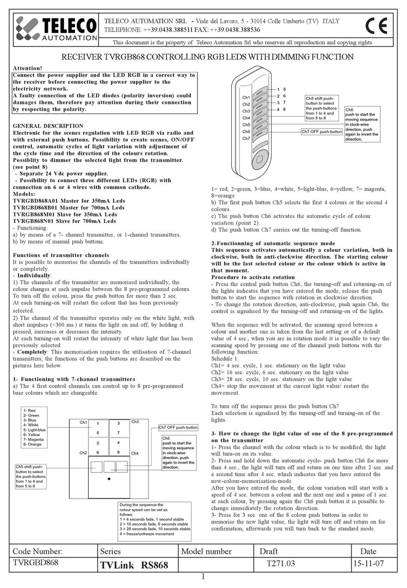
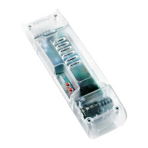
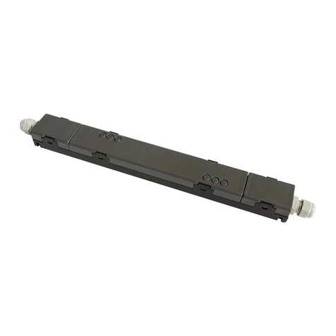
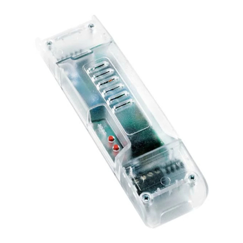
  9. TELECO AUTOMATION TVRGBDU868NT24 User manual

TELECO AUTOMATION TVRGBDU868NT24 User manual

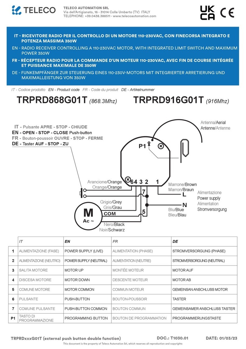
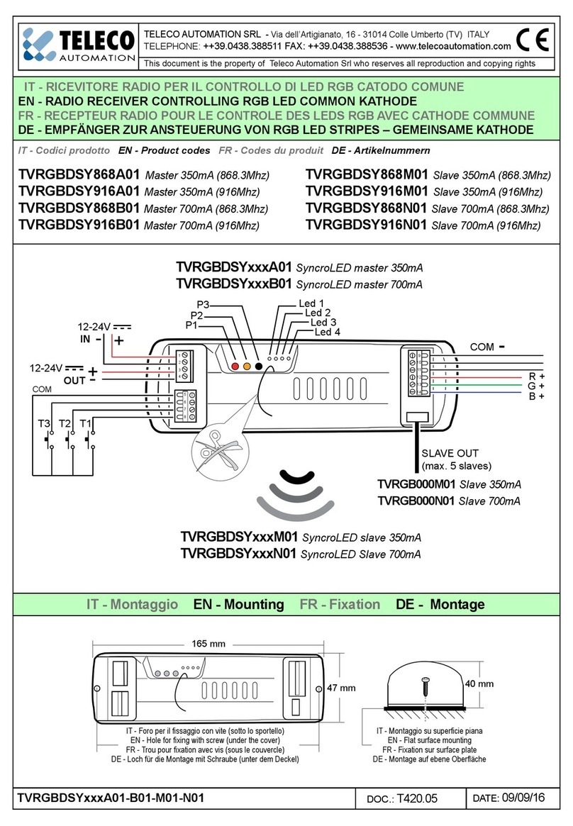
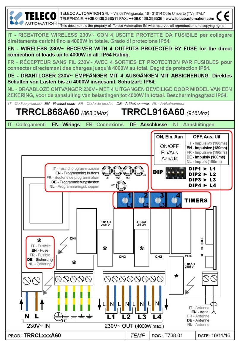
TELECO AUTOMATION SRL - Via dell’Artigianato, 16 - 31014 Colle Umberto (TV) ITALY
TELEPHONE: ++39.0438.388511 FAX: ++39.0438.388536 - www.telecoautomation.com
This document is the property of Teleco Automation Srl who reserves all reproduction and copying rights
DOC.: Temp.
TVRGBDUxxxNT24 DATE: 23/10/14
1
1
3
2
CLICK!!!
CLICK!!!
4
5
TVRGBDU868NT24 (868.3Mhz)
TVRGBDU916NT24 (916Mhz)
IT - RICEVITORE RADIO PER IL CONTROLLO DI STRIP LED RGB ANODO COMUNE
EN - RADIO RECEIVER CONTROLLING RGB LED STRIPS COMMON ANODE
FR - RECEPTEUR RADIO POUR LE CONTROLE DES LEDS RGB AVEC ANODE COMMUNE
DE - EMPFÄNGER ZUR ANSTEUERUNG VON RGB LED STRIPES – GEMEINSAME ANODE
IT - Codice prodotto
EN - Product code
FR - Code du produit
DE - Artikelnummer
IT - Dimensioni EN - Dimensions FR - Dimensions DE - Abmessungen
ANT
RED
STRIP
10
GREEN
BLUE
COM
COM
COM
9
8
7
6
5
GND
GND
+24V
POWER
SUPPLAY
ANT
RED
STRIP
10
GREEN
BLUE
COM
COM
COM
9
8
7
6
5
GND
GND
+24V
POWER
SUPPLAY
ANT
RED
STRIP
10
GREEN
BLUE
COM
COM
COM
9
8
7
6
5
GND
GND
+24V
POWER
SUPPLAY
252 mm
IT - Fori di fissaggio
EN - Fixing holes
FR - Trous de fixation
DE - Befestigungslöcher
331 mm
342 mm
30 mm 16 mm
10 mm
20 mm
ANT
RED
STRIP
10
GREEN
BLUE
COM
COM
COM
9
8
7
6
5
GND
GND
+24V
POWER
SUPPLAY
ANT
RED
STRIP
10
GREEN
BLUE
COM
COM
COM
9
8
7
6
5
GND
GND
+24V
POWER
SUPPLAY
ANT
RED
STRIP
10
GREEN
BLUE
COM
COM
COM
9
8
7
6
5
GND
GND
+24V
POWER
SUPPLAY
252 mm
IT - Fori di fissaggio
EN - Fixing holes
FR - Trous de fixation
DE - Befestigungslöcher
331 mm
342 mm
30 mm 16 mm
10 mm
20 mm
IT - Coperchio
EN - Lid
FR - Couvercle
DE - Deckels
P1
P2
P3
IT - Coperchio
EN - Lid
FR - Couvercle
DE - Deckels
IT - Staffa di ssaggio
EN - Fixing bracket
FR - Support de xation
DE - Befestigungswinkel
IT - Staffa di ssaggio
EN - Fixing bracket
FR - Support de xation
DE - Befestigungswinkel
IT - Alimentazione
EN - Power supply
FR - Alimentation
DE - Stromversorgung
IT - Uscite LED
EN - LED output
FR - LED sorties
DE - LED Ausgang
2
IT - Montaggio EN - Mounting FR - Fixation DE - Montage
1
2
3
5
4
1
1
3
2
CLICK!!!
CLICK!!!
4
5
IT - 1. Inserire la staffa nelle apposite guide. 2. Premere no in fondo.
EN - 1. Insert the bracket in the proper guides. 2. Press all the way down.
FR - 1. Insérer le support dans les guides. 2. Appuyer jusqu’au fond.
DE - 1. Befestigungswinkel in die entsprechenden Schienen einführen. 2. Bis zum
Anschlag drücken.
1
2
2
1
IT - Montare le staffe di ssaggio EN - Mounting the xing brackets
FR - Fixer les supports de xation DE - Befestigungswinkel montieren
IT - Aprire i coperchi
EN - Opening the lids
FR - Ouvrir les couvercles
DE - Die Deckel öffnen
IT
1. Fare leva su un gancio.
2. Sollevare il lato del coperchio.
3. Fare leva sull’altro gancio.
4. Rimuovere il coperchio.
EN
1. Lever a clip.
2. Lift the lid’s side up.
3. Lever the other clip.
4. Remove the lid.
IT - Chiudere i coperchi
EN - Closing the lids
FR - Entrées laires
DE - Die Deckel schließen
EN
1. PLace the lid.
2. Check the direction.
3. Press all the way down.
4-5. Check that the lid is
completely closed.
FR
1. Soulever en faisant levier sur
un crochet. 2. Soulever le côté
du couvercle. 3. Soulever en
faisant levier sur l’autre crochet.
4. Enlever le couvercle.
FR
1. Positionner le couvercle.
2. Vérier le sens.
3. Appuyer jusqu’au fond.
4-5. S’assurer que le
couvercle soit fermé
complètement.
IT
1. Posizionare il coperchio.
2. Controllare il verso.
3. Premere no in fondo
4-5. Assicurarsi che il
coperchio sia chiuso
completamente.
DE
1. Eine Klemme hebeln.
2. Die Seite des Deckels anheben.
3. Die andere Klemme hebeln.
4. Den Deckel entfernen.
DE
1. Deckel positionieren.
2. Richtung überprüfen.
3. Bis zum Anschlag drücken.
4-5. Sich vergewissern
dass der Deckel vollständig
geschlossen ist.
3
IT - Attenzione: non invertire la polarità dei led!
EN - Attention: do not invert the polarity of the led!
FR - Attention: ne pas invérser la polarité des leds!
DE - Achtung: Polung der LEDs nicht invertieren!
ANT
RED
STRIP
10
GREEN
BLUE
COM
COM
COM
9
8
7
6
5
GND
GND
+24V
POWER
SUPPLAY
ANT
RED
STRIP
10
GREEN
BLUE
COM
COM
COM
9
8
7
6
5
GND
GND
+24V
POWER
SUPPLAY
ANT
RED
STRIP
10
GREEN
BLUE
COM
COM
COM
9
8
7
6
5
GND
GND
+24V
POWER
SUPPLAY
ANT
GND
GND
+24V
POWER
SUPPLAY
RED
STRIP
10
GREEN
BLUE
COM
COM
COM
9
8
7
6
5
RED
STRIP
10
GREEN
BLUE
COM
COM
COM
9
8
7
6
5
-L1
-L2
-L3
+COM
-
+
ANT
GND
GND
+24V
POWER
SUPPLAY
12-24Vdc IN
+
-
LINE
IN
12-24Vdc
OUT
L
N
ANT.
GND
ANT
RED
STRIP
10
GREEN
BLUE
COM
COM
COM
9
8
7
6
5
GND
GND
+24V
POWER
SUPPLAY
RED
STRIP
10
GREEN
BLUE
COM
COM
COM
9
8
7
6
5
RED
STRIP
10
GREEN
BLUE
COM
COM
COM
9
8
7
6
5
-
-
+COM
+COM
-
+
ANT
GND
GND
+24V
RED
STRIP
10
GREEN
BLUE
COM
COM
COM
9
8
7
6
5
RED
STRIP
10
GREEN
BLUE
COM
COM
COM
9
8
7
6
5
- R
- G
- B
+ COM
-
+
...
RED
STRIP
10
GREEN
BLUE
COM
COM
COM
9
8
7
6
5
ANT
RED
STRIP
10
GREEN
BLUE
COM
COM
COM
9
8
7
6
5
GND
GND
+24V
POWER
SUPPLAY
ANT
RED
STRIP
10
GREEN
BLUE
COM
COM
COM
9
8
7
6
5
GND
GND
+24V
POWER
SUPPLAY
ANT
RED
STRIP
10
GREEN
BLUE
COM
COM
COM
9
8
7
6
5
GND
GND
+24V
POWER
SUPPLAY
ANT
GND
GND
+24V
POWER
SUPPLAY
RED
STRIP
10
GREEN
BLUE
COM
COM
COM
9
8
7
6
5
RED
STRIP
10
GREEN
BLUE
COM
COM
COM
9
8
7
6
5
-L1
-L2
-L3
+COM
-
+
ANT
GND
GND
+24V
POWER
SUPPLAY
12-24Vdc IN
+
-
LINE
IN
12-24Vdc
OUT
L
N
ANT.
GND
ANT
RED
STRIP
10
GREEN
BLUE
COM
COM
COM
9
8
7
6
5
GND
GND
+24V
POWER
SUPPLAY
RED
STRIP
10
GREEN
BLUE
COM
COM
COM
9
8
7
6
5
RED
STRIP
10
GREEN
BLUE
COM
COM
COM
9
8
7
6
5
-
-
+COM
+COM
-
+
ANT
GND
GND
+24V
RED
STRIP
10
GREEN
BLUE
COM
COM
COM
9
8
7
6
5
RED
STRIP
10
GREEN
BLUE
COM
COM
COM
9
8
7
6
5
- R
- G
- B
+ COM
-
+
...
RED
STRIP
10
GREEN
BLUE
COM
COM
COM
9
8
7
6
5
IT -Attenzione: l’alimentazione fornita al ricevitore deve corrispondere
al voltaggio del carico!
EN - Attention: the power supply connected to the receiver must
correspond to the voltage of the load!
FR - Attention: l’alimentation fournie au récepteur doit correspondre à
la tension de la charge!
DE - Achtung: Die Stromversorgung des Empfängers muss mit der
Spannung der Last übereinstimmen!
IT - Collegamenti EN - Wirings
FR - Connexions DE - Anschlüsse
IT - Dispositivi di comando wireless EN - Wireless command devices
FR - Dispositifs de commande sans l DE - Drahtlose Steuerungsgeräte
IT - Trasmettitore 7 canali (p.4-5)
EN - 7 channels transmitter (p.4 - 5)
FR - Emetteur à 7 canaux (p.4-5)
DE - 7-Kanal Sender (S.4-5)
IT - Canale singolo di comando (p.5)
EN - Single command channel (p.5)
FR - Canal individuel de commande (p.5)
DE - Einzel- Kanal für Befehle (S.5)
IT - Trasmettitore dedicato per comandare gli scenari creati con Freeled (p.9-10)
(CH1..CH4 = Scenari 1..4, tasto >2s. = OFF)
EN - Reserved transmitter to command the scenes created by means of Freeled (p.9-10)
(CH1..CH4 = Scenes 1..4, button >2s. = OFF)
FR - Emetteur dédié au contrôle des scenarios créés par le système Freeled (p.9-10)
(CH1..CH4 = Scenarios 1..4, bouton >2s. = OFF)
DE - Sender für die Steuerung der mit Freeled erstellten Szenen (S.9-10)
(CH1..CH4 = Szenen 1..4, Taste >2sek. = OFF)
IT - Trasmettitore USB EN - USB transmitter
FR - Emetteur USB DE - USB Sender
.
.
.
1
2
3
4
5
6
7
ON (EIN)
3
21 4
143
2
IT - Ogni tasto può essere associato a un ricevitore. Vedere p.9 e
le istruzioni del software Freeled per dettagli. EN - Each button can
be associated to a receiver. See p.9 and the instructions of Freeled
software for details. FR - Chaque bouton peut être associé à un
récepteur. Voir p.9 et les notices du software RGB PC pour tous
détails. DE - Jede Taste kann einem Empfänger zugeordnet werden.
Siehe Seite 9 und Anleitung der RGB PC Software für Details.
IT - 1. Accendere il trasmettitore con il tasto ON;
2. Premere il tasto associato al ricevitore (tramite
codice identicativo o memorizzazione p.10); 3.
I led collegati si accendono prima di giallo, poi di
verde (se OK) o rosso (in caso di errore).
EN - 1. Turn on the transmitter with the button ON;
2. Press the button associated to the receiver (by
means of ID code or memorization p.10); 3. The
connected led turn on with yellow colour, then
green (if OK) or red (in case of any error).
FR - 1.Allumer l’émetteur en appuyant sur le bouton
ON; 2. Appuyer sur le bouton associé au récepteur
(via code d’identication ou mémorisation p.10);
3. Les LED connectées s’allument d’abord en
jaune, ensuite en vert (si OK) ou en rouge (en cas
d’erreur).
DE - 1. Schalten Sie den Sender mit der Taste On
ein. 2. Drücken Sie die dem Empfänger zugeordnete
(mittels ID Code oder Einlernung S.10); 3. Die
angeschlossenen Leds schalten zuerst auf Gelb,
dann auf Grün (falls OK) oder Rot (Fehler).
TVTXQ868U07
ANT
RED
STRIP
10
GREEN
BLUE
COM
COM
COM
9
8
7
6
5
GND
GND
+24V
POWER
SUPPLAY
ANT
RED
STRIP
10
GREEN
BLUE
COM
COM
COM
9
8
7
6
5
GND
GND
+24V
POWER
SUPPLAY
ANT
RED
STRIP
10
GREEN
BLUE
COM
COM
COM
9
8
7
6
5
GND
GND
+24V
POWER
SUPPLAY
ANT
GND
GND
+24V
POWER
SUPPLAY
RED
STRIP
10
GREEN
BLUE
COM
COM
COM
9
8
7
6
5
RED
STRIP
10
GREEN
BLUE
COM
COM
COM
9
8
7
6
5
-L1
-L2
-L3
+COM
-
+
ANT
GND
GND
+24V
POWER
SUPPLAY
12-24Vdc IN
+
-
LINE
IN
12-24Vdc
OUT
L
N
ANT.
GND
ANT
RED
STRIP
10
GREEN
BLUE
COM
COM
COM
9
8
7
6
5
GND
GND
+24V
POWER
SUPPLAY
RED
STRIP
10
GREEN
BLUE
COM
COM
COM
9
8
7
6
5
RED
STRIP
10
GREEN
BLUE
COM
COM
COM
9
8
7
6
5
-
-
+COM
+COM
-
+
ANT
GND
GND
+24V
RED
STRIP
10
GREEN
BLUE
COM
COM
COM
9
8
7
6
5
RED
STRIP
10
GREEN
BLUE
COM
COM
COM
9
8
7
6
5
- R
- G
- B
+ COM
-
+
...
RED
STRIP
10
GREEN
BLUE
COM
COM
COM
9
8
7
6
5
1 2
ANT
RED
STRIP
10
GREEN
BLUE
COM
COM
COM
9
8
7
6
5
GND
GND
+24V
POWER
SUPPLAY
ANT
RED
STRIP
10
GREEN
BLUE
COM
COM
COM
9
8
7
6
5
GND
GND
+24V
POWER
SUPPLAY
ANT
RED
STRIP
10
GREEN
BLUE
COM
COM
COM
9
8
7
6
5
GND
GND
+24V
POWER
SUPPLAY
ANT
GND
GND
+24V
POWER
SUPPLAY
RED
STRIP
10
GREEN
BLUE
COM
COM
COM
9
8
7
6
5
RED
STRIP
10
GREEN
BLUE
COM
COM
COM
9
8
7
6
5
-L1
-L2
-L3
+COM
-
+
ANT
GND
GND
+24V
POWER
SUPPLAY
12-24Vdc IN
+
-
LINE
IN
12-24Vdc
OUT
L
N
ANT.
GND
ANT
RED
STRIP
10
GREEN
BLUE
COM
COM
COM
9
8
7
6
5
GND
GND
+24V
POWER
SUPPLAY
RED
STRIP
10
GREEN
BLUE
COM
COM
COM
9
8
7
6
5
RED
STRIP
10
GREEN
BLUE
COM
COM
COM
9
8
7
6
5
-
-
+COM
+COM
-
+
ANT
GND
GND
+24V
RED
STRIP
10
GREEN
BLUE
COM
COM
COM
9
8
7
6
5
RED
STRIP
10
GREEN
BLUE
COM
COM
COM
9
8
7
6
5
- R
- G
- B
+ COM
-
+
...
RED
STRIP
10
GREEN
BLUE
COM
COM
COM
9
8
7
6
5
1
2
4
colors 1 or 2
selection
OFF
speed 1
colors 1
colors 2
speed 2
speed 3
pause/play
cycle
activation/
direction
CH1
CH2
CH3
CH4
CH5
CH6
CH7
*** ***
EN **
IT - Mantenere premuto i tasti CH1..4 per regolare
l’intensità dei colori selezionati.
EN - Keep the buttons CH1..4 pressed to dim the
light intensity of the selected colours.
FR - Garder appuyés les boutons CH1..4 pour régler
l’intensité des couleurs sélectionnées.
DE - Halten Sie die Tasten CH1..4 gedrückt um die
jeweilige Farbe rauf oder runter zu dimmen.
* Velocità
Speed
Vitesse
Geschwindigkeit
Fisso
Solid
Fixe
Konstant
Variazione
Moving
Variation
Wechsel
11 s. 4 s.
26 s. 16 s.
310 s. 28 s.
IT - Trasmettitore 7 canali EN - 7 channels transmitter FR - Emetteur à 7 canaux DE - 7 Kanal Sender
selezione
colori 1 o 2
OFF
velocità 1
colori 1
colori 2
velocità 2
velocità 3
pausa/play
attiva/inverti
ciclo
CH1
CH2
CH3
CH4
CH5
CH6
CH7
*** ***
choix des
couleurs 1 ou 2
OFF
vitesse 1
couleurs 1
couleurs 2
vitesse 2
vitesse 3
pause/play
Démarrage/
inversion
du cycle
CH1
CH2
CH3
CH4
CH5
CH6
CH7
*** ***
Wähle
Farben 1 oder 2
AUS
Geschwindigkeit
1
Farben 1
Farben 2
Pause/Start
Starte Sequenz/
Umkehrung
CH1
CH2
CH3
CH4
CH5
CH6
CH7
***
Geschwindigkeit
2
Geschwindigkeit
3
***
1s. 4s. 1s. 4s. 1s. 4s. 1s. 4s. 1s. 4s. 1s. 4s. 1s. 4s. 1s.
6s. 16s. 6s. 16s. 6s. 16s. 6s. 16s. 6s. 16s. 6s. 16s. 6s. 16s. 6s.
10s. 28s. 10s. 28s. 10s. 28s. 10s. 28s. 10s. 28s. 10s. 28s. 10s. 28s. 10s.
***
# Col.
(Farben)
1
2
3
4
5
6
7
8
Rosso - Red - Rouge - Rot
Verde - Green - Vert - Grün
Blu - Blue - Bleu - Blau
Bianco caldo - Warm white
Blanc chaud - Warmweiß
IT
Ciano - Cyan - Cyan - Hellblau
Giallo - Yellow - Jaune - Gelb
Magenta - Magenta - Magenta - Anilinrot
Bianco freddo - Cold white
Blanc froid - Kaltweiß
DE
FR
5
IT - Memorizzazione codici radio (con P2) EN - Radio codes memorization (with P2)
FR - Mémorisation codes radio (avec P2) DE - Einlernung Sendekanäle (mit P2)
** IT - Ultimo colore attivo prima dello spegnimento. EN - Last activated colour before turning-off. FR - Dernière couleur activèe avant l’éteignement. DE - Letzte aktive Farbe vor dem Ausschalten.
e tenere premuto.
and keep it pressed.
et garder appuyé.
und halten gedrückt.
IT - Premere P2
EN - Press P2
FR - Appuyer P2
DE - P2 Drücken
. . .
1.1P2
IT - Premere il tasto del trasmettitore
relativo al codice da memorizzare.
EN - Press the button of the transmitter
relative to the code to memorize.
FR - Appuyer sur le bouton de l’émetteur
concernant le code à mémoriser.
DE - Drücken Sie die Sendertaste die auf
den zu speichernden Code bezogen ist.
. . .
suono continuo
continuous sound
son continu
Dauerton
suono intermittente
intermittent sound
son intermittent
intermittierender Ton
= OK!
*IT - Il buzzer emette un bip ad ogni pressione. EN - The buzzer will make a beep each press. FR - L’avertisseur sonore émet un bip à chaque appui. DE - Das Gerät quittiert jeden Druck mit einem Ton.
in funzione della memorizzazione desiderata,
according to the desired memorization,
en fonction de la mémorisation souhaitée,
entsprechend der gewünschten Einlernung,
1
IT - 7canali (vedere descrizione p.4)
EN - 7channels (see description p.4)
FR - 7canaux (voir description p.4)
DE - 7Kanäle (siehe Beschreibung S.4)
2
IT - 1 tasto per la selezione colore
EN - 1 button for the colour selection
FR - 1 bouton pour la sélection couleur
DE - 1 Taste: für Farbfunktion
3
IT - 1 tasto con funzione: ON
EN - 1 button with function: ON
FR - 1 bouton avec fonction: ON
DE - 1 Taste mit Funktion: EIN
4
IT - 1 tasto con funzione: OFF
EN - 1 button with function: OFF
FR - 1 bouton avec fonction: OFF
DE - 1 Taste mit Funktion: AUS
5
IT - 1 tasto con funzione: bianco caldo
EN - 1 button with function: warm white
FR - 1 bouton avec fonction: blanc chaud
DE - 1 Taste mit Funktion: Warmweiß
6
IT - 1 tasto con funzione: bianco freddo
EN - 1 button with function: cold white
FR - 1 bouton avec fonction: blanc froid
DE - 1 Taste mit Funktion: Kaltweiß
volte times
fois male
volte times
fois male
volte times
fois male
volte times
fois male
volta time
fois mal
volte times
fois male
*
**
( )
= OFF
(AUS)
> 2s.
( )
= DIMMER
ꜛ ꜜ
> 1s.
( )
= ON/OFF
(EIN/AUS)
< 1s.
. . .
< 1s.
( )
= DIMMER
ꜛ ꜜ
> 1s.
( )
= ON/OFF
(EIN/AUS)
< 1s.
ANT
RED
STRIP
10
GREEN
BLUE
COM
COM
COM
9
8
7
6
5
GND
GND
+24V
POWER
SUPPLAY
ANT
RED
STRIP
10
GREEN
BLUE
COM
COM
COM
9
8
7
6
5
GND
GND
+24V
POWER
SUPPLAY
ANT
RED
STRIP
10
GREEN
BLUE
COM
COM
COM
9
8
7
6
5
GND
GND
+24V
POWER
SUPPLAY
ANT
GND
GND
+24V
POWER
SUPPLAY
RED
STRIP
10
GREEN
BLUE
COM
COM
COM
9
8
7
6
5
RED
STRIP
10
GREEN
BLUE
COM
COM
COM
9
8
7
6
5
-L1
-L2
-L3
+COM
-
+
ANT
GND
GND
+24V
POWER
SUPPLAY
12-24Vdc IN
+
-
LINE
IN
12-24Vdc
OUT
L
N
ANT.
GND
ANT
RED
STRIP
10
GREEN
BLUE
COM
COM
COM
9
8
7
6
5
GND
GND
+24V
POWER
SUPPLAY
RED
STRIP
10
GREEN
BLUE
COM
COM
COM
9
8
7
6
5
RED
STRIP
10
GREEN
BLUE
COM
COM
COM
9
8
7
6
5
-
-
+COM
+COM
-
+
ANT
GND
GND
+24V
RED
STRIP
10
GREEN
BLUE
COM
COM
COM
9
8
7
6
5
RED
STRIP
10
GREEN
BLUE
COM
COM
COM
9
8
7
6
5
- R
- G
- B
+ COM
-
+
...
RED
STRIP
10
GREEN
BLUE
COM
COM
COM
9
8
7
6
5
P2
6
. . .
IT - Premere il tasto P3 del trasmettitore ... premere il tasto relativo ad un codice memorizzato... premere il tasto relativo al nuovo codice.
EN - Press the button P3 of the transmitter ... press the button relative to a memorized code ... press the button relative to the new code.
FR - Appuyer sur le bouton P3 de l’émetteur ... appuyer sur le bouton concernant un code mémorisé ... appuyer sur le bouton concernant le nouveau code.
DE - Drücken Sie die Taste P3 des Senders ... Drücken Sie die auf den gespeicherten Code bezogene Taste... Drücken Sie die auf den neuen Code bezogene Taste.
1 s.< 5 s. < 5 s.
IT - Premere tre volte il tasto P3 del trasmettitore...
EN - Press three times the button P3 of the transmitter...
FR - Appuyer trois fois sur le bouton P3 de l’émetteur...
DE - Drücken Sie drei mal die Taste P3 des Senders ...
x 3
premere il tasto relativo al codice da cancellare.
press the button relative to the code to delete.
appuyer sur le bouton concernant le code à effacer.
drücken Sie die auf den löschenden Code bezogene Taste.
P3
IT - Memorizzazione remota di ulteriori codici radio EN - Remote memorization of further radio codes
FR - Mémorisation à distance d’autres codes radio DE - Fern- Speicherung von weiteren Sendekanäle
P3
IT - Cancellazione remota di un codice radio EN - Remote deletion of a radio code
FR - Effacement à distance d’un code radio DE - Fern- Löschung eines Sendekanäle
IT - Il tasto P3 si trova all’interno del trasmettitore. EN - P3 button is located inside the transmitter. FR - Le bouton P3 se trouve à l’intérieur de l’émetteur. DE - Die Taste P3 bendet sich im Inneren des Senders.
IT - Il tasto P3 si trova all’interno del trasmettitore. Il codice radio aggiunto avrà le stesse funzioni del codice usato per l’inserimento. La procedura è compatibile con qualsiasi tipo di trasmettitore.
EN - P3 button is located inside the transmitter. The added radio code will have the same functions of the code used for the memorization. This procedure is compatible with any type of transmitter.
FR - Le bouton P3 se trouve à l’intérieur de l’émetteur. Le code radio ajouté aura les mêmes fonctions que le code utilisé pour la mémorisation. La procédure est compatible avec n’importe quel type d’émetteur.
DE - Die Taste P3 bendet sich im Inneren des Senders. Der hinzugefügte Sendekanal wird dieselben Funktionen des Codes haben welcher für die Einlernung verwendet wurde. Die Prozedur kann mit
allen Arten von Sendern durchgeführt werden.
suono continuo
continuous sound
son continu
Dauerton
suono intermittente
intermittent sound
son intermittent
intermittierender Ton
= OK!
suono continuo
continuous sound
son continu
Dauerton
suono continuo
continuous sound
son continu
Dauerton
suono continuo
continuous sound
son continu
Dauerton
= OK!
< >
>
nuovo new
nouveau neuen
7
IT - Trasmettitore 7 canali memorizzato
EN - Memorized 7 channels transmitter
FR - Emetteur à 7 canaux mémorisé
DE - Eingelernter 7-Kanal Sender
IT - Uscire con CH7
EN - Exit by CH7
FR - Sortir par CH7
DE - Beenden Sie mit CH7
*
IT - Memorizzare il colore desiderato tenendo
premuto 3s. il tasto da associare (CH1..4).
EN - Memorize the desired colour keeping the
button to associate (CH1..4) pressed 3s.
FR - Mémoriser la couleur choisie en gardant
appuyé pour 3s. le bouton à associer (CH1..4).
DE - Speichern Sie die gewünschte Farbe indem Sie
die zuzuordnende Taste (CH1…4) 3S. lang Drücken.
IT - Tenere premuto CH6 più di 4s. e
rilasciare dopo la seconda accensione.
EN - Keep CH6 pressed more than 4s. and
release after the second turning on.
FR - Garder appuyé CH6 pendant 4s. au min.
et relâcher après le clignotement de l’éclairage.
DE - Halten Sie CH6 länger als 4Sek. gedrückt
und lassen Sie nach dem zweiten Anschalten los.
CH6
1 2
. . .
*IT - Rotazione automatica dei colori (1 s. sso + 4 s.variazione). Premendo nuovamente il tasto CH6 è possibile cambiare subito il senso di rotazione.
EN - Automatic colours rotation (1 s. solid + 4 s. moving). Pressing again the button CH6 it is possible to change immediately the rotation direction.
FR - Variation de couleur automatique (1 s. xe + 4 s. variation). En appuyant de nouveau sur la touche CH6 on peut changer immédiatement le sens de rotation.
DE - Automatische Farbwechsel (1 Sek. konstant + 4 Sek. Wechsel). Durch Drücken des Tasters CH6 können Sie die Drehrichtung ändern.
CH7
IT - Modicare i colori standard EN - Modifying the preset colours
FR - Modier les couleurs standards DE - Standard- Farben ändern
> 4s.
4
8
7
6
5
3
2
1
3s.
(AUTOM.)
8
IT - Funzioni con P3 EN - Functions with P3
FR - Fonctions avec P3 DE - Funktionen mit P3
1.1P3
*IT - Il buzzer emette un bip ad ogni pressione. EN - The buzzer will make a beep each press. FR - L’avertisseur sonore émet un bip à chaque appui. DE - Das Gerät quittiert jeden Druck mit einem Ton.
in base alla funzione desiderata,
according to the desired function,
selon la fonction souhaitée,
entsprechend der gewünschten funktion,
1
IT - Reset colori standard (vedere p.4)
EN - Preset colours reset (see p.4)
FR - Reset des couleurs standards (voir p.4)
DE - Reset voreingestellte Farben (siehe S.4)
volta time
fois mal
*
e tenere premuto.
and keep it pressed.
et garder appuyé.
und halten gedrückt.
IT - Premere il tasto del trasmettitore relativo al codice da cancellare.
EN - Press the button of the transmitter relative to the code to delete.
FR - Appuyer sur le bouton de l’émetteur concernant le code à effacer.
DE - Drücken Sie die Sendertaste die auf den zu löschenden Code bezogen ist
. . .
IT - Premere P3
EN - Press P3
FR - Appuyer P3
DE - P3 Drücken
. . .
2
IT - Cancellazione di un singolo codice radio
EN - Deletion of a single radio code
FR - Effacement d’un single code radio
DE - Löschung eines einzelnen Sendekanäle
volte times
fois male
*
3
IT - Cancellazione di tutti i codici radio
EN - Deletion of all the radio codes
FR - Effacement de tous les codes radio
DE - Löschung aller Sendekanäle
volte times
fois male
*
volte times
fois male
*Attivazione - Activation
Activation - Aktivierung
. . .
LED4
ON
Disattivazione - Deactivation
Désactivation - Deaktivierung
suono continuo
continuous sound
son continu
Dauerton
suono intermittente
intermittent sound
son intermittent
intermittierender Ton = OK!
suono continuo continuous sound
son continu Dauerton
= OK!
. . .
10 s.
suono intermittente
intermittent sound
son intermittent
intermittierender Ton
10 s.
10 s.
= OK!
4
IT - Attivazione/disattivazione memoria
dell’ultimo valore di intensità luminosa
EN - Activation/deactivation of the memory
of the last light intensity value
FR - Activation/désactivation de la mémoire
à la dernière valeur d’intensité lumineuse
DE - Aktivierung/ Deaktivierung Speicher
letzter Wert der Lichtintensität
ANT
RED
STRIP
10
GREEN
BLUE
COM
COM
COM
9
8
7
6
5
GND
GND
+24V
POWER
SUPPLAY
ANT
RED
STRIP
10
GREEN
BLUE
COM
COM
COM
9
8
7
6
5
GND
GND
+24V
POWER
SUPPLAY
ANT
RED
STRIP
10
GREEN
BLUE
COM
COM
COM
9
8
7
6
5
GND
GND
+24V
POWER
SUPPLAY
ANT
GND
GND
+24V
POWER
SUPPLAY
RED
STRIP
10
GREEN
BLUE
COM
COM
COM
9
8
7
6
5
RED
STRIP
10
GREEN
BLUE
COM
COM
COM
9
8
7
6
5
-L1
-L2
-L3
+COM
-
+
ANT
GND
GND
+24V
POWER
SUPPLAY
12-24Vdc IN
+
-
LINE
IN
12-24Vdc
OUT
L
N
ANT.
GND
ANT
RED
STRIP
10
GREEN
BLUE
COM
COM
COM
9
8
7
6
5
GND
GND
+24V
POWER
SUPPLAY
RED
STRIP
10
GREEN
BLUE
COM
COM
COM
9
8
7
6
5
RED
STRIP
10
GREEN
BLUE
COM
COM
COM
9
8
7
6
5
-
-
+COM
+COM
-
+
ANT
GND
GND
+24V
RED
STRIP
10
GREEN
BLUE
COM
COM
COM
9
8
7
6
5
RED
STRIP
10
GREEN
BLUE
COM
COM
COM
9
8
7
6
5
- R
- G
- B
+ COM
-
+
...
RED
STRIP
10
GREEN
BLUE
COM
COM
COM
9
8
7
6
5
P3
ANT
RED
STRIP
10
GREEN
BLUE
COM
COM
COM
9
8
7
6
5
GND
GND
+24V
POWER
SUPPLAY
ANT
RED
STRIP
10
GREEN
BLUE
COM
COM
COM
9
8
7
6
5
GND
GND
+24V
POWER
SUPPLAY
ANT
RED
STRIP
10
GREEN
BLUE
COM
COM
COM
9
8
7
6
5
GND
GND
+24V
POWER
SUPPLAY
ANT
GND
GND
+24V
POWER
SUPPLAY
RED
STRIP
10
GREEN
BLUE
COM
COM
COM
9
8
7
6
5
RED
STRIP
10
GREEN
BLUE
COM
COM
COM
9
8
7
6
5
-L1
-L2
-L3
+COM
-
+
ANT
GND
GND
+24V
POWER
SUPPLAY
12-24Vdc IN
+
-
LINE
IN
12-24Vdc
OUT
L
N
ANT.
GND
ANT
RED
STRIP
10
GREEN
BLUE
COM
COM
COM
9
8
7
6
5
GND
GND
+24V
POWER
SUPPLAY
RED
STRIP
10
GREEN
BLUE
COM
COM
COM
9
8
7
6
5
RED
STRIP
10
GREEN
BLUE
COM
COM
COM
9
8
7
6
5
-
-
+COM
+COM
-
+
ANT
GND
GND
+24V
RED
STRIP
10
GREEN
BLUE
COM
COM
COM
9
8
7
6
5
RED
STRIP
10
GREEN
BLUE
COM
COM
COM
9
8
7
6
5
- R
- G
- B
+ COM
-
+
...
RED
STRIP
10
GREEN
BLUE
COM
COM
COM
9
8
7
6
5
ANT
RED
STRIP
10
GREEN
BLUE
COM
COM
COM
9
8
7
6
5
GND
GND
+24V
POWER
SUPPLAY
ANT
RED
STRIP
10
GREEN
BLUE
COM
COM
COM
9
8
7
6
5
GND
GND
+24V
POWER
SUPPLAY
ANT
RED
STRIP
10
GREEN
BLUE
COM
COM
COM
9
8
7
6
5
GND
GND
+24V
POWER
SUPPLAY
ANT
GND
GND
+24V
POWER
SUPPLAY
RED
STRIP
10
GREEN
BLUE
COM
COM
COM
9
8
7
6
5
RED
STRIP
10
GREEN
BLUE
COM
COM
COM
9
8
7
6
5
-L1
-L2
-L3
+COM
-
+
ANT
GND
GND
+24V
POWER
SUPPLAY
12-24Vdc IN
+
-
LINE
IN
12-24Vdc
OUT
L
N
ANT.
GND
ANT
RED
STRIP
10
GREEN
BLUE
COM
COM
COM
9
8
7
6
5
GND
GND
+24V
POWER
SUPPLAY
RED
STRIP
10
GREEN
BLUE
COM
COM
COM
9
8
7
6
5
RED
STRIP
10
GREEN
BLUE
COM
COM
COM
9
8
7
6
5
-
-
+COM
+COM
-
+
ANT
GND
GND
+24V
RED
STRIP
10
GREEN
BLUE
COM
COM
COM
9
8
7
6
5
RED
STRIP
10
GREEN
BLUE
COM
COM
COM
9
8
7
6
5
- R
- G
- B
+ COM
-
+
...
RED
STRIP
10
GREEN
BLUE
COM
COM
COM
9
8
7
6
5
9
IT - FREELED: sistema completo per la gestione dell’illuminazione RGB di ambienti. Permette di creare atmosfere con innite possibilità di personalizzazione nella scelta di colori
ed effetti in 3 mosse. Il sistema comprende un software PC dedicato alla creazione degli scenari ed un trasmettitore con connessione USB (TVTXQ868U07) per inviare ai ricevitori
compatibili gli scenari con una semplice trasmissione radio. Le operazioni di creazione ed invio degli scenari possono essere effettuate anche in momenti e luoghi diversi.
EN - FREELED: a complete system for the management of RGB lighting of locations. It allows to create atmospheres with innite possibilities of customizations in colours and effects
setting, all in 3 steps. The system includes a dedicated PC software to create the scenes and a USB transmitter (TVTXQ868U07) to send the scenes to compatible receivers by
means of a simple radio transmission. Scenes creation and sending can be performed even in different time and place.
FR - FREELED: système complet pour la gestion d’éclairages RGB dans des ambiances. En trois étapes, il permet de créer des atmosphères avec possibilités innies de
personnalisation dans le choix de couleurs et effets. Le système comprend un logiciel pour ordinateur dédié à la réalisation des scenarios et un émetteur avec connexion USB
(TVTXQ868U07) pour l’envoi via radio des scenarios aux récepteurs compatibles. Les opérations de création et d’envoi des scenarios pourront être réalisées sans être obligatoirement
sur les lieux de l’installation.
DE - FREELED: ein komplettes System für die Steuerung von RGB Beleuchtung in Ihrer Umgebung. Sie können damit unterschiedliche Atmosphären kreieren, mit einer endlosen
Wahl an Farben und Effekten in drei einfachen Schritten. Das Kit umfasst einen Sender mit USB-Anschluss (TVTXQ868U07) und eine spezielle PC Software, mit welcher Sie die
Szenen einfach über Funk an die kompatiblen Empfänger übermitteln können. Das Erstellen und Senden der Szenen kann in verschiedenen Momenten und von verschiedenen
Stellen aus vorgenommen werden.
21 3
IT - CREAZIONE SCENARI CON IL SOFTWARE.
Collegare il trasmettitore USB al PC ed utilizzare il
software per creare gli scenari.
EN - SCENES CREATION BY PC SOFTWARE.
Connect the USB transmitter to PC and use the
software to create the scenes.
FR - CREATION DE SCENARIOS GRACE
AU LOGICIEL. Connecter l’émetteur USB à
l’ordinateur et utiliser le logiciel pour créer les
scenarios.
DE - ERSTELLUNG SZENEN ÜBER PC
SOFTWARE. Schließen Sie den USB Sender
an den PC und erstellen Sie die Szenen mit der
Software.
IT - INVIO SCENARI. Se si conosce il codice identicativo
del ricevitore, l’invio e la ricezione degli scenari avvengono
automaticamente con un semplice comando, altrimenti memorizzare
il trasmettitore USB (vedi pag.10) ed applicare la procedura a pag.3.
EN - SCENES TRANSMISSION. In case the ID code of the receiver
is known, sending and receiving of the scenes is automatic, by
means of a simple command, otherwise memorize USB transmitter
(see page 10) and apply the procedure at page 3.
FR - ENVOI DE SCENARIOS. Si le code d’identication du
récepteur est connu, l’envoi et la réception des scenarios seront
faits automatiquement par une simple commande ; en cas contraire,
il faut mémoriser l’émetteur USB (voir à la page 10) et ensuite suivre
la procédure à la page 3.
DE - SENDUNG DER SZENEN. Wenn Sie den ID Code des
Empfängers kennen, werden die Szenen automatische mit einem
einfachen Befehl versendet und empfangen, andernfalls lernen Sie
den USB Sender ein (siehe Seite 10) und befolgen Sie Prozedur
auf Seite 3.
IT - UTILIZZO DEGLI SCENARI. Memorizzare un
nuovo trasmettitore con almeno 4 canali dedicato al
comando dei 4 scenari caricati (vedi pagina 10).
EN - USE OF THE SCENES. Memorize a new
transmitter with at least 4 channels, reserved for the
command of the 4 loaded scenes (see page 10).
FR - UTILISATION DES SCENARIOS. Mémoriser
un nouvel émetteur avec au moins 4 canaux dédiés
au contrôle des 4 scenarios (voir à la page 10).
DE - VERWENDUNG DER SZENEN. Lernen Sie
einen neuen Sender mit mindestens 4 Kanälen ein
für die Steuerung der 4 eingestellten Szenen (siehe
Seite 10).
10
IT - Funzioni con P1 (FREELED) EN - Functions with P1 (FREELED)
FR - Fonctions avec P1 (FREELED) DE - Funktionen mit P1 (FREELED)
1.1P1
*IT - Il buzzer emette un bip ad ogni pressione. EN - The buzzer will make a beep each press. FR - L’avertisseur sonore émet un bip à chaque appui. DE - Das Gerät quittiert jeden Druck mit einem Ton.
e tenere premuto.
and keep it pressed.
et garder appuyé.
und halten gedrückt.
IT - Premere P1
EN - Press P1
FR - Appuyer P1
DE - P1 Drücken
. . .
4
IT - Cancellare tutti i trasmettitori USB
(se non si opera con codici identicativi)
EN - Deleting all the USB transmitters
(if not working with ID codes)
FR - Effacer tous les émetteurs USB
(si non utilisation du code ID)
DE - Löschen aller USB Sender
(Für die Verwendung ohne ID Code)
volte times
fois male
*
in base alla funzione desiderata,
according to the desired function,
selon la fonction souhaitée,
entsprechend der gewünschten funktion,
3
IT - Cancellare un tasto del trasmettitore USB
(se non si opera con codici identicativi)
EN - Deleting one button of the USB transmitter
(if not working with ID codes)
FR - Effacer un bouton de l’émetteur USB
(si non utilisation du code ID)
DE - Löschen einer Taste des USB Senders
(Für die Verwendung ohne ID Code)
volte times
fois male
*
2
IT - Memorizzare un tasto del trasmettitore USB
(se non si opera con codici identicativi)
EN - Memorizing one button of the USB transmitter
(if not working with ID codes)
FR - Mémoriser un bouton de l’émetteur USB
(si non utilisation du code ID)
DE - Einlernen einer Taste des USB Senders
(Für die Verwendung ohne ID Code)
volte times
fois male
*
1
IT - Memorizzare un trasmettitore per
comandare gli scenari creati con Freeled
EN - Memorizing a transmitter to command
the scenes created by Freeled
FR - Mémoriser un émetteur pour commander
les scenarios créés par le Freeled
DE - Einlernen eines Senders um die mit der
Freeled erstellten Szenen zu steuern
volta time
fois mal
*
. . .
suono continuo
continuous sound
son continu
Dauerton
suono intermittente
intermittent sound
son intermittent
intermittierender Ton = OK!
10 s.
IT - Premere il tasto del trasmettitore relativo al codice da cancellare.
EN - Press the button of the transmitter relative to the code to delete.
FR - Appuyer sur le bouton de l’émetteur concernant le code à effacer.
DE - Drücken Sie die Sendertaste die auf den zu löschenden Code bezogen ist.
suono continuo continuous sound
son continu Dauerton
= OK!
. . .
suono intermittente
intermittent sound
son intermittent
intermittierender Ton
IT - Premere il tasto del trasmettitore relativo al codice da memorizzare.
EN - Press the button of the transmitter relative to the code to memorize.
FR - Appuyer sur le bouton de l’émetteur concernant le code à mémoriser.
DE - Drücken Sie die Sendertaste die auf den zu speichernden Code bezogen ist.
= OK!
suono intermittente intermittent sound
son intermittent intermittierender Ton
. . .
suono continuo
continuous sound
son continu
Dauerton
IT - Premere un tasto del trasmettitore 4/7/42 canali
EN - Press any button of the 4/7/42 channels transmitter
FR - Appuyer sur un bouton de l’émetteur à 4/7/42 canaux
DE - Einen 4/7/42-Kanal Sender drücken
= OK!
suono intermittente intermittent sound
son intermittent intermittierender Ton
. . .
suono continuo
continuous sound
son continu
Dauerton
ANT
RED
STRIP
10
GREEN
BLUE
COM
COM
COM
9
8
7
6
5
GND
GND
+24V
POWER
SUPPLAY
ANT
RED
STRIP
10
GREEN
BLUE
COM
COM
COM
9
8
7
6
5
GND
GND
+24V
POWER
SUPPLAY
ANT
RED
STRIP
10
GREEN
BLUE
COM
COM
COM
9
8
7
6
5
GND
GND
+24V
POWER
SUPPLAY
ANT
GND
GND
+24V
POWER
SUPPLAY
RED
STRIP
10
GREEN
BLUE
COM
COM
COM
9
8
7
6
5
RED
STRIP
10
GREEN
BLUE
COM
COM
COM
9
8
7
6
5
-L1
-L2
-L3
+COM
-
+
ANT
GND
GND
+24V
POWER
SUPPLAY
12-24Vdc IN
+
-
LINE
IN
12-24Vdc
OUT
L
N
ANT.
GND
ANT
RED
STRIP
10
GREEN
BLUE
COM
COM
COM
9
8
7
6
5
GND
GND
+24V
POWER
SUPPLAY
RED
STRIP
10
GREEN
BLUE
COM
COM
COM
9
8
7
6
5
RED
STRIP
10
GREEN
BLUE
COM
COM
COM
9
8
7
6
5
-
-
+COM
+COM
-
+
ANT
GND
GND
+24V
RED
STRIP
10
GREEN
BLUE
COM
COM
COM
9
8
7
6
5
RED
STRIP
10
GREEN
BLUE
COM
COM
COM
9
8
7
6
5
- R
- G
- B
+ COM
-
+
...
RED
STRIP
10
GREEN
BLUE
COM
COM
COM
9
8
7
6
5
P1
11
IT - Avvertenze EN - Warning FR - Avertissements DE - Achtung
IT - Prima di collegare l’alimentatore alla rete elettrica assicurarsi che l’alimentatore e i LED siano collegati correttamente al ricevitore. Un errato collegamento dei diodi LED
(inversione di polarità) potrebbe danneggiarli, fare pertanto molta attenzione al loro collegamento rispettando le polarità. L’alimentatore del dispositivo deve fornire la tensione e
la corrente richiesta dal dispositivo e dai led collegati. L’alimentatore deve essere conforme alla norma IEC60950-1 e protetto contro i corto circuiti e sovratensioni. All’accensione
il ricevitore riprende la condizione precedente allo spegnimento. Il prodotto non deve essere inglobato o appoggiato in prodotti isolanti come lana di vetro o polistirolo o prodotti
analoghi. Lasciare il contenitore il più arieggiato possibile.
EN - Connect the power supplier and the LED correctly to the receiver before connecting the power supplier to the mains supply. A faulty connection of the LED diodes (polarity
inversion) could damages them, therefore pay attention during their connection by respecting the polarity. The general power supply of the device has to be provided by a power
supplier which can supply the needed power and voltage. The power supply must be compliant with IEC60950-1 and must be protected against short circuit and overvoltage. At
the power-on the device resumes the status it had before the turning-off. The product must not be enclosed or placed with insulating material such as glass wool, polystyrene or
similar materials. Let the housing to be well-ventilated.
FR - Avant de brancher l’alimentation à la ligne électrique, s’assurer que l’alimentation et les LEDs soient branchées correctement au récepteur. Un branchement incorrect des
diodes LED (inversion de la polarité) peut les endommager, donc bien vérier les polarités lors du branchement. L’alimentation du dispositif doit fournir la tension et le courant
demandés par le dispositif et par les LED reliés. L’alimentation doit être conforme à la norme IEC60950-1 et il doit être protégé contre les courts-circuits et les surtensions. A la
mise sous-tension, le dernier état avant extinction (ON ou OFF) est restauré. Le produit ne doit pas être incorporé ou posé dans des matériaux isolants (comme bre de verre,
polystyrène ou similaires). Faire en sorte de maintenir le boitier dans un endroit sec et aéré.

DE - Verbinden Sie die Stromversorgung und die LEDs korrekt mit dem Empfänger bevor Sie die Stromversorgung an das Netz anschließen. Ein fehlerhafter Anschluss
(verkehrte Polung) kann die LEDs beschädigen. Der Stromversorger des Geräts muss das Gerät und die angeschlossenen LEDs mit der entsprechenden Spannung und Strom
versorgen. Der Stromversorger des Geräts muss das Gerät und die angeschlossenen LEDs mit der entsprechenden Spannung und Strom versorgen. Das Netzgerät muss
der Norm IEC60950-1 entsprechen und gegen Kurzschlüsse und Überspannungen gesichert sein. Mit power- on- reset werden die Einstellungen vor dem Abschalten wieder
hergestellt. Das Gerät darf nicht eingehaust oder durch Isolationsmaterial wie Glaswolle, Polystyrol oder ähnlichem umbaut werden. Das Gehäuse muss eine ausreichende
Durchlüftung haben.
IT - Con la presente Teleco Automation s.r.l. dichiara che il prodotto è conforme ai requisiti essenziali, ed alle altre disposizioni pertinenti, stabilite dalla direttiva 1999/5/CE.
La dichiarazione di conformità può essere consultata sul sito: www.telecoautomation.com/ce
EN - Hereby Teleco automation s.r.l. declares that the product complies with the essential requirements and other relevant provisions, established by the Directive 1999/5/EC.
The declaration of conformity can be consulted on the web site: www.telecoautomation.com/ce
FR - La Société Teleco Automation s.r.l. déclare que le produit est conforme aux conditions essentielles, et aux autres dispositions applicables, établies par la directive 1999/5/CE.
La déclaration de conformité peut être consultée sur le site internet www.telecoautomation.com/ce
DE - Teleco Automation erklärt hiermit dass das Produkt den grundlegenden Anforderungen und den anderen zugehörigen Vorschriften entspricht, welche mit der Richtlinie
1999/5/CE festgesetzt sind. Die Konformitätserklärung kann auf der Internetseite www.telecoautomation.com/ce abgefragt werden.
IT - Speciche tecniche EN - Technical specications
FR - Specications techniques DE - Technische daten
Alimentazione - Power supply - Alimentation - Stromversorgung 12Vdc - 24Vdc
Uscite - Output - Sorties - Ausgänge 3
Potenza massima per uscita - Max power for each output
Puissance maximale par sortie - Max. Leistung für Ausgänge
4A
(50W - 12Vdc)
(100W - 24Vdc)
Temperatura di funzionamento - Operating temperature range
Température de fonctionnement - Umgebungstemperatur im Betrieb -20°C +50°C
Sezione cavi in ingresso (carico massimo) - Section of input cable (maximum load)
Section des câbles pour entrée (charge maximale) - Kabelquerschnitte (Eingang) 2,5 mm2
IT - I cavi di collegamento devono avere una sezione adeguata al carico massimo applicato in uscita, e ai dispositivi
supplementari collegati agli ingressi.
EN - The connection cables must have a section suitable to the maximum load applied to the output, and to the
additional devices connected to the input.
FR - Les câbles de connexion doivent avoir une section appropriée à la charge maximale appliquée en sortie et aux
dispositifs supplémentaires connectés aux entrées.
DE - Die Verbindungskabel müssen einen Durschnitt haben der angemessen ist für die maximale Ausgangslast und
für die weiteren Geräte die an den Eingängen angeschlossen sind.
Frequenza ricezione - Reception frequency
Fréquence de réception - Empfangsfrequenz
868.3 MHz (TVRGBDU868NT24)
916 MHz (TVRGBDU916NT24)
Capacità memoria radio (trasmettitori) - Radio memory capatibility (transmitters)
Capacité mémoire radio (émetteurs) - Speicherbare Sender 42
Grado di protezione - Protection rating - Degré de protection - Schutzart IP44
IT - Nell’ottica di un continuo sviluppo dei propri prodotti, il produttore si riserva il diritto di apportare modiche a dati tecnici e prestazioni senza preavviso.
EN - In the view of a constant development of their products, the manufacturer reserves the right for changing technical data and features without prior notice.
FR - Dans l’optique d’un développement continu de ses produits, le constructeur se réserve le droit d’apporter sans préavis des modications aux données techniques et aux prestations.
DE - Im Zuge einer kontinuierlichen Weiterentwicklung der Produkte behält sich der Hersteller das Recht vor technische Daten und Funktionen ohne vorherige Ankündigung zu ändern.
Teleco Automation S.r.l.
Italy
Tel. +39.0438.388511
Fax +39.0438.388536
[email protected]
Teleco Automation France
France
Tel. +33.(0)472.145080
Fax +33.(0)472.140503
[email protected]
Teleco Automation GmbH
Germany
Tel. +49.(0)8122.9563024
Fax +49.(0)8122.9563026
[email protected]
www.telecoautomation.com

Other manuals for TVRGBDU868NT24

1

This manual suits for next models

1

Other TELECO AUTOMATION Receiver manuals

TELECO AUTOMATION TVHET A06 Series User manual

TELECO AUTOMATION

TELECO AUTOMATION TVHET A06 Series User manual

TELECO AUTOMATION TVDLC868A01 User manual

TELECO AUTOMATION

TELECO AUTOMATION TVDLC868A01 User manual

TELECO AUTOMATION TVSTRD868SI24G User manual

TELECO AUTOMATION

TELECO AUTOMATION TVSTRD868SI24G User manual

TELECO AUTOMATION TVHET868B01 User manual

TELECO AUTOMATION

TELECO AUTOMATION TVHET868B01 User manual

TELECO AUTOMATION TRRCL868A60 User manual

TELECO AUTOMATION

TELECO AUTOMATION TRRCL868A60 User manual

TELECO AUTOMATION TVHET868A02 User manual

TELECO AUTOMATION

TELECO AUTOMATION TVHET868A02 User manual

TELECO AUTOMATION TVLSTRD868SI24G User manual

TELECO AUTOMATION

TELECO AUTOMATION TVLSTRD868SI24G User manual

TELECO AUTOMATION TVRRL868GS02 User manual

TELECO AUTOMATION

TELECO AUTOMATION TVRRL868GS02 User manual

TELECO AUTOMATION TVLink RS868 User manual

TELECO AUTOMATION

TELECO AUTOMATION TVLink RS868 User manual

TELECO AUTOMATION TRPRD868G01T User manual

TELECO AUTOMATION

TELECO AUTOMATION TRPRD868G01T User manual

TELECO AUTOMATION TVDLC868A01 User manual

TELECO AUTOMATION

TELECO AUTOMATION TVDLC868A01 User manual

TELECO AUTOMATION TVHET868A01 User manual

TELECO AUTOMATION

TELECO AUTOMATION TVHET868A01 User manual

TELECO AUTOMATION T474.02 User manual

TELECO AUTOMATION

TELECO AUTOMATION T474.02 User manual

TELECO AUTOMATION TVRCD868A01 User manual

TELECO AUTOMATION

TELECO AUTOMATION TVRCD868A01 User manual

TELECO AUTOMATION TVSTRD868NT24 User manual

TELECO AUTOMATION

TELECO AUTOMATION TVSTRD868NT24 User manual

TELECO AUTOMATION TVPRS868A01 User manual

TELECO AUTOMATION

TELECO AUTOMATION TVPRS868A01 User manual

TELECO AUTOMATION TVRGBDU868NT24 User manual

TELECO AUTOMATION

TELECO AUTOMATION TVRGBDU868NT24 User manual

TELECO AUTOMATION TVRGBDSY868A01 User manual

TELECO AUTOMATION

TELECO AUTOMATION TVRGBDSY868A01 User manual

TELECO AUTOMATION TVPRS868A04B User manual

TELECO AUTOMATION

TELECO AUTOMATION TVPRS868A04B User manual

TELECO AUTOMATION TVHET868A07 User manual

TELECO AUTOMATION

TELECO AUTOMATION TVHET868A07 User manual

TELECO AUTOMATION TVVTL868A01 User manual

TELECO AUTOMATION

TELECO AUTOMATION TVVTL868A01 User manual

Popular Receiver manuals by other brands

Sony HCD-DZ230 Service manual

Sony

Sony HCD-DZ230 Service manual

Integra DRX-5 Basic Manual

Integra

Integra DRX-5 Basic Manual

Technomate TM-7102HD-T2 Super user manual

Technomate

Technomate TM-7102HD-T2 Super user manual

Continental Refrigerator 5WK50218 User manual/Functional Description

Continental Refrigerator

Continental Refrigerator 5WK50218 User manual/Functional Description

Medion MD 24285 manual

Medion

Medion MD 24285 manual

Pioneer SC-LX502 Basic Manual

Pioneer

Pioneer SC-LX502 Basic Manual

Kramer 621R user manual

Kramer

Kramer 621R user manual

Yamaha RX-V365 owner's manual

Yamaha

Yamaha RX-V365 owner's manual

Engel RS8100Y user manual

Engel

Engel RS8100Y user manual

Uclan Denys H.265 user manual

Uclan

Uclan Denys H.265 user manual

PXM Wireless DMX user manual

PXM

PXM Wireless DMX user manual

Kenwood KR-X1000 using manual

Kenwood

Kenwood KR-X1000 using manual

Sony STR-DA1200ES operating instructions

Sony

Sony STR-DA1200ES operating instructions

Sony STR-DH700 Service manual

Sony

Sony STR-DH700 Service manual

Novus NVPT-414V-II user manual

Novus

Novus NVPT-414V-II user manual

Micron SDR116 Quick user guide

Micron

Micron SDR116 Quick user guide

ALLOYSEED BTI-029 user manual

ALLOYSEED

ALLOYSEED BTI-029 user manual

Denon AVR 2308CI - AV Receiver Dimensions

Denon

Denon AVR 2308CI - AV Receiver Dimensions

manuals.online logo
manuals.online logoBrands
  • About & Mission
  • Contact us
  • Privacy Policy
  • Terms and Conditions

Copyright 2025 Manuals.Online. All Rights Reserved.