TELEDYNE OLDHAM SIMTRONICS Everywhereyoulook GD10-P00 User manual
850-811250-Revision 13b
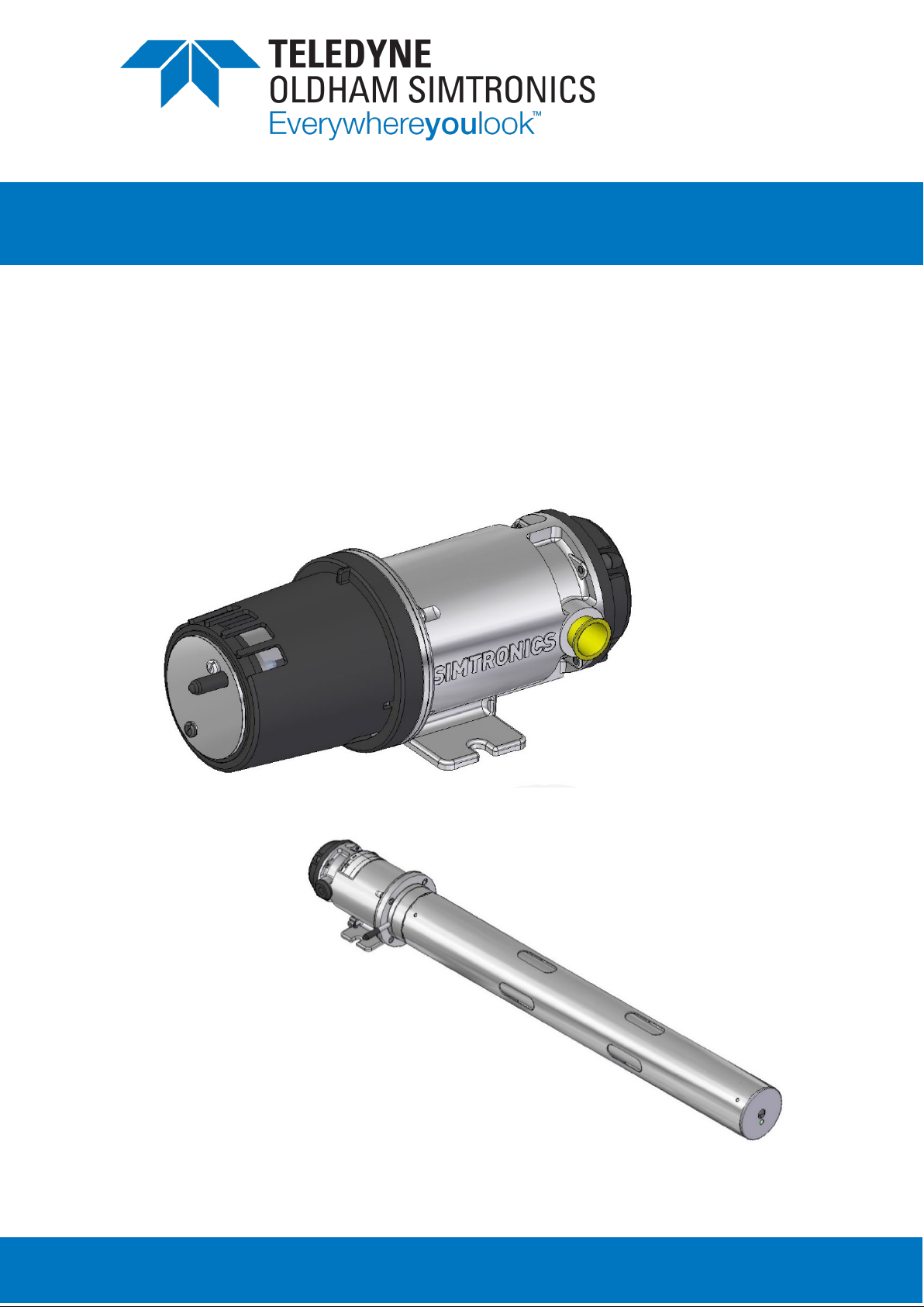
GD10-P00 and GD10-PE0
INFRARED POINT GAS DETECTOR
O
PERATING
M
ANUAL

GD10-P00 and GD10-PE0
INFRARED POINT GAS DETECTOR
OPERATING MANUAL
II
850-811250
Revision 13b
User Manuals in other languages are available on
Website https://teledynegasandflamedetection.com
Copyright June 2021 by TELEDYNE OLDHAM SIMTRONICS S.A.S.
All rights reserved. No reproduction of all or part of this document, in any form, is permitted
without the written consent of TELEDYNE OLDHAM SIMTRONICS S.A.S .
All of the information that is provided in this document is accurate to the best of our knowledge.
As a result of continuous research and development, the specifications of this product may be
changed without prior notice.
English version is the original version
TELEDYNE OLDHAM SIMTRONICS S.A.S.
Rue Orfila
Z.I. Est – CS 20417
62027 ARRAS Cedex

GD10P00 and GD10PE
INFRARED POINT GAS DETECTOR
OPERATING MANUAL
850-811250
Revision 13b
III
Thank you for choosing this TELEDYNE OLDHAM SIMTRONICS instrument.
All the necessary actions have been taken in order to ensure your complete satisfaction with this
equipment.
It is important that you read this entire manual carefully and thoroughly.
Limitation of Liability
The Company TELEDYNE OLDHAM SIMTRONICS S.A.S., hereinafter referred to as “TELEDYNE
OLDHAM SIMTRONICS” throughout this document, shall not be held responsible for any
damage to the equipment or for any physical injury or death resulting in whole or in part from the
inappropriate use or installation of the equipment, non-compliance with any and all instructions,
warnings, standards and/or regulations in force.
No business, person or legal entity may assume responsibility on behalf of TELEDYNE OLDHAM
SIMTRONICS, even though they may be involved in the sale of TELEDYNE OLDHAM
SIMTRONICS products.
TELEDYNE OLDHAM SIMTRONICS shall not be responsible for any direct or indirect damage,
or any direct or indirect consequence, resulting from the sale and use of any of its products
UNLESS SUCH PRODUCTS HAVE BEEN SELECTED BY TELEDYNE OLDHAM SIMTRONICS
ACCORDING TO THE APPLICATION.
Ownership clauses
The drawings, specifications, and information herein contain confidential information that is the
property of TELEDYNE OLDHAM SIMTRONICS.
This information shall not, either in whole or in part, by physical, electronic, or any other means
whatsoever, be reproduced, copied, divulged, translated, or used as the basis for the
manufacture or sale of TELEDYNE OLDHAM SIMTRONICS equipment, or for any other reason
without the prior consent of TELEDYNE OLDHAM SIMTRONICS.
Warning
This is not a contractual document. In the best interest of its customers and with the aim of
improving performance, TELEDYNE OLDHAM SIMTRONICS reserves the right to alter the
technical features of its equipment without prior notice.
READ THESE INSTRUCTIONS CAREFULLY BEFORE THE FIRST USAGE: these instructions
should be read by all persons who have or will have responsibility for the use, maintenance, or
repair of the instrument.
This instrument shall only be deemed to be in conformance with the published performance if
used, maintained, and repaired in accordance with the instructions of TELEDYNE OLDHAM
SIMTRONICS by TELEDYNE OLDHAM SIMTRONICS personnel or by personnel authorized by
TELEDYNE OLDHAM SIMTRONICS.

GD10-P00 and GD10-PE0
INFRARED POINT GAS DETECTOR
OPERATING MANUAL
IV
850-811250
Revision 13b
Important Information
The modification of the material and the use of parts of an unspecified origin shall entail the
cancellation of any form of warranty.
The use of the unit has been projected for the applications specified in the technical
characteristics. Exceeding the indicated values cannot in any case be authorized.
TELEDYNE OLDHAM SIMTRONICS recommends regular testing of fixed gas detection installations
(read Chapter 7).
Before any intervention on the detector, please refer to IEC 60079-29-2 standard.
Warranty
Under normal conditions of use and on return to the factory, parts and workmanship are
guaranteed for 5 years, IR sources are guaranteed for 15 years.
Waste Electrical and Electronic Equipment (WEEE
directive)
European Union (and EEA) only. This symbol indicates that, in conformity with directive
DEEE (2002/96/CE) and according to local regulations, this product may not be
discarded together with household waste.
It must be disposed of in a collection area that is set aside for this purpose, for example at a site
that is officially designated for the recycling of electrical and electronic equipment (EEE) or a
point of exchange for authorized products in the event of the acquisition of a new product of the
same type as before.

GD10P00 and GD10PE
INFRARED POINT GAS DETECTOR
OPERATING MANUAL
850-811250
Revision 13b
V
Table of Contents
1Product description .....................................................................1
1.1 GD10P Description .........................................................................................1
1.2 GD10PE Description.......................................................................................3
2GD10P Technical specifications................................................5
3GD10PE Technical specifications..............................................9
4Installation .....................................................................................13
4.1 Positioning ........................................................................................................13
4.2 GD10P Fixing....................................................................................................14
4.3 GD10P Weather Protection ........................................................................14
4.4 GD10P Duct or pipe mounting..................................................................15
4.5 GD10PE Fixing..................................................................................................17
4.6 GD10PE Weather protection/standalone mounting..........................17
4.7 GD10PE Duct or pipe mounting................................................................17
4.8 External cable .................................................................................................19
4.9 Electrical connection....................................................................................20
5Commissioning.............................................................................21
5.1 Visual inspection.............................................................................................21
5.2 Power up ..........................................................................................................21
5.3 Checking system functions.........................................................................22
6Operation ......................................................................................23
6.1 Analog Output Protocol..............................................................................23
6.2 HART® Interface .............................................................................................24
7Maintenance.................................................................................29
7.1 Cleaning of optical lens/mirror..................................................................29
7.2 Function test.....................................................................................................29
7.3 Calibration test................................................................................................30
7.4 Re-zero...............................................................................................................33
7.5 Fault finding .....................................................................................................34

GD10-P00 and GD10-PE0
INFRARED POINT GAS DETECTOR
OPERATING MANUAL
VI
850-811250
Revision 13b
8Specific instructions for use in explosive atmospheres and
operational safety ........................................................................35
9Marking ..........................................................................................37
10 Declarations of conformity .........................................................39
11 Product coding.............................................................................43
11.1 GD10P Gas and range code.....................................................................45
12 Accessories and spare parts .....................................................47
12.1 GD10P Accessories ........................................................................................47
12.2 GD10PE Accessories ......................................................................................48
12.3 Spares................................................................................................................48

GD10P00 and GD10PE
INFRARED POINT GAS DETECTOR
OPERATING MANUAL
850-811250
Revision 13b
1
1Product description
Compared with catalytic sensors, the GD10P and GD10PE has the following advantages:
•Presence of oxygen is not required for correct measurement, which makes the GD10P/PE
suitable even in an inert gas atmosphere.
•No possibility of poisoning of the detector since no chemical reaction occurs, i.e. silicon
vapors and H2S have no effect on the detector or the measurement.
•The gas flow rate has no influence on accuracy.
•There are no saturation effects which could lead to false measurements. Thus, the detector
is capable of measuring gas concentrations up to 100% vol.
•The detector has a continuous self-test function, and reports dirty optics and fault
conditions to the control system.
•Total system costs can be dramatically reduced with the GD10P/PE:
•High reliability results in low test frequency and no calibration costs.
GD10P and GD10PE are sensitive to absorption bands related to carbon - hydrogen bonds.
As a result, all molecules with this type of bond are susceptible to detection. The intensity of this
absorption line is, however, significantly dependent on the molecule under consideration.
In general, the larger the molecule is, the greater the absorption strength will be, and so the better
it is detected.
There is therefore some measurement interference between hydrocarbon vapor compounds since
their absorption bands share some spectral regions.
The level of interference depends on the relative position of these absorption bands, relative to
the working range of the interference filter.
1.1 GD10P Description
The GD10P has been designed with features that provide an effective response to the detection
of gas hazards in a wide range of industrial environments from boiler plant rooms to offshore
petrochemical installations.
These infrared gas detectors differ from all other models, because they use solid-state infrared
sources. The complete opto-mechanical design and construction is so stable that an ultra-fast
speed of response can be achieved whilst providing unparalleled service life and detector
stability, thus saving on maintenance and service costs.
We offer the longest combined detector and IR source warranty on the market.
Supplied with worldwide performance (CSA / IECEx / ATEX / INMETRO) and hazardous area
approvals.

GD10-P00 and GD10-PE0
INFRARED POINT GAS DETECTOR
OPERATING MANUAL
2
850-811250
Revision 13b
Suitable for use in SIL 2 and SIL 3 systems.

GD10P00 and GD10PE
INFRARED POINT GAS DETECTOR
OPERATING MANUAL
850-811250
Revision 13b
3
1.2 GD10PE Description
The GD10PE is designed for critical applications involving large volumes of air with high velocity.
Places where you need fast reliable detection of low gas concentrations. GD10PE is in a class of
its own.
These infrared gas detectors differ from all other models, because they utilise silicon based solid-
state infrared sources. The complete opto mechanical design and construction is so stable that an
ultra-fast speed of response can be achieved whilst providing unparalleled service life and
detector stability, thus saving on maintenance and service costs.
We offer the longest combined detector and IR source warranty on the market.
Typical critical applications include the monitoring of air intakes for HVAC systems in living
quarters or generators, and monitoring for potential gas leakages in areas with high temperatures
in gas turbine packages.
The GD10PE is a stable instrument, and with a measuring range of 0 – 20%LEL the sensitivity for
the GD10PE is 5 times higher than standard point detectors.
The GD10PE is designed for installation in air ducts and for mounting through walls and
bulkheads in places such as pump rooms, but may also be used as a standalone point detector
in places where the properties of the GD10PE is required, such as low ppm level detection.
A weather protection accessory is used for exposed detector installations.
•Duct mounted close to the intake.
•Directly mounted on an air intake.
•General outdoor locations.
The detection concept is based on the measurement of infrared radiation passing through a
volume of gas.
Solid state IR-source
The silicon-based IR-source used in the GD10PE is insensitive to shock and vibration, and does
not need to be replaced during the detector service life.
No false gas alarms
A false alarm, resulting in a production shutdown is extremely expensive. The dual wavelength,
dual path concept, together with the electronic design, guarantees that there are no false gas
alarms.
No field recalibration
Field recalibration of gas detectors is time consuming (cost) and introduces a risk of mistakes
(safety). The GD10PE stays within the specifications for its service lifetime without recalibration.
The response time is among the fastest on the market, giving real world figures. We measure the
response from the actual gas release, taking delays of the weather protection, initial detection,
etc. into account. Trip levels down to 4%LEL combined with a response time in the range of 1
second (option) should cover even the most demanding requirements.

GD10-P00 and GD10-PE0
INFRARED POINT GAS DETECTOR
OPERATING MANUAL
4
850-811250
Revision 13b

GD10P00 and GD10PE
INFRARED POINT GAS DETECTOR
OPERATING MANUAL
850-811250
Revision 13b
5
2GD10P Technical specifications
Version: 0-100%LEL Methane, 5 sec. response time.
(Specification for other types on request)
GENERAL
Detection method IR-absorption, dual wavelength, dual path
IR-Source Solid state IR source, 32Hz flash
Gases detected ( 1) Detector versions for several hydrocarbons as well as CO2.
Self-test Continuous
Calibration Factory set, no field recalibration
PERFORMANCE
Lifetime stability ±5% of full scale (FS) reading
Accuracy ±3% FS between 0-50 % reading
±5% FS between 50-100 % reading
Response time ( 2) T20 = 0.8 sec.(Optional 0.2 sec)
T50 = 2.1 sec.(Optional 0.4 sec)
T90 = 5 sec.(Optional 1.0 sec)
Start-up time Less than 60 sec3., full specification obtained after 30 min. warmup
time
1
The detector is intended to measure the gas for which it is indicated
2
In natural diffusion and without the weather protection. The response time does not depend on the gas. This response time is
available on any of the outputs of the device and is determined by the time of response of all parts of equipment within the gas
detection system.
3
Sometimes, under very specific conditions, start-up can be longer. Please refer to 5.2 for additional details

GD10-P00 and GD10-PE0
INFRARED POINT GAS DETECTOR
OPERATING MANUAL
6
850-811250
Revision 13b
DETECTOR WARNINGS
Early Dirty Optics 55% signal attenuation
Dirty Optics 70% signal attenuation
Detector failure Main function fault or blocked optics.
Output signal
Standard Current source 4 – 20 mA, max. load impedance 500 Ohm
Option Current sink 4 – 20 mA
Maintenance HART® interface
ELECTRICAL
Power supply 24 VDC, range 18-32 VDC
Power consumption Approx. 3.5 W
Connection 3 wires (0.5mm2- 1.5mm2)
Cable entry M20 Ex e cable gland
ENVIRONNEMENT
Storage Temperature: -40°C to + 70°C (-40°F to +158°F)
Duration: 2 years in clean atmosphere
Pressure: 1013 hPa +/- 20%
Humidity: 100% RH uncondensed
Operating -40°C to + 60°C (-40°F to +140°F)( 4)
Humidity (operation) 100% RH uncondensed
Pressure (operation) 1013 hPa +/- 10%( 5)
4Temperature limits for explosion protection and performance
5
Pressure limits for explosion protection and performance

GD10P00 and GD10PE
INFRARED POINT GAS DETECTOR
OPERATING MANUAL
850-811250
Revision 13b
7
HOUSING
Main compartment Ex db IIC T6 Gb
Terminal compartment Ex eb
Protection category IP66/IP67 EN/IEC 60529 and ABNT NBR IEC 60529 ( 6)
Housing material Stainless steel SIS2343 (ASTM 316)
Weight Approx. 2.9 kg (6.4 Lbs)
Dimensions 264L x 104W x 106H (mm) - 10.4 x 4.1 x 4.2 (inches)
EMC
Compliant to EN 50270 and IEC 61326-3-1 7
WARRANTY
5 years full warranty on complete instrument
15 years warranty on the IR-sources
6IP ratings does not mean that the equipment will detect gas during or after exposure to the defined conditions. It is also
recommended to use the weather protection.
7
When GD10P is not directly connected to AC or DC power supply network

GD10-P00 and GD10-PE0
INFRARED POINT GAS DETECTOR
OPERATING MANUAL
8
850-811250
Revision 13b

GD10P00 and GD10PE
INFRARED POINT GAS DETECTOR
OPERATING MANUAL
850-811250
Revision 13b
9
3GD10PE Technical specifications
GENERAL
Detection method IR-absorption, dual wavelength, dual path
IR-Source Solid state IR source, 32 Hz flash
Detection range 0-20% LEL (0-1% Vol.) methane
Gases detected ( 8) Hydrocarbons
Self-test Continuous
Calibration Factory set, no field recalibration
PERFORMANCE
Lifetime stability ±1.4%LEL
Accuracy ±1%LEL (0-10 % LEL reading)
±1.4%LEL (10-20 %LEL reading)
Response time ( 9) T20 = 0.8 sec.
T50 = 2.1 sec.
T90 = 5 sec.
Start-up time Less than 60 sec10., full specification obtained after 30 min. warmup
time
8
The detector is intended to measure the gas for which it is indicated
9
In natural diffusion and without the weather protection. The response time does not depend on the gas. This response time is
available on any of the outputs of the device and is determined by the time of response of all parts of equipment within the gas
detection system.
10
Sometimes, under very specific conditions, start-up can be longer. Please refer to 5.2 for additional details

GD10-P00 and GD10-PE0
INFRARED POINT GAS DETECTOR
OPERATING MANUAL
10
850-811250
Revision 13b
DETECTOR WARNINGS
Early Dirty Optics 55% signal attenuation
Dirty Optics 70% signal attenuation
Option: Dirt accumulation (2mA)
Detector failure Main function fault or blocked optics
OUTPUT SIGNAL
Standard Current source 4 – 20 mA, max. load impedance 500 Ohm
Option Current sink 4 – 20 mA
Maintenance HART® interface
ELECTRICAL
Power supply 24 V DC, range18-32 V DC
Power consumption Approx. 3.5 W
Connection 3 wires (0.5mm2- 1.5mm2)
Cable entry M20 Ex e cable gland
ENVIRONNEMENT
Storage Temperature: -40°C to + 70°C (-40°F to +158°F)
Duration: 2 years in clean atmosphere
Pressure: 1013 hPa +/- 20%
Humidity: 100% RH uncondensed
Operating -40°C to + 60°C (-40°F to +140°F)(11)
Humidity (operation) 100% RH uncondensed
Pressure (operation) 1013 hPa +/-10%(12)
11 Temperature limits for explosion protection and performance
12 Pressure limits for explosion protection and performance

GD10P00 and GD10PE
INFRARED POINT GAS DETECTOR
OPERATING MANUAL
850-811250
Revision 13b
11
EXPLOSION PROOF HOUSING
Main compartment Ex db IIC T6 Gb
Terminal compartment Ex eb
Protection category IP66/IP67 EN/IEC 60529 and ABNT NBR IEC 60529(13)
Housing material Stainless steel SIS2343 (ASTM 316)
Weight Approx. 6.5 kg
Dimensions 805L x 104W x 106H (mm)
EMC
Compliant to EN 50270 and IEC 61326-3-1 14
WARRANTY
5 years full warranty on complete instrument
15 years warranty on the IR-sources
13 IP ratings does not mean that the equipment will detect gas during or after exposure to the defined conditions. It is also
recommended to use the weather protection.
14
When GD10PE is not directly connected to AC or DC power supply network

GD10-P00 and GD10-PE0
INFRARED POINT GAS DETECTOR
OPERATING MANUAL
12
850-811250
Revision 13b

GD10P00 and GD10PE
INFRARED POINT GAS DETECTOR
OPERATING MANUAL
850-811250
Revision 13b
13
4Installation
Installation shall be in accordance with the standards in force, classification of
the zone, and in conformity with standard EN/IEC 60079-14, the editions in
force, or with other national and/or local standards.
4.1 Positioning
Both GD10P and GD10PE detectors should be mounted where gas leakage is most likely to
occur. To detect methane, which is lighter than air, inside an enclosed area the detector should
be mounted high in the area to be protected or immediately above potential leakage sites.
To detect gases heavier than air, e.g. propane, the detector should be mounted below the
potential leakage site.
The detector should be mounted in a place where maintenance, i.e. cleaning of the optics, is
easily performed.
The detector may be mounted in areas where no oxygen is present.
The detector may be mounted in areas with strong airflow
The detector can be mounted where it could be drenched by water.
However, immersion has its limits. It assumes that the cable glands have been correctly mounted.
Furthermore, the detector will trigger an optical fault. After immersion, the detector will require
cleaning because of the possible traces caused by immersion on the optical parts.
Finally, it is also important to check that the gas inlet tube is properly covered so that there is
nothing getting inside.
Please note that the 4 holes in each end of the GD10PE weather protection are for water
drainage, and should not be blocked.
Air velocity limits: none 15
15
Taking into account the principle of detection, a pressure variation will proportionally influence the measurement compared to
the calibration one (1013HPa).

GD10-P00 and GD10-PE0
INFRARED POINT GAS DETECTOR
OPERATING MANUAL
14
850-811250
Revision 13b
4.2 GD10P Fixing
The detector is mounted by means of a projecting mounting leg using two M8 screws and
washers, or by means of the Duct Mounting Flange Kit (4 x M8 screws). The detector should
preferably be mounted so that the longitudinal axis of the detector is horizontal. This will prevent
accumulation of water and dust on the optics. The Weather Protection must always be oriented
correctly for optimal performance.
Figure 1: GD10P mounting
4.3 GD10P Weather Protection
When the GD10P is mounted outdoors, the flow direction indicator must poin t
upwards
See “Flow Direction Indicator” in Figure 2 below. Orientation of the Weather Protection is
performed as follows:
•Use a screwdriver to loosen the two screws on the Weather Protection
•Rotate the Weather Protection to correct position
•Tighten the screw with a torque of max. 0.5 Nm
M8 screw
Weather Protection
This manual suits for next models
4
Table of contents
Other TELEDYNE OLDHAM SIMTRONICS Gas Detector manuals

TELEDYNE OLDHAM SIMTRONICS
TELEDYNE OLDHAM SIMTRONICS OLC 10 User manual

TELEDYNE OLDHAM SIMTRONICS
TELEDYNE OLDHAM SIMTRONICS OLC User manual

TELEDYNE OLDHAM SIMTRONICS
TELEDYNE OLDHAM SIMTRONICS CTX 300 User manual

TELEDYNE OLDHAM SIMTRONICS
TELEDYNE OLDHAM SIMTRONICS iTRANS 2 User manual

TELEDYNE OLDHAM SIMTRONICS
TELEDYNE OLDHAM SIMTRONICS OLCT 80 d User manual


