TELEDYNE OLDHAM SIMTRONICS OLC User manual

NPO100GB-Rev.M.1
OLC/OLCT100
GAS DETECTOR
USER
MANUAL

OLC/OLCT100
GAS DETECTOR
USER MANUAL
II
NPO100GB
Rev.M.1
User Manuals in other languages are available on
Website https://teledynegasandflamedetection.com
Copyright March 2021 by TELEDYNE OLDHAM SIMTRONICS S.A.S.
All rights reserved. No reproduction of all or part of this document, in any form, is permitted
without the written consent of TELEDYNE OLDHAM SIMTRONICS S.A.S.
All of the information that is provided in this document is accurate to the best of our knowledge.
As a result of continuous research and development, the specifications of this product may be
changed without prior notice.
TELEDYNE OLDHAM SIMTRONICS S.A.S.
Rue Orfila
Z.I. Est – CS 20417
62027 ARRAS Cedex

OLC/OLCT100
GAS DETECTOR
USER MANUAL
NPO100GB
Revision M.1
III
Thank you for choosing this TELEDYNE OLDHAM SIMTRONICS instrument.
All of the necessary actions have been taken in order to ensure your complete satisfaction with
this equipment.
It is important that you read this entire manual carefully and thoroughly.
The extent of our responsibility
●The company TELEDYNE OLDHAM SIMTRONICS S.A.S.,hereinafter referred to as TELEDYNE
OLDHAM SIMTRONICS throughout this document, shall not be held responsible for any damage
to the equipment or for any physical injury or death resulting in whole or in part from the
inappropriate use, installation, or storage of the equipment, which is the result of not complying
with the instructions and warnings, and/or with the standards and regulations in force.
TELEDYNE OLDHAM SIMTRONICS does not support or authorise any business, person, or legal
entity in assuming responsibility on behalf of TELEDYNE OLDHAM SIMTRONICS, even though
they may be involved in the sale of TELEDYNE OLDHAM SIMTRONICS products.
TELEDYNE OLDHAM SIMTRONICS shall not be responsible for any damage, direct or indirect,
or for damages and interest, direct or indirect, resulting from the sale and use of any of its products
UNLESS SUCH PRODUCTS HAVE BEEN DEFINED AND CHOSEN BY TELEDYNE OLDHAM
SIMTRONICS FOR THE USE THAT THEY ARE INTENDED.
Ownership clauses
●The drawings, specifications, and information herein contain confidential information that is the
property of TELEDYNE OLDHAM SIMTRONICS.
●This information shall not, either in whole or in part, by physical, electronic, or any other means
whatsoever, be reproduced, copied, divulged, translated, or used as the basis for the
manufacture or sale of TELEDYNE OLDHAM SIMTRONICS equipment, or for any other reason
without the prior consent of TELEDYNE OLDHAM SIMTRONICS.
Warning
This is not a contractual document. In the best interest of its customers and with the aim of
improving performance, TELEDYNE OLDHAM SIMTRONICS reserves the right to alter the
technical features of its equipment without prior notice.
READ THESE INSTRUCTIONS CAREFULLY BEFORE THE FIRST USAGE: these instructions
should be read by all persons who have or will have responsibility for the use, maintenance, or
repair of the instrument.
This instrument shall only be deemed to be in conformance with the published performance if
used, maintained, and repaired in accordance with the instructions of TELEDYNE OLDHAM
SIMTRONICS by TELEDYNE OLDHAM SIMTRONICS personnel or by personnel authorised by
TELEDYNE OLDHAM SIMTRONICS.

OLC/OLCT100
GAS DETECTOR
USER MANUAL
IV
NPO100GB
Revision M.1
Important Information
The modification of the material and the use of parts of an unspecified origin shall entail the
cancellation of any form of warranty.
The use of the unit has been projected for the applications specified in the technical
characteristics. Exceeding the indicated values cannot in any case be authorized.
Catalytic sensors are susceptible to poisoning by traces of several substances. This leads to an
inhibition which can be permanent or temporary depending on the contaminant, the
concentration of the contaminant, the duration of exposure to the contaminant.
Poisoning may result from exposure to substances as:
•Silicones (e.g. Waterproofing, adhesives, release agents, special oils and greases,
certain medical products, commercial cleaning agents)
•Tetraethyl lead (e.g. Leaded petrol, particularly aviation petrol ‘avgas’)
•Sulfur compounds (sulfur dioxide, hydrogen sulfide)
•Halogenated compounds (r134a, hfo, etc.)
•Organo-phosphorus compounds (e.g. Herbicides, insecticides, and phosphate esters in
fireproof hydraulic fluids
TELEDYNE OLDHAM SIMTRONICS recommends regular testing of fixed gas detection
installations (read Chapter 5).
Guarantee
Under normal conditions of use and on return to the factory, parts and workmanship are
guaranteed for 3 years, excluding such consumables as sensors, filters, etc.
Destruction of the equipment
European Union (and EEA) only. This symbol indicates that, in conformity with
directive DEEE (2002/96/CE) and according to local regulations, this product may
not be discarded together with household waste.
It must be disposed of in a collection area that is set aside for this purpose, for example at a site
that is officially designated for the recycling of electrical and electronic equipment (EEE) or a
point of exchange for authorized products in the event of the acquisition of a new product of the
same type as before.

OLC/OLCT100
GAS DETECTOR
USER MANUAL
NPO100GB
Revision M.1
V
Table of Contents
1Presentation...................................................................................... 1
1.1 Purpose..................................................................................................................1
1.2 Operating principle ..........................................................................................1
1.3 Composition of the detector........................................................................1
1.4Internal elements...............................................................................................2
1.5 Identifiers...............................................................................................................3
2Ranges............................................................................................... 5
2.1 OLC 100 and OLCT 100 ranges ....................................................................5
3Installation ........................................................................................ 6
3.1 Regulations and conditions of use .............................................................6
3.2 Necessary equipment .....................................................................................6
3.3 Electrical power supply...................................................................................7
3.4 Location of the detector................................................................................7
3.5 Detector positioning.........................................................................................7
3.6 Connector cable...............................................................................................8
3.7 Cable connection ............................................................................................10
4Calibration........................................................................................ 13
4.1 Necessary equipment .....................................................................................13
4.2 Commissioning ...................................................................................................13
4.3 Stabilization time................................................................................................14
4.4 Calibrating the OLC 100 .................................................................................14
4.5 Calibrating the OLCT 100 ...............................................................................15
5Preventive maintenance .............................................................. 21
5.1 Frequency of maintenance..........................................................................21
5.2 Actions ...................................................................................................................22
6Maintenance ................................................................................... 23

OLC/OLCT100
GAS DETECTOR
USER MANUAL
VI
NPO100GB
Revision M.1
6.1 Opening the cover ...........................................................................................23
6.2 Checking the current generator.................................................................24
6.3 Possible errors ......................................................................................................25
6.4 Replacing sensor block...................................................................................26
7Accessories ...................................................................................... 29
7.1 Cable gland ........................................................................................................32
8Spare parts ....................................................................................... 33
9Declarations of EU conformity..................................................... 35
10 Technical specifications ............................................................... 41
10.1 Dimensional characteristics ..........................................................................41
10.2 General Specifications....................................................................................42
10.3 Catalytic sensor (OLCT 100 XP)....................................................................43
10.4 Toxic sensors (OLCT 100 XP and OLCT 100 IS).........................................44
10.5 Semiconductor sensors (OLCT 100 XP)......................................................47
10.6 Infrared sensors (OLCT 100 XP-IR) ................................................................48
12 Specific instructions for use in explosive atmospheres and
operational safety .......................................................................... 51
12.1 General comments ..........................................................................................51
12.2 Cable Entries .......................................................................................................51
12.3 Threaded joints...................................................................................................52
12.4 Electrostatic Hazard .........................................................................................52
12.5 Metrological performance for the detection of flammable gases
52
12.6 Scope of use........................................................................................................53
12.7 Functional safety ...............................................................................................53
12.8 Reliability data....................................................................................................54
12.9 Special conditions of use ...............................................................................54
13 Appendix | Ordering information............................................ 55
13.1 Gas List...................................................................................................................55

OLC/OLCT100
GAS DETECTOR
USER MANUAL
NPO100GB
Revision M.1
1
1Presentation
1.1 Purpose
This range of sensors is designed to detect a particular gas depending on the type of sensor used.
1.2 Operating principle
The measurement sensor converts the target gas into voltage or current. This electrical parameter
is:
•Either conducted directly via a connecting cable to a dedicated central measurement unit
(as with the OLC 100 explosimeter) that operates on the principle of the Wheatstone
bridge. Such a measurement unit is available in the TELEDYNE OLDHAM SIMTRONICS
range.
•Or amplified, corrected for temperature, linearised, and converted to a 4-20 ma signal
(as for the OLCT 100) and conducted via a connecting cable to a centralized unit
(measurement unit or industrial automation system).
1.3 Composition of the detector
A detector comprises the following elements:
Id.
Description
1. Company label
2. Cover
3.
PCB protector (for OLCT version).
4.
PCB.
5.
Cable gland inlet. (cable gland not supplied).
6. Enclosure.
7. Sensor block.
8. Nozzle.
9. Ground connection.
10. LEL sensor (high temperature).

OLC/OLCT100
GAS DETECTOR
USER MANUAL
2
NPO100GB
Revision M.1
Figure 1 : component parts of an OLCT 100 detector
1.4 Internal elements
The following elements are internally accessible to the user:
Id.
Description
1. Terminal for the cable being connected to the controller (measurement unit, automation).
2. Sensor block connector.
3. Calibration ribbon connector.
4.
4 mA adjustment.
5.
Push button access for 4 mA adjustment.
6.
Zeroing.
7. Sensitivity adjustment.
OLC 100 detector
OLCT 100 explosimeter
OLCT 100 detector for toxic gases
Figure 2 : internal view of the detectors

OLC/OLCT100
GAS DETECTOR
USER MANUAL
NPO100GB
Revision M.1
3
1.5 Identifiers
The enclosure has two identifier labels, as described below:
1.5.1 Company label
This in turn groups the detector features together:
Id.
Description
Figure 3 : Firmplate (example)
1. Manufacturer's name
2. Name of product
3. ATEX Marking
4.
CE symbol and the number of the organisation that
provided the TELEDYNE OLDHAM SIMTRONICS
production quality certification (INERIS )
5. Warning
6. Type of gas detected and range of measurement
7. Temperature range for which the detector is certified for
use in explosive areas
(excluding metrological
performance)
8.
Symbol of Marine Certification and number of the
Approval Agency that issued the certificate
9. Recycling symbol
10. Additional markings ATEX, IECEX, INMETRO, etc and
numbers of certificates
1.5.2 Side label
This label shows the following :
Id.
Description
1. Thread diameter and pitch for cable inlet
2. Detector reference number, less sensor (P/N)
3. Detector serial number (S/N)
The first two digits (in this case 09) correspond to the year of
manufacture (in this case 2009)
Figure 4 : side label
2
3
1

OLC/OLCT100
GAS DETECTOR
USER MANUAL
4
NPO100GB
Revision M.1

OLC/OLCT100
GAS DETECTOR
USER MANUAL
NPO100GB
Revision M.1
5
2Ranges
2.1 OLC 100 and OLCT 100 ranges
The OLC 100 range is reserved for the detection of explosive vapor by using a Wheatstone
bridge sensor.
The OLCT 100 range of detectors is provided with an amplifier producing a 2 or 3 wire 4-20
mA analog output. These are transmitter detectors and, therefore, the letter "T".
OLC 100
OLCT 100 XP
OLCT 100
XPIR
OLCT 100 IS
OLCT 100 HT
Features Explosion
proof Explosionproof Explosionproof Intrinsically
safe (1)
Explosionproof
(2)
Detection of
explosive
gases
Catalytic
sensor (VQ1)
Catalytic
sensor (VQ1 or
AP 4F) or semi-
conductor
Catalytic
sensor
high
temperature
Detection of
toxic gases
EC
Or SC Infrared sensor EC
Detection of
oxygen EC EC
Detection of
CO2Infrared sensor
4-
20 mA
output (3)
2 wires for EC
3 wires for SC
3 wires for LEL
3 wires 2 wires 3 wires
(1) Requires the use of a Zener barrier
(2) Sensor can be remote up to 5, 10, or 15 meters using a high temperature cable
(3) mV bridge output, 3 wires
EC : Electrochemical sensor
SC : Semi-conductor sensor.
LEL : Catalytic bead
AP : Poison resistant
Table 1 : comparison of OLC 100 and OLCT 100 series detectors

OLC/OLCT100
GAS DETECTOR
USER MANUAL
6
NPO100GB
Revision M.1
3Installation
It is recommended that the guides relating to the installation, use, and maintenance of
flammable gas and oxygen detectors (standard EN/IEC 60079-29-2) and toxic gas
detectors (standard EN 45544-4) should be clearly understood.
Installation shall be in accordance with the standards in force, classification of the zone,
and in conformity with standards EN/IEC 60079-14 and EN/IEC 61241-
14, the
editions in force, or with other national and/or local standards.
3.1 Regulations and conditions of use
•The installation should meet all the regulations currently in force for installations in
explosive atmospheres, in particular the standards IEC/EN 60079-14 and IEC/EN
60079-17 (whichever editions are in force) or in accordance with other national
standards.
•Generally speaking, the ambient temperature, supply voltage, and power that are
mentioned in this document relate to explosion safety. This has nothing to do with the
operating temperatures of the detector.
•The equipment is allowed in zones 0, 1, 2, 20, 21 and 22 for ambient temperatures
ranging from -40 ° C to + 70 °.
•The detector sensor in the transmitter should always be in contact with the ambient air.
Therefore:
- Do not cover the detector.
- Do not paint the detector.
- Avoid dust.
3.2 Necessary equipment
•Complete detector assembly
•Requisite connector cable
•Multimeter (intrinsically safe, if necessary)
•Tools
•Fixing hardware

OLC/OLCT100
GAS DETECTOR
USER MANUAL
NPO100GB
Revision M.1
7
3.3 Electrical power supply
Type of detector
Supply (V DC)
Maximum current
(mA)
Power consumed
(mW)
OLCT 100 XP HT 15,5 to 32 110 1705
OLCT 100 XP LEL 15,5 to 32 100 1550
OLCT 100 XPIR 15,5 to 32 80 930
OLCT 100 XP EC
11 to 32
23,5
260
OLCT 100 IS EC
11 to 32
23,5
260
OLCT 100 XP SC
15,5 to 32
100
1550
OLC 100 (VQ1)
By TELEDYNE OLDHAM
SIMTRONICS controller 340 (1)
OLC 100 (4F)
By TELEDYNE OLDHAM
SIMTRONICS controller 370 (1)
(1) Depends on the gas controller
3.4 Location of the detector
Depending on the density of the gas to be detected or the application, the detector shall be
positioned at the ground level, or on the ceiling at the same height as the airflow, or near to the
air extraction ducts. Heavy gases may be detected at the ground level, while light gases will be
found at ceiling height. Gas densities are provided on page 28.
3.5 Detector positioning
The detector shall be installed with the detector sensor pointing downwards.
Any tilt of more than 45° from the vertical will lead to an inaccurate measurement.
Figure 5 : sensor pointing downwards and maximum tilt angle
OLC/OLCT100
GAS DETECTOR
USER MANUAL
8
NPO100GB
Revision M.1
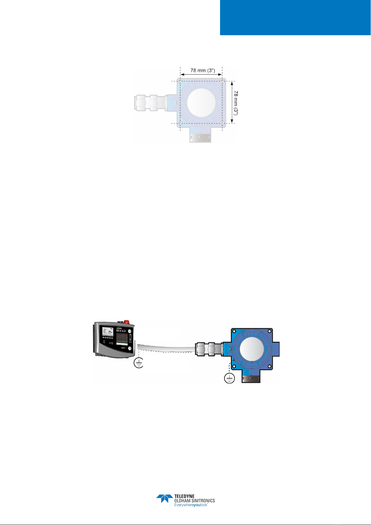
Installation of the enclosure shall be secured with 4 x M6 screws and the appropriate plugs for
the supporting material
Figure 6 : fixing template for the enclosure
A special holder is available for mounting the detector on the ceiling (see section on accessories.
In the OLCT 100 HT version, only the removable detector head can be used at temperatures from
-20°C to + 200°C. The OLCT 100 HT enclosure can only be used in ambient temperatures from
-40°C to + 70°C. The high temperature cable between the OLCT 100 HT enclosure and the
head is integral with the instrument and is not user-replaceable.
The cable should be protected mechanically
3.6 Connector cable
The detector shall be connected to the controller (measurement and automation unit) by a
shielded instrumentation cable, armoured when necessary. The choice of cable will be dictated
by the particular requirements of the installation, distance, and type of detector (see table below).
Figure 7: the cable connecting the detector to the controller should be chosen with care
Central unit
Detector
Connector cable

OLC/OLCT100
GAS DETECTOR
USER MANUAL
NPO100GB
Revision M.1
9
Type of detector
Type of sensor
Maximum length (km) for cable
of cross-section as indicated
Maximum load
resistance for 4-
20 Ma
0,5 m m²
0,9 m m²
1,5 m m²
Upstream line voltage
(Vcc)
24 24 24
OLCT 100 XP
Catalytic or
semiconductor
0,8
1,4
2,4
250
OLCT 100 XP (1) Electrochemical <4 <4 <4
OLCT 100 XPIR
Infra-red
1,4
2,6
4,4
250
OLCT 100 IS (2)
Electrochemical
1,8
3,3
<4
OLCT 100 HT
Catalytic, high
temperature
0,8
1,4
2,4
250
(1) for resistance calculations, the assumed load is 120
Ω
for 4-20 Ma.
(2) for resistance calculations, the assumed load is 120
Ω
for 4-20 Ma, and a 300
Zener
blocking diode.
Warning: all wiring should meet the installation standards and should be described in a system
document for SI installations.
The cable must have a braided screen to reduce the influence of electrical and radio-frequency
interference. A cable such as AFNOR M 87-202 01-IT-09-EG-FA (Nexans) may be used. It shall
be selected according to the type of detector and in accordance with the table shown
hereinabove. Below are further examples of suitable cables:
Non ATEX zone: CNOMO FRN05 VC4V5-F
ATEX zone: GEUELYON (U 1000RHC1)
ATEX zone: GVCSTV RH (U 1000)
ATEX zone: xx-xx-09/15- EG-SF or EG-FA or EG-PF (U 300 compatible with M87202)
The maximum permissible length will depend on the cross-section of the cable conductors (see
table) and on the minimum supply voltage.

OLC/OLCT100
GAS DETECTOR
USER MANUAL
10
NPO100GB
Revision M.1
3.7 Cable connection
3.7.1 Switch off line power supply
On the controller:
1. Inhibit any installation alarms to avoid unexpected triggering during operation.
2. In accordance with the manufacturer’s instructions, switch off the power to the module in order
to be connected to the detector.
3.7.2 Cable preparation
The cable shall be taken from the controller (measurement and automation) to the point of
measurement (see Figure 8). The passage, support, and protection of the cable shall be
according to best practice.
3.7.3 Cable entry
The detector is supplied without cable gland.
It is essential that the instructions provided by the manufacturer of the compression
gland are followed and the braided screen is correctly connected. M20x1.5 flamme
proof certified cable gland shall be used (see Chapter 11).
1 - Remove the gasket and the two metal washers
(Rep A) supplied with the detector.
2 - Arrange the cable as shown in the picture.
3 - Spread the braided shield as shown in the
picture.
Avoid creating "pigtails" with the braided shield
.

OLC/OLCT100
GAS DETECTOR
USER MANUAL
NPO100GB
Revision M.1
11
4 - Insert the part back into the OLC/OLCT100
and then mount the cable gland (not supplied).
3.7.4
Cable connection
The connection of the cable between the detector and controller should be made with
the power off. The site should be at equal potential
Connect the cable to the detector side before connecting the controller side.
After the wiring has been completed, connect the cable screen to the ground terminal of the
controller.
Figure 8: connection for a 2-wire 4-20 Ma detector
Figure 9: connection for an intrinsically safe, 2-wire 4-20 Ma detector with a Zener diode
Figure 10: connection for a 3-wire 4-20 Ma detector

OLC/OLCT100
GAS DETECTOR
USER MANUAL
12
NPO100GB
Revision M.1
Figure 11: connection for a 3-wire OLC 100 type detector
3.7.5 Connecting the enclosure to ground
Connect the enclosure ground terminal to earth according to the regulations. This ground
connection may, however, be taken from the terminal on the screw fixing the PCB to the inside of
the housing.
Figure 12 : Ground connection terminal
3.7.6 Closing the cover
Before connecting the cable to the terminal on the controller, it is essential that the cover is
completely closed.
In order to lock the cover by rotation, unscrew the blocking screw until into contact
with the cover.
If you were to remove the cover, tighten the blocking screw before unscrewing the
cover.
Cover blocking
screw

OLC/OLCT100
GAS DETECTOR
USER MANUAL
NPO100GB
Revision M.1
13
4Calibration
The tasks described in this chapter are reserved for authorised trained personnel
only, since these tasks are liable to affect detection reliability
This procedure describes:
•Zero adjustment;
•Sensitivity adjustment.
4.1 Necessary equipment
•Multimeter (ranges 0-30 mA and 0-2 V), intrinsically safe if necessary.
•Cylinder of pure air.
•Cylinder of calibration gas, of suitable concentration for the measurement range
(between 30 and 70% of the measurement range).
4.2 Commissioning
4.2.1 Prior checks
Check the following points:
•Detector housing grounded.
•Connexion of the shielding of the cable and the ground to the controller
•Integrity of the mechanical mounting (fixings, cable gland, and cover) ensured.
Powering up detector
1.Inhibit any installation alarms to avoid unexpected triggering during the operation.
2. Connect power to the detector line in accordance with the manufacturer's instructions.

OLC/OLCT100
GAS DETECTOR
USER MANUAL
14
NPO100GB
Revision M.1
4.3 Stabilization time
After mounting, it is essential to allow the detector temperature to stabilize. In addition, after
turning the power on, certain sensors require a further pre-heating time. Any adjustment before
the time indicated will result in an incorrect measurement, which may in turn compromise the safety
of the goods and personnel. The total waiting time is summarised below:
•Explosimeter: 2 hours
•Oxygen detector: 1 hour (2 year sensor) to 1.5 hour (5 year sensor)
•Electrochemical detector: 1 hour, excluding:
- NO (nitrogen monoxide): 12 hours
- HCl (hydrogen chloride): 24 hours
- ETO (ethylene oxide): 36 hours
- CH2O (formaldehyde): 36 hours
•Semiconductor sensor: 4 hours
•Infra-red detector: 2 hour
4.4 Calibrating the OLC 100
The cover of the detector remains closed, with any adjustments being carried out at
the central measuring unit.
For an explosimeter, it is recommended that the detector should be calibrated by
using the gas to be detected. If the user would like to calibrate the detector with a
gas other than that detected and programmed in the factory, reference should be
made to the table on page 30 by using the recommended gas and corresponding
coefficient.
4.4.1 Zeroing
Proceed as follows :
Figure 13 : Zeroing (OLC 100)
This manual suits for next models
10
Table of contents
Other TELEDYNE OLDHAM SIMTRONICS Gas Detector manuals

TELEDYNE OLDHAM SIMTRONICS
TELEDYNE OLDHAM SIMTRONICS iTRANS 2 User manual

TELEDYNE OLDHAM SIMTRONICS
TELEDYNE OLDHAM SIMTRONICS OLC 10 User manual

TELEDYNE OLDHAM SIMTRONICS
TELEDYNE OLDHAM SIMTRONICS CTX 300 User manual

TELEDYNE OLDHAM SIMTRONICS
TELEDYNE OLDHAM SIMTRONICS Everywhereyoulook GD10-P00 User manual

TELEDYNE OLDHAM SIMTRONICS
TELEDYNE OLDHAM SIMTRONICS OLCT 80 d User manual


