Teledyne TIENet 310 Ex Operating instructions

TIENet® 310 Ex
Ultrasonic Level Sensor
Installation and Operation Guide
Ultrasonic Level Sensor
Manual Body #69-4313-010
Copyright © 2012. All rights reserved, Teledyne Isco
Revision E, March 2019


Foreword
This instruction manual is designed to help you gain a thorough understanding of the operation of
the equipment. Teledyne ISCO recommends that you read this manual completely before placing
the equipment in service.
Although Teledyne ISCO designs reliability into all equipment, there is always the possibility of a
malfunction. This manual may help in diagnosing and repairing the malfunction.
If a problem persists, call or e-mail Teledyne ISCO technical support for assistance. Simple
difficulties can often be diagnosed over the phone. For faster service, please have your serial
number ready.
If it is necessary to return the equipment to the factory for service, please follow the shipping
instructions provided by technical support, including the use of the Return Material
Authorization (RMA) specified. Be sure to include a note describing the malfunction. This will
aid in the prompt repair and return of the equipment.
Teledyne ISCO welcomes suggestions that would improve the information presented in this
manual or enhance the operation of the equipment itself.
Teledyne ISCO is continually improving its products and reserves the right to change
product specifications, replacement parts, schematics, and instructions without notice.
Contact Information
Customer Service
Phone: (800) 228-4373 (USA, Canada, Mexico)
(402) 464-0231 (Outside North America)
Fax: (402) 465-3022
Email: [email protected]
Technical Support
Phone: Toll Free (866) 298-6174 (Samplers and flowmeters)
Email: [email protected]
Return equipment to: 4700 Superior Street, Lincoln, NE 68504-1398
Other Correspondence
Mail to: P.O. Box 82531, Lincoln, NE 68501-2531
Email: [email protected]
EAR-Controlled Technology Subject to Restrictions Contained on the Cover Page.


TIENet™ Model 310 Ex Ultrasonic Level Sensor
Safety
v
TIENet™ Model 310 Ex Ultrasonic Level Sensor
Safety
General Warnings Before installing, operating, or maintaining this equipment, it is
imperative that all hazards and preventive measures are fully
understood. While specific hazards may vary according to
location and application, take heed of the following general
warnings:
WARNING
Avoid hazardous practices! If you use this instrument in
any way not specified in this manual, the protection
provided by the instrument may be impaired.
AVERTISSEMENT
Éviter les usages périlleux! Si vous utilisez cet instrument
d’une manière autre que celles qui sont specifiées dans ce
manuel, la protection fournie de l’instrument peut être
affaiblie; cela augmentera votre risque de blessure.
Hazard Severity Levels This manual applies Hazard Severity Levels to the safety alerts,
These three levels are described in the sample alerts below.
CAUTION
Cautions identify a potential hazard, which if not avoided, may
result in minor or moderate injury. This category can also warn
you of unsafe practices, or conditions that may cause property
damage.
WARNING
Warnings identify a potentially hazardous condition, which
if not avoided, could result in death or serious injury.
DANGER
DANGER – limited to the most extreme situations
to identify an imminent hazard, which if not
avoided, will result in death or serious injury.

TIENet™ Model 310 Ex Ultrasonic Level Sensor
Safety
vi
Hazard Symbols The equipment and this manual use symbols used to warn of
hazards. The symbols are explained below.
Hazard Symbols
Warnings and Cautions
The exclamation point within the triangle is a warning sign alerting you of
important instructions in the instrument’s technical reference manual.
The lightning flash and arrowhead within the triangle is a warning sign alert-
ing you of “dangerous voltage” inside the product.
Symboles de sécurité
Ce symbole signale l’existence d’instructions importantes relatives au pro-
duit dans ce manuel.
Ce symbole signale la présence d’un danger d’électocution.
Warnungen und Vorsichtshinweise
Das Ausrufezeichen in Dreieck ist ein Warnzeichen, das Sie darauf
aufmerksam macht, daß wichtige Anleitungen zu diesem Handbuch
gehören.
Der gepfeilte Blitz im Dreieck ist ein Warnzeichen, das Sei vor “gefährlichen
Spannungen” im Inneren des Produkts warnt.
Advertencias y Precauciones
Esta señal le advierte sobre la importancia de las instrucciones del manual
que acompañan a este producto.
Esta señal alerta sobre la presencia de alto voltaje en el interior del
producto.

vii
TIENet™ Model 310 Ex
Ultrasonic Level Sensor
Table of Contents
Section 1 Introduction
1.1 Description.........................................................1-1
1.2 310 Ex Sensor Design ................................................1-2
1.3 Operation ..........................................................1-2
1.4 Technical Specifications ..............................................1-3
1.5 Accessories .........................................................1-4
1.5.1 Ordering Information ..........................................1-4
1.5.2 TIENet 310 Ex Ultrasonic Level Sensor ...........................1-5
Section 2 Installation and Setup for Signature
2.1 Sensor Installation Considerations .....................................2-1
2.1.1 Beam Angle ..................................................2-1
2.1.2 Humidity ....................................................2-1
2.1.3 Surface ......................................................2-1
2.1.4 Temperature ..................................................2-1
2.1.5 Waves .......................................................2-2
2.1.6 Wind ........................................................2-2
2.1.7 Hazardous Locations ...........................................2-2
2.2 Connecting the Cable ................................................2-2
2.2.1 Permanent Meters .............................................2-2
2.2.2 Connecting to Signature Portable via a TIENet Receptacle ............2-5
2.3 Sensor Installation ..................................................2-6
2.3.1 Dead Band ...................................................2-7
2.3.2 Submersion and Fouling ........................................2-7
2.3.3 Mounting Options .............................................2-7
2.4 Installation in Hazardous Locations ....................................2-8
2.4.1 Important Information Regarding “X” Marking .....................2-9
2.4.2 Electrical Requirements .......................................2-10
2.4.3 Ambient Environment .........................................2-10
2.5 Configuring the System .............................................2-14
2.5.1 Updating the Device List .......................................2-14
2.5.2 Measurement Setup ...........................................2-16
2.6 Level Calibration...................................................2-17
2.7 Firmware Updates .................................................2-18
2.8 Troubleshooting TIENet 310 Ex USLS .................................2-18
2.9 Contact Teledyne Isco ...............................................2-18
A.1 Replacement Parts ..................................................A-1
A.1.1 TIENet 310 Ex Ultrasonic Level Sensor Replacement Parts ...........A-2

TIENet™ Model 310 Ex Ultrasonic Level Sensor
Table of Contents
viii
List of Figures
1-1 Basic Signature monitoring system with 310
(mounting hardware not shown) .......................................1-1
1-2 310 Ultrasonic TIENet Sensor with unterminated leads (l) or TIENet plug (r) . . 1-2
2-1 TIENet Device terminal strips ........................................2-3
2-2 Installing cable with a cord-grip fitting .................................2-3
2-3 TIENet Device terminal connections ...................................2-4
2-4 Attach wired terminal strip to case board socket ..........................2-4
2-5 Position and secure the cable ..........................................2-5
2-6 How to connect a TIENet plug to the Signature Portable ...................2-6
2-7 Sensor mounting options .............................................2-8
2-8 Sensor labeling regarding hazloc installations ...........................2-11
2-9 Hazardous Location Installation Control Drawing-Atex ...................2-12
2-10 Hazardous Location Installation Control Drawing-CSA ..................2-13
2-11 Character grid ...................................................2-14
2-12 Menu Tree: 310 Configuration .......................................2-15
2-13 Configuring ultrasonic level measurement .............................2-16
2-14 Ultrasonic level adjustment and calibration ...........................2-17

1-1
TIENet® Model 310 Ex
Ultrasonic Level Sensor
Section 1 Introduction
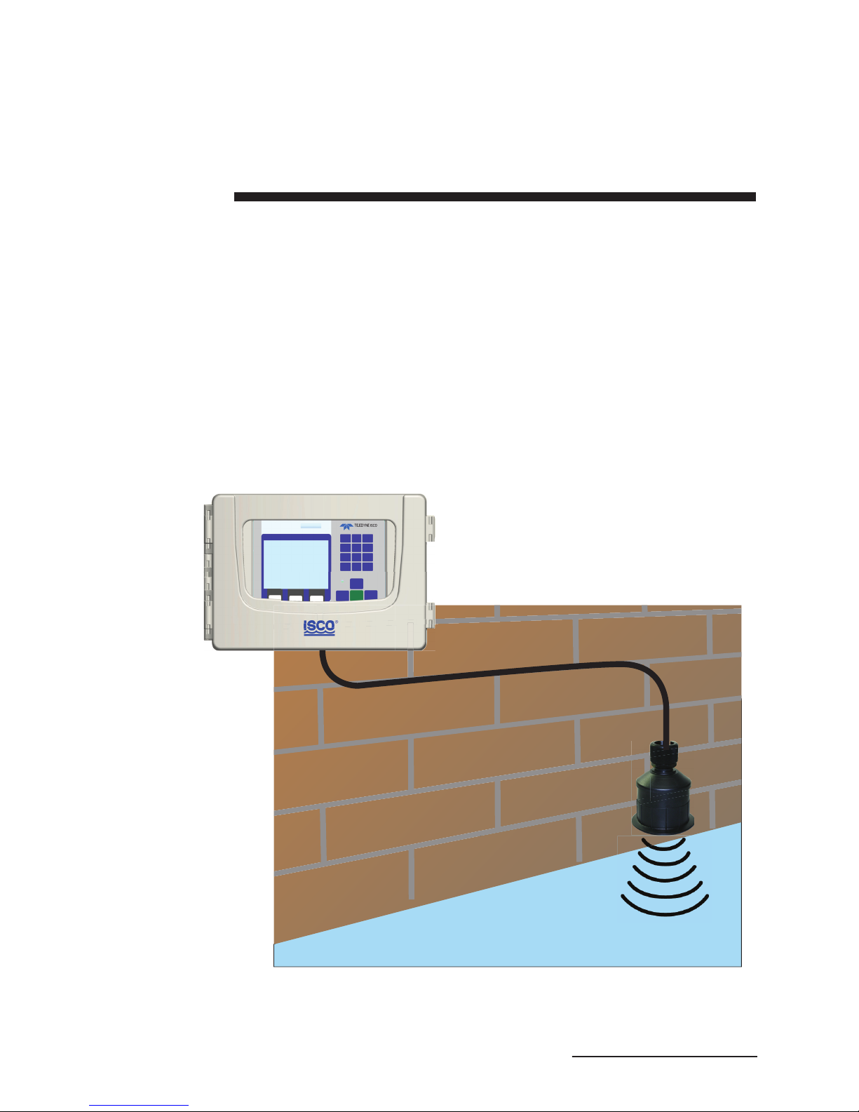
The Signature® Flow Meter uses the TIENet 310 Ex Device to
provide non-contact liquid level measurement. The flow meter
has built-in level-to-flow conversions that cover the majority of
open channel flow measurement situations.
1.1 Description The ultrasonic sensor is mounted over the flow stream. The flow
meter measures the time interval between transmission of a
sound pulse from the sensor, and receiving its echo off the surface
of the liquid, to determine the level of the stream.
Figure 1-1 Basic Signature monitoring system with
310 Ex (mounting hardware not shown)
Signature Flow Meter
310 Ex TIENet Sensor

TIENet® Model 310 Ex Ultrasonic Level Sensor
Section 1 Introduction
1-2
This non-contact measurement method reduces the frequency of
maintenance, and is ideal for applications where the flow may
contain chemicals, grease, silt, or suspended solids.
1.2 310 Ex Sensor Design The ultrasonic level sensor consists of a housing with a single
transducer that is both pulse transmitter and echo receiver. A
temperature sensor within the housing measures the ambient
temperature, and a microprocessor automatically compensates
for speed-of-sound changes due to any changes in air temper-
ature.
The 310 Ex is available with a 10m, 23m, and special order to
150m or less cable lengths with or without connectors. For
greater distances, external connection via conduit, and con-
nection of additional TIENet devices, the TIENet Expansion Box
is available. Bulk TIENet cable may also be used for greater dis-
tances.
Figure 1-2 310 Ex Ultrasonic TIENet Sensor with
unterminated leads (l) or TIENet plug (r)
1.3 Operation The sensor emits multiple ultrasonic pulses per second. Between
pulses, the transducer switches from transmitter to receiver.
When the transducer receives the echo from the water’s surface,
the sound energy is converted into an electrical signal. The
signal is then amplified and processed by the Signature flow
meter into an “echo-received” signal. The time between the trans-
mitted pulse and the echo-received signal is proportional to the
distance between the transducer and the liquid surface. This dis-
tance in turn determines the liquid level used to calculate flow.

TIENet® Model 310 Ex Ultrasonic Level Sensor
Section 1 Introduction
1-3
1.4 Technical
Specifications
Table 1-1 310 Ex TIENet Device Specificationsa
Sensor Dimensions 3.63" x 4" tall (9.1cm x 10.2cm tall)
Cable Length 10 or 23 meters standard (32.8 or 75.5ft) standard
Mounting Attachment 3/4" NPT Pipe thread nipple w/ Conduit lock nut
Weight 4 lbs (1.8 kg)
Body Material PVDF
Enclosure IP68 when connected and properly sealed with cord-grip fitting.
Temperature Range
Operating (compensated)
Storage
Hazardous Locations
-22 to 140°F (-30 to 60°C)
-40 to 158°F (-40 to 70°C)
-40 to 140°F (-40 to 60°C)
Measurement Range Minimum: 1 ft (0.3m) from sensor to liquid surface
Maximum: 11 ft (3.3m) from sensor to liquid at minimum level
Measurement Accuracy
at 72 °F (22 °C)
±0.02ft (0.006m) at 1ft level change or less;
±0.03ft (0.009m) at greater than 1ft level change
Temperature Coefficient within compensated
range
± 0.0002 x D (m) per degree C
± 0.00011 x D (ft) per degree F
(Where D is the distance from the transducer to the liquid surface)
Beam Angle 10° 5° From center line
Ultrasonic Signal 50KHz
Certifications Group II, Category 1G (zone 0), T4
Class I, Division 1 (and Zone 0), T4
a. All specifications are subject to change without notice.

TIENet® Model 310 Ex Ultrasonic Level Sensor
Section 1 Introduction
1-4
1.5 Accessories Accessories used in sensor installation are briefly described
below. Refer to the next section for ordering information.
Note
Only the Wall Mount Bracket is approved for use in classified
hazardous locations. Other accessories must undergo a haz-
ardous location evaluation in order to fulfill safe installation
requirements.
Spreader Bar – The Spreader Bar is an expandable pipe for
suspending equipment inside a manhole. Outward spring
pressure secures it against the manhole walls, like a shower
curtain rod. Depending on your application, you can then
suspend the 310 Ex TIENet Device, or the Signature Flow Meter
itself, from the bar.
Cable Straightener – The cable straightener is designed for
use in installations where the transducer is suspended by its
cable only, such as from the Spreader Bar. The straightener helps
hold the transducer vertically plumb, thereby stabilizing
alignment.
Cable Clamp – The cable clamp is used with the Spreader Bar
to secure the mounting of the sensor.
Wall Mount Bracket – This device lets you install the ultra-
sonic level sensor on a convenient nearby wall over a flow
stream, such as the side of a bridge, or other structure.
Floor Mount – The Ultrasonic Floor Mount is a collapsible
metal stand attached to the floor, for extending the sensor out
over a flow stream.
Ultrasonic Calibration Target – This option is designed to
make calibration of the level sensor more accurate during the
installation process by letting you calibrate the level sensor from
outside the manhole.
Sunshade – The ultrasonic sunshade is a white plastic cap that
fits over the top of the ultrasonic transducer. Its purpose is to
keep sunlight from heating the body of the level transducer and
introducing temperature errors to the internal temperature com-
pensation.
1.5.1 Ordering Information Options and accessories can be purchased by contacting Teledyne
Isco’s Customer Service Department.
Teledyne Isco
Customer Service Dept.
P.O. Box 82531
Lincoln, NE 68501 USA
Phone: 800 228-4373
402 464-0231
FAX: 402 465-3022
E-mail:[email protected]

TIENet® Model 310 Ex Ultrasonic Level Sensor
Section 1 Introduction
1-5
1.5.2 TIENet 310 Ex
Ultrasonic Level
Sensor
310 Ex Ultrasonic Level Sensor with Signature connection ending in unterminated leads.
For use with Signature 6 position plug-in (green) terminal strip.
Includes cord grip and sensor with cable. (See cable lengths below).
310 Ex Ultrasonic sensor w/ 10m cable................................................................................... 60-4314-005
310 Ex Ultrasonic sensor w/ 23m cable................................................................................... 60-4314-006
310 Ex Ultrasonic sensor Cut-to-length.................................................................................. 60-4314-014
Cut to length cable up to 999 ft* ............................................................................................. 60-4304-050
*Cable lengths can go up to 150 m with an expansion box.
310 Ex Ultrasonic Level Sensor with Signature connection ending in TIENet plug. For use
with portable Signature TIENet receptacle.
Includes cord grip and sensor with cable. (See cable lengths below).
310 Ex Ultrasonic sensor w/ connector and 10m cable .......................................................... 60-4314-009
310 Ex Ultrasonic sensor w/ connector and 23m cable .......................................................... 60-4314-011
310 Ex Ultrasonic sensor w/ connector Cut-to-length*. ......................................................... 60-4314-013
Cable Assembly with TIENet Y w/ connector ......................................................................... 60-4304-066
*Cable lengths can go up to 150 m with an expansion box.
Sunshade for ultrasonic sensor ............................................................................................... 60-3004-142
Spreader bar for suspension of sensor or flow meter in manhole shaft ................................ 60-3004-110
Cable clamp .............................................................................................................................. 60-3004-129
Sensor Mounting Bracket U/S ................................................................................................. 60-2003-615
Floor mount for horizontal surfaces ........................................................................................ 60-2004-611
Cable straightener for suspension over stream...................................................................... 60-4313-009
Ultrasonic calibration target ................................................................................................... 60-3004-143
TIENet Expansion Box............................................................................................................. 60-4307-023
Kit includes 10ft TIENet cable
Cord grip fitting, 3/4" NPT, for TIENet cable........................................................................... 209-0073-12
Barrier for Signature (SPA 2060) ............................................................................................ 60-5324-060
Note
Teledyne Isco uses FreeRTOS version 5.4.2 in its TIENet
devices. In accordance with the FreeRTOS license, FreeRTOS
source code is available on request. For more information, visit
www.FreeRTOS.org.

TIENet® Model 310 Ex Ultrasonic Level Sensor
Section 1 Introduction
1-6

2-1
TIENet® Model 310 Ex Ultrasonic
Level Sensor
Section 2 Installation and Setup for Signature
The Signature Flow Meter does not have to be mounted near the
flow stream. You can install the flow meter itself at a convenient,
protected location and route the sensor cable to the measurement
point. Proper installation of the 310 Ex sensor is critical for
accurate measurement.
2.1 Sensor Installation
Considerations
Measurement accuracy can be affected by a number of site
factors that should be taken into consideration when selecting
the location for the sensor. If the sensor cannot obtain a valid
reading, an asterisk (*) will appear next to the displayed level,
indicating there is an error.
2.1.1 Beam Angle The 310 Ex sensor has a 10° beam angle, forming a cone whose
apex is the ultrasonic transducer. The sensor can only detect sur-
faces within this cone. Narrow channels can result in false echoes
and incorrect level readings off the walls and sides of the
channel. For preventive measures, see Section 2.5.2 Mea-
surement Setup, and the programming steps in Figure 2-14.
The beam becomes narrower at shorter distances, which can
increase difficulty in detecting the return echo. If the beam is too
wide, the sensor may pick up signals from unwanted surfaces,
such as the walls of the channel.
Sensor elevation is highly specific to the particular site.
2.1.2 Humidity Conditions of extremely high or low humidity can cause detection
to occur either earlier or later than under normal conditions. A
drop in water level, normally compensated for by the sensor’s
interval-based amplifier, may produce errors in echo detection.
Additionally, water droplet condensation on the bottom surface of
the sensor can cause measurement errors.
2.1.3 Surface Solids, foam, oil, and turbulence can all absorb or weaken the
ultrasonic pulses, causing errors in detection. Foam or oil on the
surface of the stream can produce false level readings.
2.1.4 Temperature Changes in ambient temperature significantly affect the velocity
of sound. If ambient temperature changes rapidly, there may be a
delay before the 310 Ex’s temperature sensor can activate tem-
perature compensation.
If the sensor will be installed outdoors in direct sunlight, use a
sunshade to prevent heating of the sensor housing.

TIENet® Model 310 Ex Ultrasonic Level Sensor
Section 2 Installation and Setup for Signature
2-2
2.1.5 Waves Waves on the surface of the flow stream can deflect the ultrasonic
signal, causing erroneous readings or total loss of signal. The
Signature Flow Meter software is able to reject occasional
readings that deviate substantially from normal.
2.1.6 Wind Strong winds can significantly reduce the strength of the return
echo. Narrow beams can result in the sound being blown away;
likewise, greater distances to the flow stream surface are more
subject to distortion in strong winds.
2.1.7 Hazardous Locations Installation in classified hazardous locations must meet specific
conditions in order to fulfill safety requirements. Installation
must be performed only by trained, qualified personnel. Refer to
Section 2.4 Installation in Hazardous Locations for complete
information.
2.2 Connecting the Cable External TIENet devices such as the 310 Ex are all connected to
the Signature flow meter in the same manner. These connections
usually use conduit or cord-grip cable fittings for permanent
mounted meter or with TIENet receptacle for portable meters.
Multiple external TIENet devices can be connected simultane-
ously.
Refer to your Signature flow meter manual for instructions on
accessing the instrument’s interior components.
Note
The steps that follow include instructions for installing cord-grip
fittings. Some applications will require cables to be routed
through user-supplied conduit. Conduit with a minimum 3/4"ID
is suggested for unterminated sensor cables and conduit with
minimum 1-1/2” ID is suggested for straight runs for sensor
cables with connectors.
2.2.1 Permanent Meters
Note
Before proceeding, ensure that the flow meter has been dis-
connected from mains power.

TIENet® Model 310 Ex Ultrasonic Level Sensor
Section 2 Installation and Setup for Signature
2-3
1. Remove one of the 6-position plug-in terminal strip connec-
tors from the case board.
Figure 2-1 TIENet Device terminal strips
2. If using a cord-grip fitting, install the cable nut in the
appropriate opening on the bottom of the Signature enclo-
sure, securing it to the wall with the lock nut (concave side
facing wall).
3. Feed the TIENet device cable end through the sealing nut
and seal, and through the cable nut. Lightly tighten the
sealing nut, just enough to hold the cable in place while
installing the connector.
Figure 2-2 Installing cable with a cord-grip fitting
4. Attach the wire ends to the terminal strip as shown in
Figure 2-3, then press the terminal strip back down into its
socket on the case board, as shown in Figure 2-4, taking
care not to strain any wire connections. Gently tug each
wire when finished, to verify secure connection to the
screw terminals.
Lock Nut
(concave side
facing wall)
Cable Nut
Seal
(color may vary)
Sealing Nut

TIENet® Model 310 Ex Ultrasonic Level Sensor
Section 2 Installation and Setup for Signature
2-4
Note
The SHIELD wire is the bare drain emerging from the foil
shield around the YELLOW and BROWN wires. The
BRAID-DRAIN wire is the bare drain emerging from the sur-
rounding braided shield inside the cable jacket. It is not neces-
sary to prevent the two braids from coming into contact with
each other.The drain wires need to be kept very short.
Figure 2-3 TIENet Device terminal connections
5. Press the terminal strip back down into its socket on the
case board, as shown in Figure 2-5, taking care not to
strain any wire connections. The 310 Ex sensor cable does
not include a reference air connection (Figure 2-4).
Figure 2-4 Attach wired terminal strip to case board socket
Braid-Drain
Shield

TIENet® Model 310 Ex Ultrasonic Level Sensor
Section 2 Installation and Setup for Signature
2-5
6. Gently tug the cable downward, to remove any slack within
the enclosure, taking care not to put any stress on the con-
nection.
7. Tighten the cord grip sealing nut.
CAUTION
If you are using conduit instead of the cord-grip fitting, the con-
duit must be sealed to prevent harmful gases and moisture
from entering the Signature enclosure. Failure to seal conduit
could reduce equipment life.
8. Close the front panel and fasten it shut with the two Phil-
lips screws.
Figure 2-5 Position and secure the cable
2.2.2 Connecting to
Signature Portable via
a TIENet Receptacle
The optional external TIENet devices compatible with the Sig-
nature Portable (and Signature) all scan into the hardware in the
same manner. A scan is required anytime a new TIENet device is
added.
Multiple TIENet devices can be connected simultaneously to the
same Signature Portable Flow Meter. The following TIENet
devices will attach to the TIENet receptacle:
• Ultrasonic Level Sensor

TIENet® Model 310 Ex Ultrasonic Level Sensor
Section 2 Installation and Setup for Signature
2-6
• Area Velocity Sensor
• 301 pH Interface
• LaserFlow
• 306 Sampler Interface
Connecting a TIENet plug
to the Signature Portable
To connect the TIENet plug from the sensor to the TIENet Recep-
tacle:
1. Align the connectors and push together (Figure 2-6).
2. After the physical connection is made, a scan must be per-
formed for the device to be recognized.
For additional TIENet connections, use the TIENet Y-cable or
alternately an Expansion Box.
O-Ring and Lubrication
for the TIENet receptacle
1. Coat the O-ring’s sealing surface with a silicone lubricant.
CAUTION
Do not use petroleum-based lubricants. Petroleum-based
lubricants will cause the O-ring to swell and eventually deterio-
rate. Aerosol silicone lubricant sprays often use petro-
leum-based propellents. If you are using an aerosol spray,
allow a few minutes for the propellent to evaporate before pro-
ceeding.
2. Align and insert the connector. The sensor release will
“click” when the sensor connector is fully seated.
3. Connect the two caps together.
Figure 2-6 How to connect a TIENet plug to the Signature
Portable
2.3 Sensor Installation The mounting location of the ultrasonic level sensor depends on
the type of primary measuring device (such as a weir or flume),
and on the method of level-to-flow conversion used. Refer to the
Isco Open Channel Flow Measurement Handbook included with
your Signature flow meter, or to instructions provided by the
manufacturer of the primary device, for detailed information
about locating the measuring point.
Table of contents
Other Teledyne Accessories manuals

Teledyne
Teledyne Everywhereyoulook CCD261-04 User manual

Teledyne
Teledyne 452 User manual

Teledyne
Teledyne HVD3000 User manual

Teledyne
Teledyne TIENet 360 LaserFlow Ex Operating instructions

Teledyne
Teledyne Citadel CTD-ES User manual

Teledyne
Teledyne PP007 User manual

Teledyne
Teledyne BOA Spot ID Series User manual

Teledyne
Teledyne 2150 Operating instructions

Teledyne
Teledyne UFO-130 User manual

Teledyne
Teledyne TIENet 350 Operating instructions