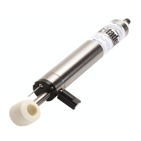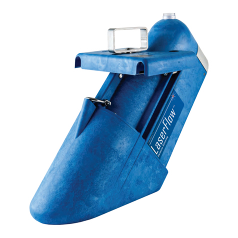
2150 Area Velocity Flow Module
Table of Contents
vi
Section 3 Programming
3.1 Section Overview ....................................................3-1
3.2 Flowlink Connections ................................................3-1
3.2.1 Communication Resolution ......................................3-2
3.3 Program Settings....................................................3-2
3.3.1 Level ........................................................3-3
3.3.2 Zero Level Offset ..............................................3-4
3.3.3 No Velocity Data and Flow Rates .................................3-5
3.3.4 Prevent Velocity Signal Interference ..............................3-5
3.3.5 Flow Conversion ...............................................3-6
3.3.6 Silt Level ....................................................3-7
3.3.7 Data Storage Rates ............................................3-7
3.3.8 Site Name ....................................................3-8
3.3.9 Module Name .................................................3-8
Section 4 Modbus Output Protocol
4.1 Introduction ........................................................4-1
4.2 Operation ..........................................................4-1
4.2.1 Establishing Communication ....................................4-2
4.2.2 Module Addressing ............................................4-2
4.3 Configurations ......................................................4-3
4.4 Glossary of Terms ...................................................4-4
4.5 Common Acronyms ..................................................4-5
4.6 Register Specifications ...............................................4-5
Section 5 Maintenance
5.1 Maintenance Overview ...............................................5-1
5.2 Maintenance Kits ...................................................5-1
5.3 Batteries...........................................................5-2
5.4 Desiccant ..........................................................5-2
5.4.1 Replacing the Desiccant: AV Module ..............................5-2
5.4.2 Replacing the Desiccant: Battery Module ..........................5-3
5.4.3 Reactivating the Desiccant ......................................5-3
5.5 Channel Conditions..................................................5-4
5.6 Other Maintenance ..................................................5-4
5.6.1 Hydrophobic Filter .............................................5-4
5.6.2 Cleaning .....................................................5-4
5.6.3 Sensor Cable Inspection ........................................5-5
5.7 How to Obtain Service ...............................................5-5
5.7.1 Diagnostics ...................................................5-5
Appendix A Replacement Parts
A.1 Replacement Parts Diagrams and Listings...............................A-1
Appendix B Accessories
B.1 How to Order.......................................................B-1
B.2 General Accessories .................................................B-1
B.3 Maintenance Kits ...................................................B-1
B.4 AV Sensor Mounting Accessories.......................................B-2
Appendix C Material Safety Data Sheets
C.1 Overview ..........................................................C-1


