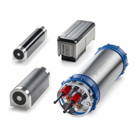
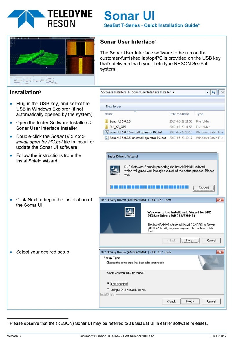
Teledyne SeaBat T-Series User manual

Use and Disclosure of Data
EU Uncontrolled Technology:
Information contained herein is uncontrolled under the EU-regulation no. 821 of 20 May 2021.
However, export, reexport or diversion contrary to law is prohibited.
SeaBat T-Series Rackmount
SeaBat T20-R and T50-R High-Resolution
Multibeam Sonar System
OPERATOR'S MANUAL
Part Number 1008754
Version 9
December 2021

SeaBat T-Series Rackmount Operator's Manual
Page ii
December 15, 2021
Version 9
Uncontrolled Technology Subject to Restrictions Contained on the Cover Page.
Copyright Teledyne RESON A/S 2016-2021
Copyright
Statement
All rights reserved. Reproduction, adaptation, or translation without prior written permission is
prohibited, as per the copyright laws of Denmark.
SeaBat T-Series Rackmount Operator's Manual written by:
Teledyne RESON A/S
Fabriksvangen 35
3550 Slangerup
Telephone: +45 47 38 00 22
Facsimile: +45 47 38 00 66
Web: http://www.teledynemarine.com/reson
E-mail: [email protected]
Notice
The information contained in this document is subject to change without notice. Teledyne RESON
makes no warranty of any kind with regard to this material, including (but not limited to) the implied
warranties of merchant liability and fitness for a particular purpose. Teledyne RESON shall not be
liable for errors contained herein or for incidental or consequential damages in connection with the
furnishing, performance, or use of this material.
Copyright
Release
No part of this manual may be copied or distributed, transmitted, transcribed, stored in a retrieval
system, or translated into any human or machine readable language, in any form or by any means
for disclosure to third parties without the express written consent of Teledyne RESON A/S.
Version
December 2021
Version 9
Teledyne RESON strives to maintain up-to-date information and may, as necessary, review and
revise this manual. If the information contained in this manual is unclear, please contact your
nearest Teledyne RESON office for clarification.
Software
Release
2.0 or higher
This manual is consistent with the indicated release versions.
Electronic
File Version
This manual is available from Teledyne RESON in the Adobe® Acrobat® Portable Document
Format (PDF). The selected PDF process preserves the interactive index and cross-reference
features of the original Microsoft Word document.

SeaBat T-Series Rackmount Operator's Manual
Page iii
December 15, 2021
Version 9
Uncontrolled Technology Subject to Restrictions Contained on the Cover Page.
PREFACE – ABOUT THIS MANUAL
This manual is designed to give detailed procedures for the correct installation, operation, and
maintenance of the SeaBat T-Series Rackmount sonar system and is equally useful for both the
first time user and the experienced technician.
Read this manual thoroughly and follow the steps provided to maintain optimal safety standards
and to obtain the best system performance.
If you require additional information or need clarification of any part of this document, please
Document Conventions
The following information will make it easier for the reader to interpret the document content.
Convention
Definition
Hyperlink
Indicates a cross-reference to Ctrl+Click to reach the specified item.
Numbered list
Indicates stepwise instructions to be followed in a particular order.
Bulleted list
Indicates items of a list without any particular order.
Notes, Cautions, and Warnings
Notes, Cautions, and Warnings are included to provide valuable information and to help the
operator prevent damage to the sonar or to personnel. These are the formats:
NOTE
Note boxes provide explanatory information that may be useful to the operator, but is not
necessarily vital to the operation of your Teledyne RESON system.
CAUTION
Caution boxes provide important information regarding your Teledyne RESON system.
Disregarding Cautions may result in accidental misuse or damage to the system.
WARNING!
Warning boxes provide important information regarding your Teledyne RESON system.
Disregarding Warnings may prove harmful to personnel working with or near the system.
Conversion of Units of Measurement
Metric Conversion
All measurements in this manual are
referenced in metric terms.
Use this reference table to convert between
metric (e.g. cm, m, and km) and imperial (e.g.
in, ft, and yd) measurements.
Metric Unit
Imperial Unit
Millimeter (mm)
0.0394in
Centimeter (cm)
0.3937in
Meter (m)
1.0936yd
Kilometer (km)
0.6214mi
Kilogram (kg)
2.2046lb

SeaBat T-Series Rackmount Operator's Manual
Page iv
December 15, 2021
Version 9
Uncontrolled Technology Subject to Restrictions Contained on the Cover Page.
Temperature Conversion
All temperatures in this manual are referenced
in degrees Celsius.
This is the formula for converting Celsius (C)
to Fahrenheit (F).
Formula: F =
1.8 x C + 32
Example:
If Temperature =
30C, then:
F =
1.8 x 30+ 32
F =
86
Glossary of Terms
Entry
Definition
7k
SeaBat 7000 series of multibeam sonars
BITE
Built-In Test Environment
CE
Conformité Européenne
CFE
customer-furnished equipment
CW
Continuous wave
Cylindrical loss
The loss of sound by spreading in the form of a cylinder
DFD
Data Format Definition
DWG
Drawing
EA
Equiangular
ED
Equidistant
ER
Extended Range (TC2187 projector)
FM
Frequency modulation
FRDH
Full Rate Dual Head
INS
Inertial Navigation System
LED
light-emitting diode
N/A
not available or not applicable
OM
Operator’s Manual
PN
Part Number
RH
relative humidity
RMA
Return Material Authorization
ROV
Remotely Operated Vehicle
RSP
Rack-mounted Sonar Processor
Rx
receiver
SNR
signal-to-noise ratio
Spherical loss
The loss of sound by spreading in the form of a sphere
SV
sound velocity (or surface vessel as in SB 7125 SV)
SVP
Sound Velocity Probe
TBD
To Be Defined
TPU
Total Propagated Uncertainty
TVG
Time-Varied Gain is a control intended to vary the gain of an amplifier over a
predetermined time period (usually from a low to a high gain state)
Tx
transmitter
UI
user interface
WEEE
Waste Electrical and Electronic Equipment
ZDA
Time and date identifier

SeaBat T-Series Rackmount Operator's Manual
Page v
December 15, 2021
Version 9
Uncontrolled Technology Subject to Restrictions Contained on the Cover Page.
TABLE OF CONTENTS
1 Introduction...................................................................................................1
1.1 System Overview..............................................................................................................1
1.2 System Architecture .........................................................................................................2
1.3 System Operation.............................................................................................................3
1.4 System Features ..............................................................................................................3
1.5 Typical Applications..........................................................................................................6
1.6 Available SeaBat T-Series Rackmount Configurations ....................................................7
2 Safety Precautions .......................................................................................8
2.1 Operator Safety ................................................................................................................8
2.2 Equipment Safety .............................................................................................................8
2.2.1 Safe Handling ...........................................................................................................8
2.2.2 Cleaning and Maintenance .......................................................................................9
2.3 Corrosion Avoidance ......................................................................................................11
2.4 Electrical Isolation ..........................................................................................................12
2.5 Exposure to Sunlight ......................................................................................................12
2.6 Safe Disposal of Waste (WEEE Directive) .....................................................................12
2.7 CE Marking.....................................................................................................................13
3 System Startup and Shutdown..................................................................14
3.1 Chapter Overview...........................................................................................................14
3.2 System Startup Instructions ...........................................................................................15
3.3 Starting the Sonar User Interface...................................................................................15
3.4 System Shutdown Instructions .......................................................................................17
3.5 System Wake Up............................................................................................................18
4 System Configuration and Operation .......................................................19
4.1 Chapter Overview...........................................................................................................19
4.2 Remote Operation ..........................................................................................................19
5 Active Sonar Usage ....................................................................................20
5.1 Chapter Overview...........................................................................................................20
5.2 Enhancing Sonar Performance ......................................................................................21
5.2.1 Correct Range Setting ............................................................................................21
5.2.2 Transmit Power.......................................................................................................22
5.2.3 Ping Rate ................................................................................................................23
5.2.4 Receiver Gain .........................................................................................................23
5.2.5 Frequency Selection ...............................................................................................24
5.2.6 Pulse Length...........................................................................................................24
5.2.7 Pulse Type..............................................................................................................25
5.2.8 Vari-Swath ..............................................................................................................25
5.2.9 Use of Beam Mode .................................................................................................28
5.2.10 Use of Gates...........................................................................................................30
5.2.11 Maximizing Quality of Backscatter for Snippets Data .............................................33
5.3 Enhancing System Efficiency .........................................................................................33
5.3.1 Multi-Detect Operation............................................................................................33
5.3.2 Tracker Autopilot.....................................................................................................34
5.3.3 Roll Stabilization .....................................................................................................34
5.3.4 Head Tilt .................................................................................................................35
5.4 Compensation for Environmental Conditions .................................................................37
5.4.1 Loss of Sound by Absorption..................................................................................37

SeaBat T-Series Rackmount Operator's Manual
Page vi
December 15, 2021
Version 9
Uncontrolled Technology Subject to Restrictions Contained on the Cover Page.
5.4.2 Loss of Sound by Spreading...................................................................................38
5.4.3 Sound Velocity........................................................................................................39
5.5 Limitations ......................................................................................................................40
5.5.1 Cavitation................................................................................................................40
5.5.2 Machinery Noise .....................................................................................................41
5.5.3 Interference from Other Sonar Systems .................................................................41
5.5.4 Speed .....................................................................................................................41
5.5.5 Air Bubbles .............................................................................................................42
5.5.6 Environment............................................................................................................42
6 System Performance and Data Types ......................................................43
6.1 System Components ......................................................................................................45
6.1.1 Rack-mounted Sonar Processor (RSP)..................................................................45
6.1.2 EM7218 Receiver Unit............................................................................................46
6.1.3 EM7219 Receiver Unit (alternative)........................................................................46
6.1.4 TC2181 Projector Unit ............................................................................................46
6.2 Selectable Beam Density ...............................................................................................47
6.2.1 Beam Modes...........................................................................................................47
6.2.2 Equi-Distant, Equi-Angle, and Intermediate Modes................................................48
6.3 Data Types .....................................................................................................................50
6.3.1 Bathymetry Data .....................................................................................................50
6.3.2 Side-Scan Data.......................................................................................................50
6.3.3 Snippets Backscatter ..............................................................................................50
6.4 Real-Time Pipe Detection and Tracking.........................................................................52
6.5 Multi-Detect ....................................................................................................................53
6.6 X-Range Performance....................................................................................................53
6.7 Full Rate Dual Head .......................................................................................................53
6.8 Quality ............................................................................................................................54
6.8.1 Brightness Test.......................................................................................................54
6.8.2 Colinearity Test.......................................................................................................55
6.8.3 Quality Filter............................................................................................................55
6.9 Uncertainty Estimation ...................................................................................................55
6.10 Hydrodynamic Drag........................................................................................................56
6.10.1 Drag Simulation Setup............................................................................................56
6.10.2 Drag Simulation Conclusions..................................................................................56
6.10.3 Drag Simulation Results .........................................................................................57
6.11 Ping Rate Table..............................................................................................................65
Appendix A Troubleshooting.....................................................................66
A.1 System Error and Warning Messages............................................................................66
A.2 Error Messages ..............................................................................................................66
A.2.1 General System Startup Errors...............................................................................66
A.2.2 Data Reading Errors ...............................................................................................67
A.2.3 System Resource Errors.........................................................................................67
A.2.4 Input Signal (Timing and Triggers) Errors...............................................................67
A.2.5 Normalization Errors ...............................................................................................68
A.3 Warning Messages.........................................................................................................68
A.3.1 Configuration Warnings ..........................................................................................68
A.3.2 Data Processing Warnings .....................................................................................68
A.3.3 Data Recording Warnings.......................................................................................69
A.3.4 BITE Data Warnings ...............................................................................................69
A.3.5 Input Signal Warnings.............................................................................................69

SeaBat T-Series Rackmount Operator's Manual
Page vii
December 15, 2021
Version 9
Uncontrolled Technology Subject to Restrictions Contained on the Cover Page.
A.3.6 System Stability Warnings ......................................................................................69
A.3.7 Data Subscription Warnings ...................................................................................70
A.3.8 Network Components Warnings .............................................................................70
A.3.9 External Trigger Warnings ......................................................................................70
A.4 Error Messages – Master List in Alphabetical Order......................................................71
A.5 Warning Messages – Master List in Alphabetical Order ................................................74
Appendix B Installation Instructions.........................................................78
B.1 Components List ............................................................................................................78
B.2 Installation Checklist.......................................................................................................80
B.3 System Interfacing..........................................................................................................81
B.3.1 Interfacing Diagram for Standard Configurations ...................................................81
B.3.2 Interfacing Diagram for Configurations with Integrated INS ...................................83
B.4 Dry-End Installation ........................................................................................................85
B.4.1 Rack-mounted Sonar Processor (RSP)..................................................................85
B.4.2 Sonar Processor Mounting .....................................................................................85
B.4.3 Sonar Processor Cable Connections......................................................................86
B.4.4 Rack-mounted Sonar Processor Power Button and BITE LED ..............................87
B.5 Auxiliary Sensors............................................................................................................88
B.5.1 Standard SeaBat T20/50-R Configurations ............................................................88
B.5.2 SeaBat T20/50-R Configurations with Integrated INS ............................................89
B.5.3 Sound Velocity Input...............................................................................................89
B.5.4 Time Input...............................................................................................................89
B.5.5 Time Output (for optional INS configurations) ........................................................90
B.5.6 Motion Input ............................................................................................................90
B.5.7 Motion Output (for optional INS configurations)......................................................90
B.5.8 Standard Serial Ports..............................................................................................90
B.6 SeaBat T-Series Rackmount Cables..............................................................................91
B.7 Wet-End Installation .......................................................................................................92
B.7.1 EM7218 Receiver Unit (PN 85002409) ..................................................................92
B.7.2 EM7219 Receiver Unit (PN 85002436) ..................................................................92
B.7.3 TC2181 Projector Unit (PN 85002319)...................................................................93
B.7.4 Wet-End Cable Connections ..................................................................................93
B.7.5 Sonar Head Assembly Orientation .........................................................................94
B.7.6 Sonar Reference Point ...........................................................................................94
B.7.7 Wet-End Mounting ..................................................................................................95
B.7.8 Hardware ................................................................................................................96
B.8 System Check ................................................................................................................97
Appendix C PPS In and Trigger In.............................................................98
C.1 Electrical Specifications for PPS In and Trigger In.........................................................98
C.2 Typical PPS In and Trigger Performance.......................................................................98
C.3 Hints and Advice ............................................................................................................99
Appendix D Data Rates.............................................................................100
Appendix E Network Configuration ........................................................101
E.1 System Network Configuration.....................................................................................101
E.2 Change IP Configuration ..............................................................................................101
Appendix F Configuration of Integrated INS (optional).........................103
F.1 POS MV – How to Perform a GAMS Calibration..........................................................103
F.1.1 MV-POSView – Standby Mode.............................................................................103
F.1.2 GAMS Parameter Setup .......................................................................................103

SeaBat T-Series Rackmount Operator's Manual
Page viii
December 15, 2021
Version 9
Uncontrolled Technology Subject to Restrictions Contained on the Cover Page.
F.1.3 Positioning Quality ................................................................................................104
F.1.4 GAMS Calibration – Procedure ............................................................................105
F.2 POS MV – How to Set Up for a Multibeam Survey ......................................................109
F.2.1 Conventions..........................................................................................................109
F.2.2 Coordinate Frames ...............................................................................................109
F.2.3 Offsets – Example ................................................................................................110
F.2.4 Alignments – Example ..........................................................................................111
F.2.5 MV-POSView Software.........................................................................................111
F.2.6 Installation Parameters – Lever Arms & Mounting Angles ...................................112
F.2.7 Installation Parameters – Sensor Mounting..........................................................113
F.2.8 Installation Parameters – Tags, Multipath & AutoStart ........................................114
F.2.9 Installation Parameters – Heave Filter..................................................................114
F.2.10 POS MV Output– Serial Data ...............................................................................115
F.2.11 POS MV Output– Ethernet Realtime ....................................................................117
F.2.12 Acquisition Software .............................................................................................117
F.2.13 Patch Test Results................................................................................................117
F.2.14 POS Statistics.......................................................................................................118
Appendix G Interfacing Sensors To Teledyne PDS ...............................119
G.1 Establishing a Connection to the RSP .........................................................................119
G.2 Interfacing to Teledyne PDS ........................................................................................121
G.2.1 Configuring the Sonar UI to Output Data..............................................................121
G.2.2 Configuring Teledyne PDS ...................................................................................122
Appendix H Reference Documentation...................................................125
H.1 SeaBat T-Series Rackmount Documentation...............................................................125
H.2 SeaBat T-Series Rackmount Design Documents ........................................................126
H.2.1 Receiver, EM7219 Outline....................................................................................128
H.2.2 Receiver, EM7218 Outline....................................................................................129
H.2.3 Projector, TC2181 Outline ....................................................................................130
H.2.4 T20: Receiver EM7219 and Projector TC2181, Bracket Installation ....................131
H.2.5 T20 Bracket Installation: Sonar Reference Point..................................................132
H.2.6 T20 Bracket Installation with IMU Reference Point ..............................................133
H.2.7 T20 Bracket Installation with Fairing (optional).....................................................134
H.2.8 T50: Receiver EM7218 and Projector TC2181, Bracket Installation ....................135
H.2.9 T50 Bracket Installation: Sonar Reference Point..................................................136
H.2.10 T50 Bracket Installation with IMU Reference Point ..............................................137
H.2.11 T50 Bracket Installation with Fairing (optional).....................................................138
H.2.12 T20 Dual Head Bracket Installation (optional) ......................................................139
H.2.13 T20 Dual Head Bracket Installation (optional): Sonar Reference Point................140
H.2.14 T20 Dual Head Bracket Installation with Fairing (optional)...................................141
H.2.15 T20 Dual Head Bracket Installation with IMU Reference Points (optional)...........142
H.2.16 Narrow Head Adaptor (optional) for T20 Dual Head. Outline Assembly Drawing 143
H.2.17 Narrow Head Adaptor (optional) for T20 Dual Head. Outline ...............................144
H.2.18 Narrow Head Adaptor (optional) for T20 Dual Head. Outline with Fairing............145
H.2.19 Narrow Head Adaptor (optional) for T20 Dual Head. Sonar Reference Point ......146
H.2.20 Narrow Head Adaptor (optional) for T20 Dual Head with IMU. Sonar Reference
Point 147
H.2.21 T50 Dual Head Bracket Installation (optional) ......................................................148
H.2.22 T50 Dual Head Bracket Installation (optional): Sonar Reference Point................149
H.2.23 T50 Dual Head Bracket Installation with Fairing (optional)...................................150
H.2.24 T50 Dual Head Bracket Installation with IMU Reference Points (optional)...........151

SeaBat T-Series Rackmount Operator's Manual
Page ix
December 15, 2021
Version 9
Uncontrolled Technology Subject to Restrictions Contained on the Cover Page.
H.2.25 T50: Receiver EM7218 and Projector TC2187 (optional), Bracket Installation with
SVP 70 152
H.2.26 T50: Receiver EM7218 and Projector TC2187 (optional), Bracket Installation with
SVP 70 and Fairing .............................................................................................................153
H.2.27 T50: Receiver EM7218 and Projector TC2187 (optional), Bracket Installation,
Sonar Reference Point........................................................................................................154
H.2.28 T50: Receiver EM7218 and Projector TC2187 (optional), Bracket Installation, IMU
Reference Point ..................................................................................................................155
H.2.29 Cable Assembly, Rack-mounted Sonar Processor to Receiver ...........................156
H.2.30 Cable Assembly, Rack-mounted Sonar Processor to Projector ...........................157
H.2.31 Cable Assembly, Rack-mounted Sonar Processor to Projector ...........................158
H.2.32 Rack-mounted Sonar Processor with INS (optional) ............................................159
H.2.33 IMU Outline (optional)...........................................................................................160
H.2.34 IMU Motion Reference Points on T-Series Brackets (optional) ............................161
H.2.35 IMU Cable.............................................................................................................162
H.2.36 Antenna Outline ....................................................................................................163
H.2.37 Antenna Cable ......................................................................................................164
H.2.38 Cable Assembly, Sonar Processor to SVP 70 (optional)......................................165
H.2.39 Cable Assembly, Sonar Processor to SVP 71 (optional)......................................166
H.3 7kCenter Licenses – Copyright Information .................................................................167
Appendix I SeaBat T-Series Rackmount System Options...................172
I.1 Dual-Head Brackets .....................................................................................................172
I.2 Extended Range Projector ...........................................................................................172
I.2.1 System Performance ............................................................................................172
I.2.2 Mounting Bracket..................................................................................................173
I.3 Extended Warranty Contract ........................................................................................173
I.4 Fairings.........................................................................................................................173
I.5 Integrated Inertial Navigation System ..........................................................................173
I.6 SeaBat Cables .............................................................................................................173
I.7 Service Level Agreement .............................................................................................173
I.8 Sound Velocity Probe...................................................................................................174
I.9 System Integration and Training ..................................................................................174
I.10 Teledyne PDS Data Acquisition Software ....................................................................174
Appendix J Standard Warranty Information ..........................................175
J.1 One-Year Limited Warranty..........................................................................................175
J.2 Warranty Exclusions.....................................................................................................175
J.3 Warranty Disclaimer .....................................................................................................175
J.4 Servicing During Warranty Period ................................................................................175
J.5 Equipment Return Procedure.......................................................................................176
J.6 Teledyne RESON Support ...........................................................................................176
LIST OF FIGURES
Figure 1: SeaBat T-Series Rackmount System Configuration.........................................................2
Figure 2: SeaBat T-Series Rackmount System Configuration with Integrated INS (optional) .........2
Figure 3: Processor Filter Location................................................................................................11
Figure 4: Range Setting Diagrams ................................................................................................21
Figure 5: Range Setting – Too Long..............................................................................................21
Figure 6: Range Setting – Too Short .............................................................................................22

SeaBat T-Series Rackmount Operator's Manual
Page x
December 15, 2021
Version 9
Uncontrolled Technology Subject to Restrictions Contained on the Cover Page.
Figure 7: Range Setting – The Exception......................................................................................22
Figure 8: Example of Reduced Swath Width .................................................................................26
Figure 9: Horizontal Swath Steering ..............................................................................................27
Figure 10: Outer Beams for the Different Beam Modes with a Tilted Sonar Head ........................28
Figure 11: Graphic Illustration of FlexMode...................................................................................30
Figure 12: Depth Gates, With No Roll ...........................................................................................31
Figure 13: Depth Gates, With Roll .................................................................................................31
Figure 14: Depth Gates, With Roll and Motion Sensor Input.........................................................32
Figure 15: Depth Gate Tilt .............................................................................................................32
Figure 16: Submerged Oil Detected by Multi-Detect .....................................................................33
Figure 17: Swath under Zero Roll Conditions................................................................................34
Figure 18: Laterally Displaced Swaths under Roll Conditions .......................................................35
Figure 19: Swath under Roll Stabilization......................................................................................35
Figure 20: Head Tilt Functionality ..................................................................................................36
Figure 21: Head Tilt for Harbor Inspection.....................................................................................36
Figure 22: Head Tilt for Pipe Inspection ........................................................................................36
Figure 23: Acoustic Absorption Reference ....................................................................................38
Figure 24: Typical Sound Velocity Values .....................................................................................39
Figure 25: Rack-mounted Sonar Processor ..................................................................................45
Figure 26: EM7218 Receiver Unit..................................................................................................46
Figure 27: EM7219 Receiver Unit..................................................................................................46
Figure 28: TC2181 Projector Unit ..................................................................................................46
Figure 29: Beam Density ...............................................................................................................48
Figure 30: Beam Spacing vs. Beam Angle ....................................................................................48
Figure 31: Beam Spacing ..............................................................................................................49
Figure 32: Across-Track Sounding Location on a Flat Bottom ......................................................49
Figure 33: Graphic Illustration of Snippets Data ............................................................................51
Figure 34: SeaBat Real-Time Pipe Detection and Tracking ..........................................................52
Figure 35: SeaBat FlexMode .........................................................................................................52
Figure 36: Standard Detection.......................................................................................................53
Figure 37: Multi-Detect with enhanced detail on Quay Wall ..........................................................53
Figure 38: Multi-Detect ..................................................................................................................53
Figure 39: Dual Head Synchronization of Pings ............................................................................54
Figure 40: Brightness Test.............................................................................................................54
Figure 41: Colinearity Flags...........................................................................................................55
Figure 42: T20 Sonar Head Assembly in Bracket with Optional Front Fairing ..............................57
Figure 43: Flow at 10 knots around Single T20 with Fairing..........................................................57
Figure 44: Flow around Single T20 with Fairing, Cross Section of Symmetry Plane ....................57
Figure 45: Flow at 10 knots around Single T20 without Fairing.....................................................58
Figure 46: Flow around Single T20 without Fairing, Cross Section of Symmetry Plane ...............58
Figure 47: T20 Dual Sonar Head Assembly in Bracket with Optional Front Fairing ......................59
Figure 48: Flow at 10 knots around Dual T20 with Fairings ..........................................................59
Figure 49: Flow around Dual T20 with Fairings, Cross Section of Symmetry Plane .....................59
Figure 50: Flow at 10 knots around Dual T20 without Fairings .....................................................60
Figure 51: Flow around Dual T20 without Fairings, Cross Section of Symmetry Plane ................60
Figure 52: T50 Sonar Head Assembly in Bracket with Optional Front Fairing ..............................61
Figure 53: Flow at 10 knots around Single T50 with Fairing..........................................................61
Figure 54: Flow around Single T50 with Fairing, Cross Section of Symmetry Plane ....................61
Figure 55: Flow at 10 knots around Single T50 without Fairing.....................................................62
Figure 56: Flow around Single T50 without Fairing, Cross Section of Symmetry Plane ...............62

SeaBat T-Series Rackmount Operator's Manual
Page xi
December 15, 2021
Version 9
Uncontrolled Technology Subject to Restrictions Contained on the Cover Page.
Figure 57: T50 Dual Sonar Head Assembly in Bracket with Optional Front Fairing ......................63
Figure 58: Flow at 10 knots around Dual T50 with Fairings ..........................................................63
Figure 59: Flow around Dual T50 with Fairings, Cross Section of Symmetry Plane .....................63
Figure 60: Flow at 10 knots around Dual T50 without Fairings .....................................................64
Figure 61: Flow around Dual T50 without Fairings, Cross Section of Symmetry Plane ................64
Figure 62: T20/50-R, single/dual-head interfacing diagram...........................................................82
Figure 63: T20/50-R with integrated INS, single/dual-head interfacing diagram ...........................84
Figure 64: RSP Standard Configuration – Cable Connections......................................................86
Figure 65: RSP INS Configuration (optional) – Cable Connections ..............................................86
Figure 66: SVP, Motion, and Time Standard Connections ............................................................88
Figure 67: SVP, Motion, and Time Connections with Integrated INS (optional) ............................89
Figure 68: SeaBat T-Series Rackmount System Cables...............................................................91
Figure 69: Required PPS Pulse Width...........................................................................................98
Figure 70: PPS In Delay ................................................................................................................99
Figure 71: PPS/Trigger Signal .......................................................................................................99
Figure 72: Tate/Bryant Co-ordinate/Rotation System..................................................................109
Figure 73: Vessel Outline – Example ..........................................................................................110
Figure 74: IMU misalignment – Example.....................................................................................113
Figure 75: System Documentation Link (Example Only) .............................................................125
Figure 76: Receiver, EM7219 Outline..........................................................................................128
Figure 77: Receiver, EM7218 Outline..........................................................................................129
Figure 78: Projector, TC2181 Outline ..........................................................................................130
Figure 79: T20: Receiver EM7219 and Projector TC2181, Bracket Installation ..........................131
Figure 80: T20 Bracket Installation: Sonar Reference Point........................................................132
Figure 81: T20 Bracket Installation with IMU Reference Point ....................................................133
Figure 82: T20 Bracket Installation with Fairing (optional)...........................................................134
Figure 83: T50: Receiver EM7218 and Projector TC2181, Bracket Installation ..........................135
Figure 84: T50 Bracket Installation: Sonar Reference Point........................................................136
Figure 85: T50 Bracket Installation with IMU Reference Point ....................................................137
Figure 86: T50 Bracket Installation with Fairing (optional)...........................................................138
Figure 87: T20 Dual Head Bracket Installation (optional) ............................................................139
Figure 88: T20 Dual Head Bracket Installation (optional): Sonar Reference Point......................140
Figure 89: T20 Dual Head Bracket Installation with Fairing (optional).........................................141
Figure 90: T20 Dual Head Bracket Installation with IMU Reference Points (optional) ................142
Figure 91: Narrow Head Adaptor (optional) for T20 Dual Head. Outline Assembly Drawing ........143
Figure 92: Narrow Head Adaptor (optional) for T20 Dual Head. Outline .......................................144
Figure 93: Narrow Head Adaptor (optional) for T20 Dual Head. Outline with Fairing....................145
Figure 94: Narrow Head Adaptor (optional) for T20 Dual Head. Sonar Reference Point ..............146
Figure 95: Narrow Head Adaptor (optional) for T20 Dual Head with IMU. Sonar Reference Point147
Figure 96: T50 Dual Head Bracket Installation (optional) ............................................................148
Figure 97: T50 Dual Head Bracket Installation (optional): Sonar Reference Point......................149
Figure 98: T50 Dual Head Bracket Installation with Fairing (optional).........................................150
Figure 99: T50 Dual Head Bracket Installation with IMU Reference Points (optional) ................151
Figure 100: T50: Receiver EM7218 and Projector TC2187 (optional), Bracket Installation with
SVP 70.........................................................................................................................................152
Figure 101: T50: Receiver EM7218 and Projector TC2187 (optional), Bracket Installation with
SVP 70 and Fairing......................................................................................................................153
Figure 102: T50: Receiver EM7218 and Projector TC2187 (optional), Bracket Installation, Sonar
Reference Point ...........................................................................................................................154

SeaBat T-Series Rackmount Operator's Manual
Page xii
December 15, 2021
Version 9
Uncontrolled Technology Subject to Restrictions Contained on the Cover Page.
Figure 103: T50: Receiver EM7218 and Projector TC2187 (optional), Bracket Installation, IMU
Reference Point ...........................................................................................................................155
Figure 104: Cable Assembly, Rack-mounted Sonar Processor to Receiver ...............................156
Figure 105: Cable Assembly, Rack-mounted Sonar Processor to Projector ...............................157
Figure 106: Rack-mounted Sonar Processor ..............................................................................158
Figure 107: Rack-mounted Sonar Processor with INS (optional) ................................................159
Figure 108: IMU Outline (optional)...............................................................................................160
Figure 109: IMU Motion Reference Points on T-Series Brackets (optional) ................................161
Figure 110: IMU Cable.................................................................................................................162
Figure 111: Antenna Outline........................................................................................................163
Figure 112: Antenna Cable..........................................................................................................164
Figure 113: Cable Assembly, Sonar Processor to SVP 70 (optional)..........................................165
Figure 114: Cable Assembly, Sonar Processor to SVP 71 (optional)..........................................166
Figure 115: TC2187 Projector .....................................................................................................172
LIST OF TABLES
Table 1: SeaBat T-Series Rackmount Feature Pack.......................................................................3
Table 2: SeaBat T-Series Rackmount Available Configurations .....................................................7
Table 3: Incorrect Range Settings – Examples and Solutions.......................................................21
Table 4: TVG Formula ...................................................................................................................24
Table 5: SeaBat T-Series Rackmount System Performance.........................................................44
Table 6: Beam Modes with No. of Beams and Swath Coverage...................................................47
Table 7: Ping Rate Table ...............................................................................................................65
Table 8: SeaBat T-Series Rackmount Components......................................................................78
Table 9: RSP Technical Specifications..........................................................................................85
Table 10: RSP Port “SVP Com 3”..................................................................................................89
Table 11: RSP Port “Time In Com 1”.............................................................................................89
Table 12: RSP Port “Time Out Com 1” for optional INS ...................................................................90
Table 13: RSP Port “Motion In Com 2” ..........................................................................................90
Table 14: RSP Port “Motion Out Com 2” for optional INS.................................................................90
Table 15: RSP Ports “Com 4”, “Com 3-5” for optional INS ............................................................90
Table 16: EM7218 Receiver Unit Technical Specifications ...........................................................92
Table 17: EM7219 Receiver Unit Technical Specifications ...........................................................92
Table 18: TC2181 Projector Unit Technical Specifications............................................................93
Table 19: PPS In and Trigger In Signals .......................................................................................98
Table 20: Theoretical Max. Data Rates – SeaBat T-Series Rackmount Single and Dual Head..100
Table 21: IP Configuration for RSP .............................................................................................101
Table 22: Sensor Offsets .............................................................................................................110
Table 23: Sensor Alignments.......................................................................................................111
Table 24: POS MV Output Serial Data – COM Ports 1-2 ............................................................115
Table 25: SeaBat T-Series Rackmount Design Documents........................................................126
Table 26: LAPACK – Copyright Information ................................................................................167
Table 27: WinPCap – Copyright Information ...............................................................................168
Table 28: TC2187 Projector.........................................................................................................172
Table 29: SeaBat T50 Extended Range – System Performance ................................................172
Table 30: SVP Technical Specifications ......................................................................................174

INTRODUCTION
SeaBat T-Series Rackmount Operator's Manual
Page 1
December 15, 2021
Version 9
Uncontrolled Technology Subject to Restrictions Contained on the Cover Page.
1 INTRODUCTION
1.1 System Overview
The SeaBat T-Series Rackmount sonar system is the newest addition to the leading SeaBat
T-series product range, engineered from the ground up to evolve with your business. SeaBat T-
Series Rackmount is designed for very fast mobilization on any type of survey vessels, securing
minimal interfacing and low space requirements. The series is available in various configurations.
The SeaBat T20-R: Combined with a
Rack-mounted Sonar Processor (RSP),
SeaBat T20-R provides uncompromised
survey data in a highly compact package
designed for small vessel use.
The solution includes a range of powerful
software features at an attractive price,
with the option for future feature
expansions to grow with your needs.
The SeaBat T50-R: Combined with a very
compact Rack-mounted Sonar Processor
(RSP), the SeaBat T50-R produces
unprecedented clean data, providing faster
operational surveys and reduced
processing time.
The SeaBat T50-R is fully frequency agile
from 190 to 420kHz, allowing for improved
swath performance and reduced survey
time under challenging acoustic conditions.
Integrated Inertial Navigation System:
For both SeaBat T20-R and SeaBat T50-R,
the rack-mounted sonar processor is
available in an extended version for dual-
head sonar head configurations and an
optional industry-leading fully integrated
Inertial Navigation System for accurate
sensor time tagging and motion
stabilization.
For available configurations, see section 1.6 below.
For available options, see Appendix I SeaBat T-Series Rackmount System Options.

INTRODUCTION
SeaBat T-Series Rackmount Operator's Manual
Page 2
December 15, 2021
Version 9
Uncontrolled Technology Subject to Restrictions Contained on the Cover Page.
1.2 System Architecture
The SeaBat T-Series Rackmount multibeam sonar systems consist of a rack-mounted sonar
processor, a receiver unit (either EM7218 or EM7219), and a projector unit. User displays and
system control originate within the sonar processor.
For technical specifications, see Appendix B Installation Instructions.
Figure 1: SeaBat T-Series Rackmount System Configuration
The SeaBat T-Series Rackmount multibeam sonar systems are also available with an optional
state-of-the-art built-in and fully integrated Inertial Navigation System (INS).
Figure 2: SeaBat T-Series Rackmount System Configuration with Integrated INS (optional)
For additional options, see Appendix I SeaBat T-Series Rackmount System Options.
EM 7218 or EM 7219
Receiver(s)
TC 2181
Projector(s)
Sonar UI
hosted by
CFE laptop/PC
WET END
Rack-mounted Sonar
Processor
(RSP)
Time
Position
Motion
Sound velocity
DRY END
PPS
Sonar UI
hosted by
CFE laptop/PC
WET END
Rack-mounted Sonar
Processor
(RSP)
PPS
Time
Motion
Sound velocity
GPS
Antenna
GPS
Antenna
IMU
DRY END
EM 7218 or EM 7219
Receiver(s)
TC 2181
Projector(s)

INTRODUCTION
SeaBat T-Series Rackmount Operator's Manual
Page 3
December 15, 2021
Version 9
Uncontrolled Technology Subject to Restrictions Contained on the Cover Page.
1.3 System Operation
The projector unit of the sonar head assembly transmits a pulse of acoustic energy, which travels
through the water and is reflected by the seafloor or any objects in its path. The reflected signal is
received by the receiver unit of the sonar head assembly, digitized by internal electronics, and sent to
the topside rack-mounted sonar processor for beamforming and processing. The sonar processor
formats a digital output to be used by a peripheral data processing system while functioning as the
interface between the operator PC and the sonar system. Available data packages are documented in
the Data Format Definition Document (see Appendix H Reference Documentation).
The CFE laptop/PC running the RESON Sonar User Interface receives beam data, water column
data, bottom detection data etc. from the RSP and generates the wedge, water column, snippets, and
side-scan displays as well as other displays for sensor monitoring and general system Built-In Test
Environment overview.
1.4 System Features
Table 1: SeaBat T-Series Rackmount Feature Pack
Feature
Base
Optional
Channel normalization
Constant seafloor spacing
Dual head, full rate (FRDH)
Dual head, standard
FlexMode
Head tilt
Manual gates
Max. 1024 beams
Multi-detect
Normalized backscatter
On the fly frequency selection
On the fly beam mode selection
Pipe detection and tracking1
Quality filter
RESON Sonar User Interface
Roll stabilization
Selectable beam density
Tracker
Uncertainty output
Variable frequency
Vari-swath
Water column visualization
1Includes FlexMode.

INTRODUCTION
SeaBat T-Series Rackmount Operator's Manual
Page 4
December 15, 2021
Version 9
Uncontrolled Technology Subject to Restrictions Contained on the Cover Page.
Feature
Base
Optional
X-Range (FM)
Integrated INS (incl. external antennas and IMU)
Integrated Teledyne PDS2
NOTE
The Base feature set can be upgraded after installation.
The main features of the SeaBat T-Series Rackmount sonar systems are summarized below.
1PPS pulse handling and time stamping: Data time stamping is referenced to an
incoming 1PPS and associated time message.
Adaptive gating: Three different gate settings are available for application to the
bottom detection process: No Gates, Absolute Gates, and Adaptive Gates.
Beam data recording: The SeaBat T-Series Rackmount sonar systems are capable
of producing a stream of operator configurable beam data that may be written to a
shared network drive on either the CFE laptop/PC’s local hard drive or an optional
NAS (Network Attached Storage) RAID hard disk array. Data logging software
controls recording, playback, and data storage functions.
Beam distribution: The three standard beam spacing choices are equiangular,
intermediate, and equidistant spacing. In addition, the optional FlexMode provides
settings for alternative beam distribution. All options are dynamically focused.
Beamforming: The sonar processor performs initial signal processing, a combination
of time delay and phase rotation beamforming.
Bottom detection: The special bottom detection algorithm uses a combination of
center-of-energy and phase-zero crossing algorithms to detect the bottom in each
individual beam with the highest possible accuracy.
Built-In Test Environment (BITE): BITE is an integral part of the SeaBat T-Series
Rackmount sonar systems, monitoring the status of internal subsystems and the wet-
end units.
Compressed water column data: With this user configurable feature, it is possible to
make continuous recordings of water column backscatter data at significantly reduced
data volumes.
Constant seafloor spacing: This feature yields equidistant spacing between beams,
even on a sloping seafloor.
Data output: The SeaBat T-Series Rackmount sonar systems export the standard
hydrographic records of bathymetry, side-scan, and snippets as well as water column
data and other data for more scientific applications.
Depth rating: The SeaBat T-Series Rackmount sonar system wet end and cables are
depth-rated to 50 meters.
External trigger: The system may be triggered using a standard 7k Center software
remote command or by a TTL incoming trigger pulse.
2For details on this option, please contact Teledyne PDS at [email protected]

INTRODUCTION
SeaBat T-Series Rackmount Operator's Manual
Page 5
December 15, 2021
Version 9
Uncontrolled Technology Subject to Restrictions Contained on the Cover Page.
Fast update: The entire 140° (or 170°) swath is illuminated with a single transmission
at an update rate of up to 50Hz (range selection dependent), maintaining 100%
bottom coverage, even at high speed.
Full rate dual head: FRDH uses X-range (FM) to achieve dual-head operation with
the double effect of increased swath coverage and ping rate. With FRDH the systems
are synchronized and ping simultaneously at a high rate.
Hardware sync pulse out: A TTL pulse (synchronous with the transmit pulse) is
available from the sonar processor.
Head tilt: This feature makes it possible to operate with a physically rotated sonar
head, which allows for very flexible and specialized applications of the SeaBat T-
Series Rackmount sonar systems.
Integrated INS: An optional Inertial Navigation System (motion + position) uses GPS
for position and time, and IMU for measuring roll, heave, and acceleration.
Multi-detect: Providing up to five detections within each beam, including the full water
column, this feature allows the surveyor to capture enhanced details from a single
survey line over a complex feature, even in noisy environments.
Normalized backscatter: The normalized backscatter process is applied to the
snippet record to generate a magnitude signal that is compensated for the
characteristics of the sonar providing the operator with information that depends only
on the environment (seafloor).
On the fly beam mode selection: Choice of beam mode (spacing and number of
beams) can be done without interrupting the survey.
On the fly frequency change: The SeaBat T-Series Rackmount multi-frequency
systems may be operated at the full range of frequencies without interrupting the survey.
Operator selectable operating mode: With five different options, the operator is able
to select a beam mode appropriate to the application thereby optimizing sonar
operation. Equi-Angle and Intermediate modes yield a swath of 170º, while the other
three modes yield a swath of 140º or 150º in Equi-Distant mode for T50-R.
Real-time pipe detection and tracking: This SeaBat feature automatically detects
pipes within the multibeam swath, displays them to the user in real time during survey,
and sends the pipe positions to the data acquisition software. The feature builds on
FlexMode for generating a high-density profile of the pipe. The majority of the beams
are steered to the center of the detected pipe to track the pipe regardless of its
location on the wedge display.
Real-time QC display: The SeaBat T-Series Rackmount sonar systems generate a real-
time display with an intensity image on the CFE monitor. Overlaid on this intensity image
is the bottom detection display, giving the operator an excellent QC (quality control) tool.
Resolution: Dynamic, focused beamforming maintains ultra-high resolution, even at
short ranges. A receiver sample rate of 34/66kHz (34kHz for dual-head
configurations) provides unprecedented range resolution and complements the
narrow beam, thus providing the user with ultimate data quality and resolution.
Selectable beam density: This feature allows the surveyor to generate optimized
data volumes tailored to specific survey specifications by providing a choice of how
many beams to form ranging from the maximum capability of the system down to just
10. The configuration can be changed on the fly.
Steerable swath: This feature allows swath to be steered electronically.
Time stamping of sensor data: Time stamping of sensor data interfaced to the
Rack-mounted Sonar Processor (position, motion, and heading) is referenced to an

INTRODUCTION
SeaBat T-Series Rackmount Operator's Manual
Page 6
December 15, 2021
Version 9
Uncontrolled Technology Subject to Restrictions Contained on the Cover Page.
incoming 1PPS and associated time message (either serial or network), ensuring that
each data is time stamped to UTC to better than 1 millisecond, prior to broadcast over
standard Ethernet to the survey laptop/PC.
With the optional built-in, fully integrated INS, all time tagging will be handled by the INS.
Tracker: This feature is a complete automated mode of operation where the system
sets sonar control parameters, including range, gain, power, and swath width based
on the quality of the data being collected.
Uncertainty output: Uncertainty is computed for each sounding and presented
graphically on various UI (user interface) displays.
Variable swath coverage: This feature gives the operator control of the swath
coverage. It includes swath width settings ranging from 45º to 140º (150º for T50-R) in
Equi-Distant mode or 170º in Equi-Angle mode in increments of 5º as well as a choice
of beam density mode.
Water column visualization: Water column backscatter may be viewed in both the
across-track view (the sonar wedge) and in an along-track view, which allows the
surveyor to see a history of water column backscatter. Combined with the rolling water
column recording buffer, water column features of interest may be viewed and
recorded after they have been surveyed.
X-Range: X-Range is a software and hardware feature using frequency modulated
(FM) transmit pulses which provides extended range performance (across all
frequencies) and significantly improves system immunity to external noise.
1.5 Typical Applications
The SeaBat T-Series Rackmount is based around the sonar processor. The powerful scalable
feature set provides unmatched utility across a wide range of applications including:
As-built surveys
Breakwater mapping
Coastal mapping
Environmental research
Habitat mapping
Harbor mapping
Hydrographic surveys to IHO Special
Order and to U.S. Army Corps of
Engineers Special Order
Oil detection
Pipeline inspection surveys
Pipeline route surveys
Pre- and post-dredging and condition
surveys
Revetment surveys
River surveys
Search and recovery
Site clearance surveys
Underwater inspection and object
location

INTRODUCTION
SeaBat T-Series Rackmount Operator's Manual
Page 7
December 15, 2021
Version 9
Uncontrolled Technology Subject to Restrictions Contained on the Cover Page.
1.6 Available SeaBat T-Series Rackmount Configurations
Table 2: SeaBat T-Series Rackmount Available Configurations
Configuration
Frequency (kHz)
Depth rating (m)
T20-R
88017004: T20-R single head
190-420
50
OPT-2060: change to RSP w/INS support
190-420
50
88017005: T20-R integrated dual head
190-420
50
OPT-2062: change to RSP w/INS support
190-420
50
T50-R
88017006: T50-R single head
190-420
50
OPT-2060: change to RSP w/INS support
190-420
50
88017007: T50-R integrated dual head
190-420
50
OPT-2062: change to RSP w/INS support
190-420
50

SAFETY PRECAUTIONS
SeaBat T-Series Rackmount Operator's Manual
Page 8
December 15, 2021
Version 9
Uncontrolled Technology Subject to Restrictions Contained on the Cover Page.
2 SAFETY PRECAUTIONS
WARNING!
If the equipment is used in a manner not specified by the manufacturer, the protection provided
by the equipment may be impaired.
Teledyne RESON assumes no liability if this product is operated in an unsafe manner.
CAUTION
Use of the equipment in a manner not specified by the manufacturer may affect warranty
situation (see Appendix J Standard Warranty Information).
2.1 Operator Safety
The SeaBat T-Series Rackmount system should be handled with attention to operator safety as
well as protection of the hardware components. General precautions include:
DO NOT connect or disconnect cables with the power on.
DO NOT attempt to open and service the projector or receiver units.
DO NOT attempt to open and service the sonar processor without specific instructions
from Teledyne RESON.
DO NOT operate the system while divers are in the water and closer than two meters
from the projector and receiver units. High-powered ultrasonic energy can be
hazardous to human physiology.
NOTE
Observe that the mains plug is the off switch for the rack-mounted sonar processor.
For safety reasons the SeaBat™ must be connected to protective earth. The protective earth pin
in the mains appliance inlet is the protective conductor terminal of SeaBat™.
WARNING!
This icon on any of the SeaBat components implies hazardous voltage on output
connection.
2.2 Equipment Safety
Each SeaBat T-Series Rackmount component is sufficiently robust for shipboard storage while in
its own transit case or shipping box, which may include handles and tie-down rings. Use
appropriate discretion in lifting, as the case may be awkward and heavy.
2.2.1 Safe Handling
To ensure safe handling of the equipment:
Inspect each transit case or shipping box for physical damage prior to opening, and
each component for physical damage before installation.
Use original shipping boxes to provide adequate packaging and shock absorption
when shipping or storing the equipment.
Do not drop the equipment.
This manual suits for next models
2
Table of contents
Other Teledyne Sonar manuals

Teledyne
Teledyne BlueView BV3200 User manual

Teledyne
Teledyne Sonar UI SeaBat T Series User manual

Teledyne
Teledyne SeaBat T Series User manual

Teledyne
Teledyne UI User manual

Teledyne
Teledyne BlueView M Series User manual

Teledyne
Teledyne P series User manual

Teledyne
Teledyne P series User manual

Teledyne
Teledyne BlueView BV3200 User manual
Popular Sonar manuals by other brands

Furuno
Furuno CI-88 quick guide

Eagle
Eagle Ultra III Installation and operation instructions

Kongsberg
Kongsberg Simrad SN90 installation manual

Garmin
Garmin Panoptix PS22-TR installation instructions

Klein
Klein 5000 SERIES Operation and maintenance manual

EchoPilot
EchoPilot fls platinum instruction manual