TELELYNX Lavision-868FTA User manual

868FT
MODE
LAVISIO

- 2 -
Safety Instructions
Read this manual carefully before start operating the device.
Removal of device cover without permission may cause harm to human body and
the maintenance bond will be invalidated.
Handle the device with care to avoid crashing and falling, or otherwise it may cause
hazards to the internal hardware components.
Keep all inflammable, metal and liquid materials from dropping into the device
casing, or otherwise it may cause damages to the device.
Avoid dusty places and places with heating resources nearby, direct projection of
sunlight or instant mechanical vibrations for installation of the device.
Connect the grounding connector on the rear panel to protect earth contact
properly while in operation.
Choose proper type of cable connectors for connecting network interfaces of the
device.
Avoid rapid and frequent power on/off, or it may cause damages to the
semiconductor chipsets.
Keep proper direction of the power cord when plug into or out from a power socket.
Do not touch the power socket with wet hands to avoid electric shocks.
Take off all jewelry or ornaments, such as ring, necklaces, watches, bracelets, etc.,
before operating the device, or otherwise the metal contact may possibly cause
short circuit and result in components damage.
Make sure the AC power is unplugged in case of operator services within the
device casing or close to power supply are needed.
Only TELELYNX trained and approved staff is permitted to perform live line
operation and maintenance within the device casing.
Ensure good ventilation when the device is in operation, or otherwise it may cause
damages to the device due to overheating.
It is recommended to unplug the power cord from the socket if the device will not be
used for a long period of time.

3
Table of Contents
Safety Instructions.........................................................................................................................................- 2 -
Table of Contents............................................................................................................................................... 3
§1 Introduction .................................................................................................................................................. 5
§1.1 Functionality...................................................................................................................................... 5
§1.2 Key Features...................................................................................................................................... 5
§1.3 Front Panel......................................................................................................................................... 6
§1.4 Rear Panel.......................................................................................................................................... 6
§1.5 Typical Application Architecture ....................................................................................................... 7
§2 Before Use the Device.................................................................................................................................. 8
§2.1 Operation Requirements.................................................................................................................... 8
§2.1.1 Requirements for Digital TV Devices .................................................................................... 8
§2.1.2 Requirements for Network Devices........................................................................................ 8
§2.2 System Requirements ........................................................................................................................ 8
§3 Operating the Device.................................................................................................................................... 9
§3.1 Quick Start......................................................................................................................................... 9
§3.2 Web Management Operation of LAVISION-868FTA ....................................................................... 9
§3.2.1 Web User Login.................................................................................................................... 10
§3.2.2 User Management................................................................................................................. 12
§3.2.2.1 Add new user ............................................................................................................. 13
§3.2.2.2 Edit users’ information............................................................................................... 13
§3.2.2.3 Delete an user............................................................................................................. 14
§3.2.3 Basic parameter setting......................................................................................................... 15
§3.2.3.1 IP Settings.................................................................................................................. 15
§3.2.3.2 MAC setting............................................................................................................... 16
§3.2.3.3 Parameter setting about system clock........................................................................ 16
§3.2.4Advanced Parameter setting.................................................................................................. 17
§3.2.4.1 Import/export/reset the parameters............................................................................ 17
§3.2.4.2 Backup/Restore the parameters.................................................................................. 19
§3.2.4.3 Upgrade/Backup the software.................................................................................... 19
§3.2.4.4 License....................................................................................................................... 21
§3.2.4.5 Device control............................................................................................................ 21
§3.2.5 Input/output setting............................................................................................................... 22
§3.2.5.1 TUNER settings......................................................................................................... 22
§3.2.5.2 Ethernet settings......................................................................................................... 24
§3.2.5.3 ASI settings................................................................................................................ 25
§3.2.6 Multiplexing setting of Programs ......................................................................................... 27
§3.2.6.1 General setting........................................................................................................... 27
§3.2.6.2 PID mapping function................................................................................................ 29
§3.2.6.3 PSI information insertion........................................................................................... 30
§3.2.6.4 NIT edit...................................................................................................................... 33
§3.2.6.5 Input program ............................................................................................................ 36
§3.2.6.6 Output service............................................................................................................ 39
§3.2.7 Scrambling Setting................................................................................................................ 45
§3.2.7.1 General Setting .......................................................................................................... 45
§3.2.7.2 CAS Configuration.................................................................................................... 46
§3.2.7.3 Services Scrambling Setting...................................................................................... 48

4
§3.2.8 Monitoring............................................................................................................................ 50
§3.2.8.1 Alarms........................................................................................................................ 50
§3.2.8.2 Bitrate Monitor .......................................................................................................... 52
§3.3 Front Panel Operation of LAVISION-868FTA................................................................................ 58
Annex A: Technical Specifications of LAVISION-868FTA............................................................................ 60
Annex B: FrequentlyAsked Questions............................................................................................................ 62

5
§1 Introduction
§1.1 Functionality
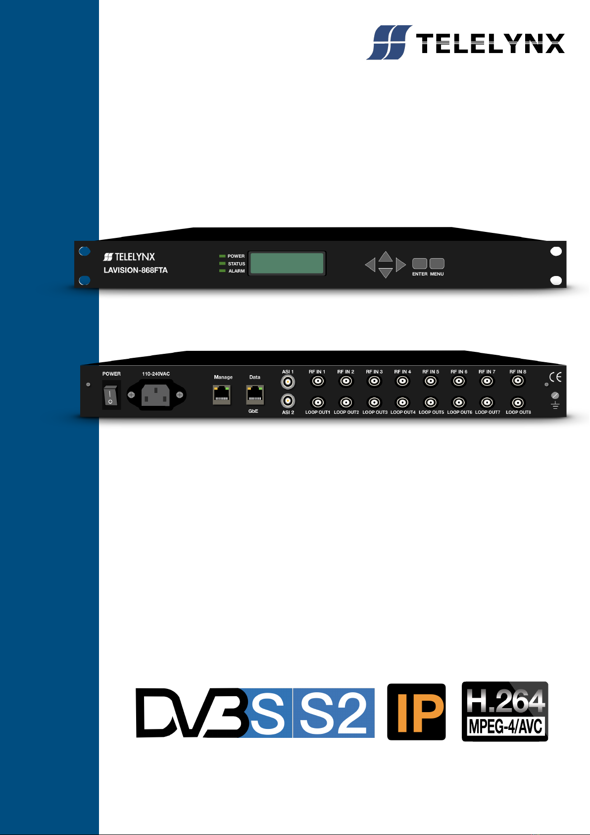
LAVISION-868FTA is a new generation ofRF-to-IP adapter, which can receive and demodulate eight
channels of DVB-S/S2,DVB-C and ISDB RF input signals, and then multiplex, scramble and process it
with channel coding. It adopts our newly developed functions such as “Module Management”, device
scrambling, and channel modulation. The flexible customization and high expansibility can satisfy the
user‟s current and future DTV system requirements.
The module management opens the scrambling function and configures the numbers of output
modulation channel through software authorization, as shown in the table below:
Item
Function
Remark
Level 1
PT+MUX
PT+MUX
Level 2
PT+MUX+1*CA scramble
PT+MUX+CA1
Level 3
PT+MUX+2*CA scramble
PT+MUX+CA2
Level 4
PT+MUX+3*CA scramble
PT+MUX+CA3
Level 5
PT+MUX+4*CA scramble
PT+MUX+CA4
The product is mainly applied to the DTV network head end room, edge of DTV backbone network, and
DTV branch head end room.
§1.2 Key Features
This product has the following key features:
Support eight RF inputs
14 TS-over-IP output
Two indenpendant ASI outputs
IP output data rate range: 1 ~ 800Mbps
Support RF signals output after demodulating, multiplexing, and scrambling via two ASI ports
Payload of UDP: 7 of 188-byte-length TS packets
Support processing for multiplexing, scrambling, PSI/SI
Scrambling up to 512 programs
Multiplexing up to 512 programs
Support auto-generation and manual upload for SI/PSI information
Support auto-generation and manual editing for network information, support upload of local
network segment
Support PID filtering, mapping and pass-through
Support PCR correction
Support DVB-CSA scrambling
Support up to 4 CAS simulcrypt
Maximum total EMM for 3Mbps, bandwidth cap for 1Mbps
188/204 TS packet length self-adaptive
Flexible configurations for data input/output to auto-detect the input TS

6
Support protocols of UDP,ARP, ICMP, and IGMP
Support HD/SD program transmitting
Support WEB/SNMP-based management
Support online remote upgrade
Language support: Chinese and English
Power failure memory recovery
Support device configuration import/export
Powerful background configuration and network management & monitoring
* Please refer to Annex A for detailed technical specifications.
§1.3 Front Panel
As shown in figure 1, there are one LCD display、one6-key keypad and three LED indicators on the front
panel of LAVISION-868FTA.
The model type and logo notification information will be displayed on the LCD screen during the device
initialization stage. User can check part of the working status of device, and set part of the parameters of
LAVISION-868FTAby exploring a menu realized by buttons/LCD screen after system initialization, see
section §3.3 for details.
The POWER LED will be light if the device powers on successfully.
The STATUS LED will show some working status of the device, see section§3.3 for details.
The ALARM LED will indicate warning messages of the device, if exists, see section §3.3 for
details.
Fig.1 Front Panel View of LaVision-868FTA
§1.4 Rear Panel
As shown in figure 2, the rear panel of LAVISION-868FTAconsists of one power supply connector, one
power switch, one management port, eight RF input ports, one eight IP output ports, and a grounding
point.
Power Input Port: To connect to 100~240V 50/60Hz AC input;
Power Switch: To turnLAVISION-868FTA on or off;
Management Port: RJ45 interface, to connect to management server via 100BaseT or Gigabit
Ethernet;
RF Input Port:F10-75J connector, to connect to satellite and microwave signals of LNB/MMDS
down converter;
Data Output Port:RJ45 interface, to connect to data destination equipments of
LAVISION-868FTA;
Grounding Point: To connect the device with conductive earth. Please make sure of proper

7
grounding of the device before start operating it for the safety of the operators and the device
itself!
Fig.2 Rear Panel View of LAVISION-868FTA
§1.5 Typical Application Architecture
Fig.3 System Application Block Diagram of LAVISION-868FTA
LAVISION-868FTA receives the standard DTV TS, please refer to section §3.3 for the format of TS.
The following devices may be able to provide input signal to LAVISION-868FTA
1.Satellite receiving antenna and MMDS down converter.
2.DVB-S/S2 modulator (often used to test environment)
The following devices may be able to receive the output signal of LAVISION-868FTA(Only TELELYNX®
products listed):
1.IDH2-3000 IP MUX/SCR/QAM series:this devices could make the multiplexer, scrambler, and
QAM modulation of UDP packet TS stream received from LAVISION-868FTA.
2.TX-6000 series IP Transcoder: provides a most powerful transcoding solution for producing live
video streams, supports multi-screen, multi-rate, multi-resolution, and multi-encoding models, helps
operators optimize high quality video content, and then transmits to Internet TV, mobile TV and PC
users.Besides, it supports real time bit rate switch and multi bit rate controlling output and provides
leading video quality.

8
§2 Before Use the Device
§2.1 Operation Requirements
In order to ensure proper operation of LAVISION-868FTA, there are some requirements for other digital
TV and network devices, which will connect withLAVISION-868FTA. Please see below for details:
§2.1.1 Requirements for Digital TV Devices
The RF output signals of the devices, which will provide signal source to or receive signal from
LAVISION-868FTA should comply withDVB-S/S2 modulation standard, and the input frequency range is
from 950MHz to 2150MHz.. The device which will receive output signal from LAVISION-868FTA, should
comply with
the following standards:
Transport Stream (TS): This means that the TS stream with one or more channels of digital TV, digital
audio broadcasting or any other digital TV services should comply with DVB standard; it must contain
PAT and PMT tables, which can completely describe the services.
The TS stream could be transmitted through ASI/Ethernet interface. For output IP interface, the TS
packets must be encapsulated into UDP datagram. Each output TS should have unique destination IP
address (unicast or multicast) and port number. The length of the UDP payload must be 7*188Byte (TS
packets), and the payload must be synchronized by sync byte 0x47.The TS stream (except the stream
with UDP format) also can be output fromASI interface, with standard format of 188 byte.
LAVISION-868FTA may be able to receive multiple transport streams from any devices with the TS
format complies with the above-mentioned format.
§2.1.2 Requirements for Network Devices
The switch used for the LAVISION-868FTAdata output and its destination devices (the IPQAM modulator
shown in figure 3)must be a Layer 3 gigabit switch, indispensability to support IGMP2.0. The backboard
exchange speed must be higher than 10Gbps; the maximum data exchange speed of each port must be
higher than 1000Mbps.
The switch for the LAVISION-868FTA and the managing workstation should be a 100M or gigabit switch,
the maximum data exchange speed of each port must be higher than 40Mbps. Normally, It can be the
same switch of data output,the two ports need to be configured to different VLANs.
Any hosts that may worsen the network traffic, such as some workstations or servers installed real-time
communication tools, streaming media server or WEB server, must not be located at the LAN switch of
the output of LAVISION-868FTA. These additional signals may cause packet loss, network jitter
worsening, and hence due to audio/video distortion at the audiences.
§2.2 System Requirements
Management workstation must have network connection and support TCP/IP protocol. Microsoft
Windows 2000/XP (or higher versions) and Internet Explorer 6.0 (or higher version) are the
recommended operating systems of the management workstation, and JavaScript must be supported by
the web browser.

9
§3 Operating the Device
§3.1 Quick Start
Please follow the procedures below if it is the first time for you to useLAVISION-868FTA for
constructingDTV head-end system:
1、Construct your hardware environment, including chassis installation, power supply system
deployment, and connecting switches, LAVISION-868FTA, the source device(s)(e.g. satellite
modulator or LNB module installed on satellite receiving antenna etc.), the destination device(s),
management workstation, and CAS server (refer to Fig. 3)
2、Plan for the IP addresses of management port and data output port, the cable connectors of
each source/destination devices; as well as number of digital TV transport streams. It is strongly
recommended to take note of device addresses, port numbers and other configurations and
keep them safely for checking purposes in future
3、Boot up each source devices of LAVISION-868FTA and configure the operating parameters, in
order to ensure the proper signal receiving/decoding of RF signals. Please refer to the user
manuals of source devices provided by their suppliers for detailed configuration.
4、Boot up LAVISION-868FTA. If you have known the management port IP address of the
LAVISION-868FTA you are currently using, and when it is in the same subnet with the
management workstation, you may also start configuring LAVISION-868FTA from the
management workstation directly. Otherwise you will need to configure the IP address of
management port using front panel control (refer to section §3.2.10.1)
5、Login to the web browser from the management workstation, key in the default user name
“admin” and password “000000”; add and configure usernames and passwords of users allowed
to access the device (refer to section0)
6、Configure the port number and IP address of LAVISION-868FTA data output (refer to section
§3.2.10.2)
7、Search for input programs tree (refer to section §3.2.5.1), configure the output program settings
of LAVISION-868FTA, including: select input program for output stream(refer to section, output
mode), output program parameter; configure the PID mapping parameters if needed (refer to
section).
8、If there are scrambled programs in the system, you need configure the CA operating parameters
as well. (refer to section).
9、Configure the destination devices of LAVISION-868FTA, to adjust the network settings, multiplex
& scramble settings and modulation settingsof IPQAM. Please refer to the user manuals of
succeeding devices provided by their suppliers for detailed configuration.
10、Make use of stream analyzer or set-top box to testthe system. If the device works properly and
the output signal can be received, then it is ready for transmission in the real network
§3.2 Web Management Operation of LAVISION-868FTA
The management and control of LAVISION-868FTAcan be done via a web browser. We recommend you
to use Internet Explorer 6.0 or higher version, and configure the display resolution to be (or higher than)
1024*768.

10
§3.2.1 Web User Login
After launching the Web browser, key in the IP address of LAVISION-868FTA‟s management port into
the Addressbar of Web browser. Embedded Web server of LAVISION-868FTAwill prompt with username
and password for authentication, as shown in the figure below:
Fig.4 Web Login
There is a factory default administrator user “admin” inLAVISION-868FTA with password of “000000”.
Please use this user and password to login to the system for the first time operation of
LAVISION-868FTA. But changing of password for this user is strongly recommended, and the new
password should be kept safely. If you choose “remember my proof”, you needn‟t input your user and
password when you login in the next time. But to ensure the safety, please do not choose this option in
the public server.
By default, the operation language of Web page is English. If you want to operate under the Chinese
interface, please select the „Simple Chinese” form the dropdown list. As shown in the figure below:
Fig.5 Web Guide
Fig.6 Dropdown List of Web Interface
After successfully logging into the system, browser will display the default page ofLAVISION-868FTA, as
shown in the figure below:

11
Fig.7 Default Page
In the default page, there are the information of device(model, serial number, etc), authorization state,
and some important specifications will be refreshed in real time. You could enter into the “device
monitoring”, “Input & Output”, “program multiplexing”, “program scrambling”, “device setting” page by
clicking different hyperlinks in the area of main-menu across the top of this page.
Remark: Device will not auto-save your parameters. If the device restarts, the
parameters will change to the state which you saved last time. If you have never
saved your parameters, all the parameters will change to the default state. So if you
want to save your own parameters, please click in lower right corner
after you finish setting LAVISION-868FTA.

12
§3.2.2 User Management
We recommend you to change the user and password after logging by the default user and password for
the safety. You can edit your user information in the user management page.
Click “device setting” in the home page, and then you have the device-setting page, as shown in the
figure below:
Fig.8 Device setting page
Click “user management” in the “select option” area on the left side of this page, and
then you have the user management page, as shown in the figure below:
Fig.9 User Management Page

13
In this page, you could add new user, edit old users‟ information or delete an user.
Remark: Only “admin” user could enter into the user management page.
§3.2.2.1 Add new user
In the area of “adding user”, input correctly users‟ user name and password, and confirm password.
Click “submit” button to complete add a new user. If you add successfully a new user, there will show
your user information on the right side, as shown in the figure below:
Fig.10 New user information
Remark: All new users are normal users. They are only permitted to set different parameters, but they
don‟t have the right to manage the other user or upgrade the system.
§3.2.2.2 Edit users‟ information
In the user information list in this page, you can edit an user by clicking the „modify‟ button in the same
row.
That makes you edit your password, as shown in the figure below:

14
Fig.11 Edit users information
In this bar, you can edit your user‟s password and that will be accomplish by clicking “submit”.
Remark: You could not delete the “admin” user, but you can change the password of this user.
When you use LAVISION-868FTA for the first time, you should change admin‟s password at first and
then save this password.
§3.2.2.3 Delete an user
In the user information list in this page, click the “delete” button in the same row to delete this user.
Remark: LAVISION-868FTA will not permit you to delete admin user but the normal user.

15
§3.2.3 Basic parameter setting
In the system setting page, click “basic setting” in the “select option” area
To enter basic parameter setting page, as shown in the figure below:
Fig.12 Basic parameter setting page
In this page, you could accomplish the setting of IP address, MAC address, set the IP address of time
synchronization server, open or close this service, and set the UTC time synchronization,etc.
§3.2.3.1 IP Settings
In the page of figure 11, input a right IP address in the “IP settings” bar, then click “submit” to set
LAVISION-868FTA‟ network parameter.
Remark: To ensure the working of device, you should guarantee that the management port IP address
and LAVISION-868FTA‟ management server IP are in the same network segment

16
§3.2.3.2 MAC setting
In the page of figure 11, input a right MAC address in the “MAC setting” bar, then click “submit” to set
LAVISION-868FTA‟ MAC address.
Remark: TELELYNX‟s products have the first 3 bytes “00:5C:B1” in the MAC address, that couldn‟t be
modified.
§3.2.3.3 Parameter setting about system clock
Set time synchronization server: In the page of figure 11, you can set IP address of network clock
server, auto synchronization time lag, auto synchronization switch in the “time synchronization protocol”
bar.
Remark: When you set a right network clock server address, LAVISION-868FTA will update his system
clock with the period which the user sets if SNTP service and network clock server are enabled.
Set system clock by manual operation: In the page of figure 11, you can set manually the system
clock in the “date/time(UTC)” bar. And you can also click ”get UTC time”, then click ”submit” button to
finish setting.
Remark:
1. If the network clock server address has already configured and enabled, and the SNTP server works
properly, the device will get the system clock from the network clock server, at this time, the manually
configured clock will be invalid.
2. The device will keep the system clock according to its internal circuit after each manually
configuration; this clock circuit can work properly over two years without the external power supply.
3. Select the synchro-browser UTC clock to be the standard UTC(0zone) clock, and this clock may be
different from the clock shown on server, e.g. if the server clock is UTC+8:00, the final clock will be
differ about 8 hours.

17
§3.2.4 Advanced Parameter setting
In the “system setting” page, click “Advanced setting” in the “select option” area
To enter the parameter setting page, as shown in the figure below:
Fig.13 Advanced setting page
In this page, you could import/export/reset the parameters, back-up/recover the parameters,
upgrade/back-up the software, import the authorization document, restart the device,etc.
§3.2.4.1 Import/export/reset the parameters
Import the parameters: In the page of figure 13, click “browse” button in the “inport/export/reset the
parameters” bar to choose the parameters‟ document, a .bin file, of the device.
Fig.14 Import/export/reset the parameters page
After choosing the parameters‟ document, click “Open” button. Then return to last page, click “import”
button, system will change the page to uploading management page,as shown in the figure below:

18
Fig.15 Document uploading management page
System will checkout the uploading document, if its format is right, there will appear mark in the
“uploading” bar and “document checkout” bar. Click “submit” button, you‟ll have this dialog box:
Click “YES” button to import the parameters.
Remark: 1. Please do not turn off the device or pull the power off when the device is importing the
parameters.
2. The device will restart after importing the parameters.
3.
Export the parameters: In the page of figure 13, click “export” button, it allows you to save parameter to
a file. Click “save” button to choose the path you wanted to save these parameters.
Reset the parameters: In the page of figure 13, click “reset” button, then you‟ll have this dialog box:

19
§3.2.4.2 Backup/Restore the parameters
Back-up the parameters: In the page of figure 15, there is a “Parameter Back-up/Restore” bar:
Fig.16 Parameter back-up/recover
Fill in the parameter description information in the “Enter Description"field, (just like 2012-10-26), click
“Backup” button, you‟ll have this dialog box:
Click ”YES” button, system will create a new back-up parameter document in the device.
Remark: System could only save a unique back-up document each time, the new back-up document will
cover the last one.
Restore the parameters: When the device has a back-up document, click “Restore” button, you‟ll have
this dialog box:
Click “YES” button to import the parameters.
§3.2.4.3 Upgrade/Backup the software
As shown in the figur12, you e can choose the upgrade document in the “Software Upgrade/Export” bar,
then import it to upgrade the device.
Click “Browse” button, you‟ll have this dialog box:
Select the upgrade document, it is a .bin file from Telelynx, click “Open” button, as shown below:

20
Click “Upgrade” button, system will change the page to uploading management page, as shown below:
Fig.17 Document uploading management page
System will checkout the uploading document, if its format is right, there will appear mark in the
“Uploading” bar and “document checkout” bar. Click “Submit” button, you‟ll have this dialog box:
Click “YES” button to upgrade the device.
After upgrading, you can check the device version information in the “device information” bar.
Remark:
Table of contents
Other TELELYNX Media Converter manuals