TELEMED UAB ArtUs EXT-1H User manual
Rev.2.7
ArtUs EXT-1H / ArtUs OEM-1H
Ultrasound Diagnostic System
I/O MODULE USER GUIDE

ArtUs Synchronization User Guide
- 2 -
Contents
1. Terms Used In This Guide........................................................................3
2. I/O Module Connectors Description ..........................................................3
3. I/O Module Triggering Signals Description................................................4
4. ArtUs Sync Options Utility.........................................................................6
5. Voltage Levels for Interface Signals .........................................................8
6. Signal Diagrams .......................................................................................9
7. External Equipment Connection Diagram ...............................................11
8. Return to normal scan mode ..................................................................11
9. How to enable/disable I/O signals without ArtUs Sync Options Utility .....11
10. Twin Synchro ArtUs Setup...................................................................... 12
Configuration 1: 2 ArtUs, 2 PCs, Signal Generator for external frame synchronization .. 12
Configuration 2: 2 ArtUs, PC with 2 Monitors, Signal Generator for external frame
synchronization ............................................................................................................... 14
Setting the highest frame rate ......................................................................................... 16
11. Q&A Section...........................................................................................17
12. Revision History......................................................................................18

ArtUs Synchronization User Guide
- 3 -
Introduction
ArtUs beamformer can be equipped with additional I/O module which allows controlling it
using an external signal providing device, such as signal generator. I/O module provides
several coaxial cable connectors used for getting input and providing output signals. ArtUs
with I/O module installed can be used in various scenarios of getting ultrasound images
which are described later in this document.
1. Terms Used In This Guide
Line (Ultrasound Line) –a set of ultrasound echo signals acquired as a result of one
transmission event.
Frame (Ultrasound Frame) –a set of ultrasound lines combined together and displayed
simultaneously.
ScanStart –signal that triggers the state of beamformer between FREEZE and SCAN.
2. I/O Module Connectors Description
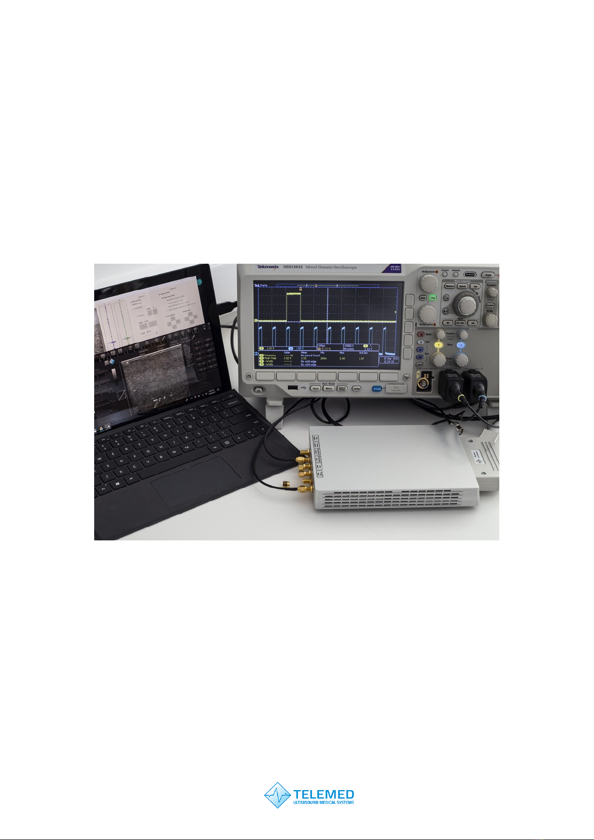
ArtUs EXT-1H with I/O module installed looks like shown on a picture below (rear view), cooling
fans “looking” down, see attached photo. Connectors are of SMA female type and require 50 Ohm
coaxial cable equipped with SMA male plug on beamformer end.
Connectors are labeled as shown in a table:
Line
output
Frame
output
ScanStart
output
ScanStart
input
Line
input
Frame
input
The names and designation of connectors:
A) Ultrasound Line Output (label Line output) signal, a falling edge of the output signal
corresponds to start of ultrasound data acquiring from a tissue for one ultrasound line.
Signal stays in logic level "0" at the end of the line
B) Ultrasound Frame Output (label Frame output) signal, a falling edge of the output signal
corresponds to start of ultrasound data acquiring from a tissue for one ultrasound frame.
Signal returns to logic level "1" at the end of the frame
C) ScanStart output signal, system generates logic level "0" in FREEZE state and logic level
"1" in SCAN state. This signal is not configurable
D) ScanStart input signal, system changes state from FREEZE to SCAN and from SCAN to
FREEZE at each rising edge of the input signal (works like FREEZE button). This signal is
not configurable

ArtUs Synchronization User Guide
- 4 -
E) Ultrasound Line Input (label Line input) signal, upon receiving a rising edge of the input
signal system starts acquiring of ultrasound data from a tissue for one ultrasound line with
delay of approximately 20 us
F) Ultrasound Frame Input (label Frame input) signal, upon receiving a rising edge of the
input signal system starts acquiring of ultrasound data from a tissue for one ultrasound
frame with delay of approximately 20 us.
ArtUs OEM-1H with I/O module has the same set of connectors labeled as shown in the table
below:
Line
output
Frame
output
ScanStart
output
ScanStart
input
Line
input
Frame
input
3. I/O Module Triggering Signals Description
Signal
Trigger
SCAN state
FREEZE
state
Final
State
Line Input
Rising Edge
Acquire one line
delay 20 us
n/a
Logical 0
Line Output
Falling Edge
Acquired one line
n/a
Logical 0
Frame Input
Rising Edge
Acquire set number
of frames
delay 20 us
n/a
Logical 0
Frame Output
Falling Edge
Acquired set number
of frames
n/a
Logical 1
ScanStart Input
Unconfigured (FREEZE
button simulation)
Rising Edge
To FREEZE
To SCAN
Logical 0
ScanStart Input
Configured
n/a
Logical 1
Logical 0
n/a
ScanStart Output
Device state
Logical 1
Logical 0
n/a
Ultrasound Line input and Ultrasound Frame input signals require to be configured by ArtUs
Sync utility:

ArtUs Synchronization User Guide
- 5 -
•Ultrasound Line input - system starts acquiring of ultrasound data from tissue for
one ultrasound line approximately in 20 us after rising edge of the signal
•Ultrasound Frame input - system starts acquiring of ultrasound data from tissue for
one ultrasound frame approximately in 20 us after rising edge of the signal
Ultrasound Line output and Ultrasound Frame output works automatically, not require
additional configuring:
•Ultrasound Line output - falling edge of the input signal corresponds to start of
ultrasound data acquiring from tissue for one ultrasound line. Signal stays in logic level "0" at
the end of line
•Ultrasound Frame output - falling edge of the input signal corresponds to start of
ultrasound data acquiring from tissue for one ultrasound frame. Signal returns to logic level
"1" at the end of frame
ScanStart input and ScanStart output without additional configuring:
•ScanStart input - system changes state from FREEZE to SCAN and from SCAN to
FREEZE at each rising edge of the signal (works like FREEZE button)
•ScanStart output - system generates logic level "0" in Freeze mode and logic level
"1" in scan mode
ScanStart input and ScanStart output with additional configuring:
•ScanStart input - system scans during logic level "1" and does pause (not equal
FREEZE) of scanning during logic level "0". Ultrasound Line output is synchronized with
ScanStart input
•ScanStart output - system generates logic level "0" in Freeze mode and logic level
"1" in scan mode

ArtUs Synchronization User Guide
- 6 -
4. ArtUs Sync Options Utility
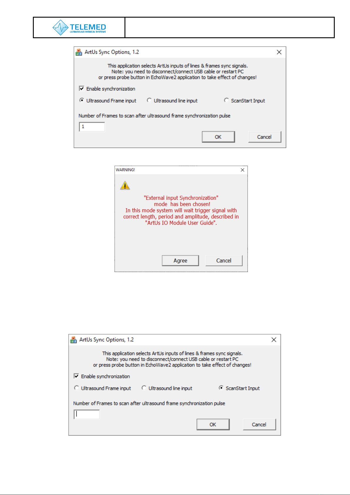
1. Run ArtUs Sync Options utility in Administrator mode, select Ultrasound Line input
synchronization mode, see picture below.
Please note, after clicking “OK” button user gets warning message as shown below.
To activate device settings user needs to run EchoWave II program or if EchoWave II is
already running –to push “Probe”button.
2. Run ArtUs Sync utility in Administrator mode, select Ultrasound Frame input
synchronization mode, see picture below. “Number of Frames to scan after synch pulse”
define, how many frames will be received after each “Ultrasound Frame Input” signal. Set
“0” to start non-stop scanning after rising edge of “Ultrasound Frame Input” signal.
ArtUs Synchronization User Guide
- 7 -
Please note, after clicking “OK” button user gets warning message as shown below.
To activate device settings user needs to run EchoWave II program or if EchoWave II is
already running –to push “Probe”button.
3. Run ArtUs Sync utility in Administrator mode, select ScanStart Input synchronization
mode, see picture below.
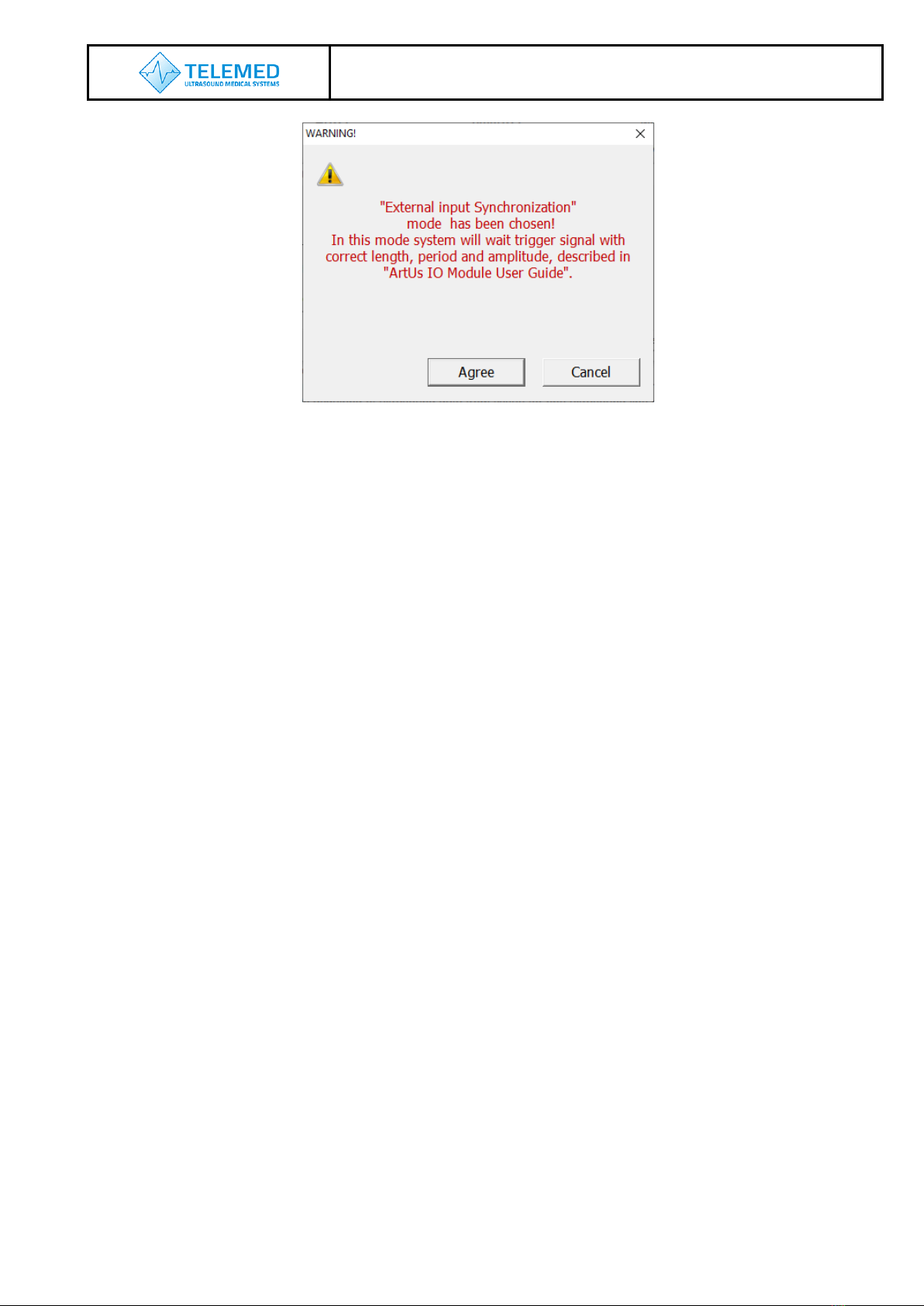
Please note, after clicking “OK” button user gets warning message as shown below.
ArtUs Synchronization User Guide
- 8 -
To activate device settings user needs to run EchoWave II program or if EchoWave II is
already running –to push “Probe”button.
Note: Ultrasound Frames have one additional “passive” ultrasound line when any of inputs
is chosen in ArtUs Sync Options utility.
5. Voltage Levels for Interface Signals
•Input signals –2,5V or 3,3V CMOS level (5V logic tolerance)
•Output signals –3,3V CMOS level
ArtUs Synchronization User Guide
- 9 -
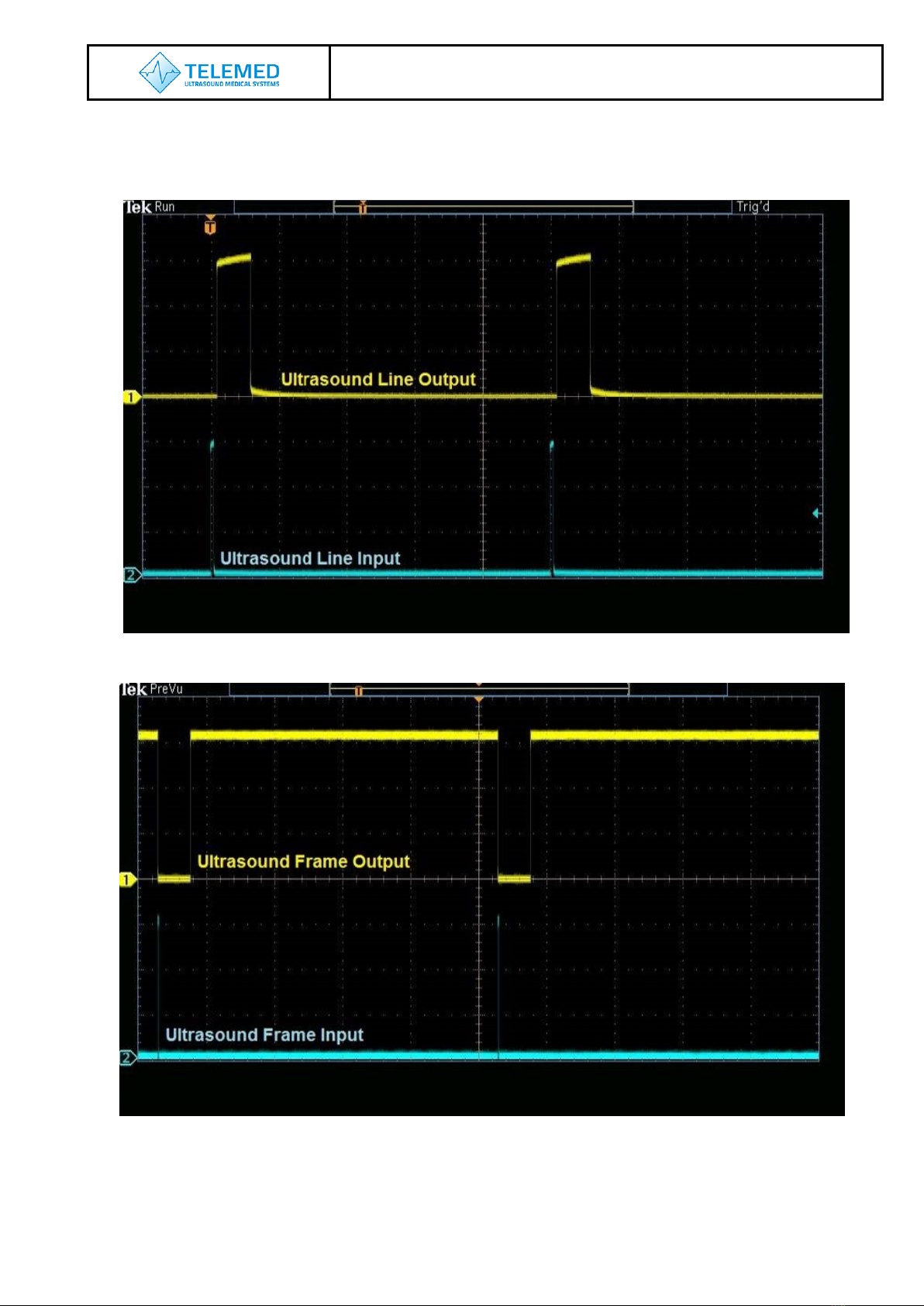
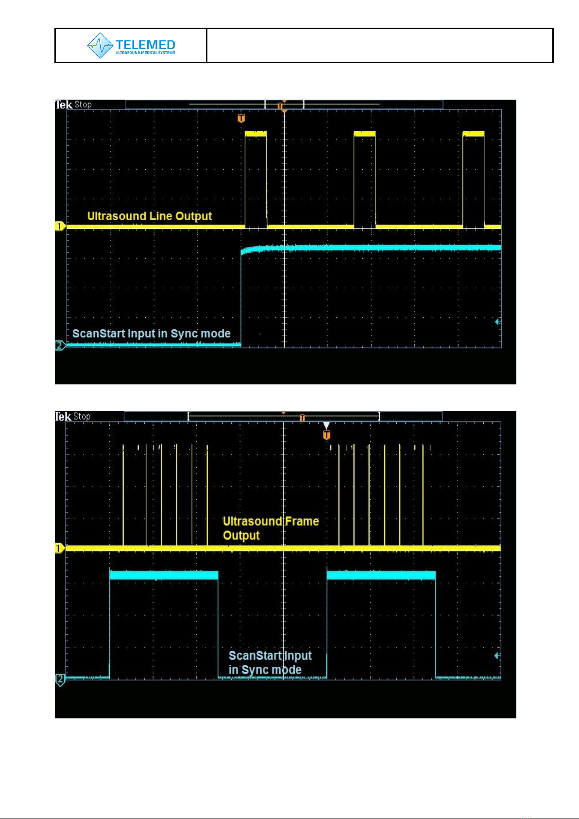
6. Signal Diagrams
Diagrams show external equipment input signals and corresponding outputs.
Ultrasound Line Input vs Ultrasound Line Output
Ultrasound Frame Input vs Ultrasound Frame Output
ArtUs Synchronization User Guide
- 10 -
ScanStart Input in Sync Mode vs Ultrasound Line Output
ScanStart Input in Sync Mode vs Ultrasound Frame Output

ArtUs Synchronization User Guide
- 11 -
7. External Equipment Connection Diagram
Block schematics below demonstrates how ArtUs inputs must be connected to external equipment
outputs.
8. Return to normal scan mode
To switch ArtUs scanner back to normal scan mode do not forget to run ArtUs Sync utility in
Administrator mode, clear checkbox Enable synchronization and click “OK” button. Please
note, after clicking “OK” button user needs to disconnect/reconnect USB cable.
9. How to enable/disable I/O signals without ArtUs Sync Options Utility
Run Registry Editor utility (regedit.exe)
Locate Registy path:
„HKEY_LOCAL_MACHINE\SYSTEM\CurrentControlSet\services\ArtUs\Parameters".
To Enable synchronization and enable Ultrasound Frame input
Write value 1to "External synch mode“ register
To Enable synchronization and enable Ultrasound Line input
Write value 2to "External synch mode“ register
To Enable synchronization and enable ScanStart output
Write value 4to "External synch mode“ register
To define Number of Frames to scan after ultrasound frame synchronization pulse
Write number of frames to "Synch frames number“ register
ArtUs
External equipment
+2.5…+5V
Input
R

ArtUs Synchronization User Guide
- 12 -
10. Twin Synchro ArtUs Setup
Some ultrasound applications require synchronous work of two or more beamformer
devices. You can use ArtUs system in such scenarios. There can be several possible
configurations which are described below.
To use external hardware Freeze/Run button, edit a line shown below and save
options2.txt file (located in C:\Program Files (x86)\TELEMED\Echo Wave II\Config\Options
directory):
accept_ultrasound_keyboard_commands_when_window_is_not_focused;1
Configuration 1: 2 ArtUs, 2 PCs, Signal Generator for external frame synchronization
Figure 1 Twin ArtUs with 2 PCs
Configuration 1 setup:
1. Connect both ArtUs beamformers to their respective PCs using USB 3.0 or higher
ports
2. Connect Signal Generator to both ArtUs devices as shown on Figure 1 Twin ArtUs
with 2 PCs using 50 Ohm coaxial cables and appropriate connectors. ArtUs has
SMA50 connectors for coaxial cable attachment

ArtUs Synchronization User Guide
- 13 -
3. Connect hardware Freeze/Run button to ScanStart Inputs of both ArtUs devices as
shown on Figure 1
4. Run ArtUs Sync Options.exe utility on each PC
5. Check Enable Synchronization and select Ultrasound Frame Input
6. Push OK button. Now both ArtUs devices are in external synchronization mode
7. Set Signal Generator to pulse triggering with frequency depended on probe and
scanning parameters (number of probe elements, depth, line density and other,
which fluence on ultrasound frame time)
8. Run Echo Wave II program on each PC
9. To get synchronous Cine files, do the next steps:
9.1. Turn OFF generator
9.2. Click Freeze button on Echo Wave II on each PC or press hardware
Freeze/Run button to stop scanning
9.3. Click Freeze button on Echo Wave II on each PC or press hardware
Freeze/Run button to start scanning
9.4. Turn ON generator
9.5. Perform scanning
9.6. Turn OFF generator
9.7. Click Freeze button on Echo Wave II on each PC or press hardware
Freeze/Run button to stop scanning
9.8. Save Cine clips as “avi” files on both Echo Wave instances
Note: Signal Generator can run continuously. In this case captured frames at two
PCs may be shifted one or more frames relatively to each other.

ArtUs Synchronization User Guide
- 14 -
Configuration 2: 2 ArtUs, PC with 2 Monitors, Signal Generator for external frame
synchronization
Figure 2 Twin ArtUs with a PC and optional external monitor (Frame Input)
Configuration 2 setup:
1. Connect both ArtUs beamformers to PC using two USB 3.0 or higher ports
2. Connect Signal Generator to both ArtUs devices as shown above using 50 Ohm
coaxial cables and appropriate connectors. ArtUs has SMA50 connectors for
coaxial cable attachment
3. Connect hardware Freeze/Run button to ScanStart Input of one of ArtUs devices as
shown on Figure 2
4. Run ArtUs Sync Options.exe utility
5. Check Enable Synchronization and select Ultrasound Frame Input
6. Push OK button. Now both ArtUs devices are in external synchronization mode.
7. Set Signal Generator to pulse triggering with frequency depended on probe and
scanning parameters (number of probe elements, depth, line density and other,
which fluence on ultrasound frame time).
8. Run two Echo Wave II instances. Use each monitor to display one Echo Wave II
window. Chose active probe for each instance

ArtUs Synchronization User Guide
- 15 -
9. Run CopyData.exe utility (located in C:\Program Files (x86)\TELEMED\Echo Wave
II\Config\Plugins\CopyData directory)
10.To get synchronous Cine files, do the next steps:
10.1. Turn OFF generator
10.2. Click Freeze/Run button on CopyData.exe utility window or press hardware
Freeze/Run button to stop scanning
10.3. Click Freeze button on CopyData.exe utility window or press hardware
Freeze/Run button to start scanning
10.4. Turn ON generator
10.5. Perform scanning
10.6. Turn OFF generator
10.7. Click Freeze button on CopyData.exe utility window or press hardware
Freeze/Run button to stop scanning
10.8. Save Cine clips as “avi” files on both Echo Wave instances
Note: Signal Generator can run continuously. In this case captured frames at two
PCs may be shifted one frame relatively to each other.

ArtUs Synchronization User Guide
- 16 -
Setting the highest frame rate
To set the maximum possible frame rate rase slowly triggering frequency on Signal
Generator. At the same time monitor the frame rate shown in Echo Wave II ultrasound
window. Both frequencies should change accordingly. When you reach maximum frame
rate you will see dramatic frame rate drop (approximately 2 times) in Echo Wave II. Adjust
the frequency a little to lower value to regain frame rate in Echo Wave II window as shown
on Signal Generator. Now you reached the maximum frame rate for current scanning
settings.
Achievable result example:
You can reach up to 150 frames per second with the following settings:
•128 element transducer
•Scan depth: 40 mm
•Line density: Standard
•Number of focuses: 1
NOTE: If you need other scanning parameters the achievable frame rate can be different.
In this case you will need to adjust triggering frequency.

ArtUs Synchronization User Guide
- 17 -
11. Q&A Section
Q: Where can I purchase needed cables for I/O module connection?
A: You can purchase ready to use cables at Amazon, see example link.
Q: Is it possible to achieve higher frame rates than in your example case?
A: Yes, you can. To get higher frame rates you can:
•Lower Line Density
•Make smaller View Area
•Lower number of Focuses
•Lower Scan Depth
Q: Can I run two EchoWave II instances with two beamformers attached to one computer?
A: Yes, you can. To run two instances of Echo Wave II application follow these steps:
1. Find options2.txt file in C:\Program Files (x86)\Telemed\Echo Wave
II\Config\Options\
2. Open it with notepad.exe
3. Set parameter: allow_scanning_by_all_software_instances;1 (replace “0” with
“1”)
4. Save and close file options2.txt
5. Run Echo Wave II application
6. Open Menu->Tools->Options
7. Select tab Technical
8. Set checkbox Allow to start several software instances
9. Shutdown Echo Wave II application
10.Attach two beamformers to the same computer using different USB ports
11.Start Echo Wave II application and allow it load completely
12.Start another instance of Echo Wave II application
13.On both instances you should see live images from one of attached
beamformer/transducer sets. You Probe button to choose another transducer.

ArtUs Synchronization User Guide
- 18 -
12. Revision History
Revision
Revision
Date
Description of Revision
Revision Author
1.0
2018.07.17
Initial Release
A. Prysiazhniuk
1.1
2018.07.19
Was added photo of rear panel
G. Volkov
1.2
2018.07.24
Added additional description
G. Volkov
1.3
2019.04.10
Added chapter 6.
A. Prysiazhniuk, G.
Volkov
1.4
2019.05.07
Mistakes fixes
A. Prysiazhniuk
2.0 –2.5
2020.02.05
–
2020.12.18
Chapters 9, 10, 11 edited. Small typo
fixes
A.Kovalev
2.6
2020.01.12
Edited chapters 2, 3, 4. Added chapter
12
A. Prysiazhniuk
2.7
2021.03.18
Updated Sync Options Utility
description - Chapter 4
A.Kovalev
This manual suits for next models
1
Table of contents
Other TELEMED UAB Diagnostic Equipment manuals


