Telemotive AG blue PiraT2 User manual
Remote Control Touch
User Guide
Version 2.1.1 / 08.12.2015

Remote Control Touch
User Guide
Datum: 08.12.2015
Seite 2 von 61
RCTouch_UserGuide_V2.1.1.doc
Table of contents
1LICENSE AGREEMENT.....................................................................................................4
2PRODUCT LIABILITY.........................................................................................................5
3Overview ............................................................................................................................6
4System requirements........................................................................................................7
5Maintenance provisions and safety regulations .............................................................8
5.1 Operating conditions...................................................................................................8
5.1.1 Temperature......................................................................................................8
5.1.2 Condensation....................................................................................................8
5.1.3 Environment......................................................................................................8
5.1.4 Mechanical action..............................................................................................9
5.2 Assembly....................................................................................................................9
5.2.1 Cable sets.........................................................................................................9
5.2.2 Mounting ...........................................................................................................9
5.2.3 Positioning of antenna.......................................................................................9
5.3 Proper operation.......................................................................................................10
6Data sheet........................................................................................................................11
7Device...............................................................................................................................12
7.1 Position of components............................................................................................12
7.1.1 Top view..........................................................................................................12
7.1.2 Side view, from the right..................................................................................13
7.1.3 Rear side.........................................................................................................13
7.2 Functionality of components.....................................................................................14
7.2.1 Ports................................................................................................................14
7.2.2 Brightness sensor............................................................................................14
7.2.3 Home button....................................................................................................14
7.2.4 Speaker...........................................................................................................14
7.2.5 LEDs...............................................................................................................15
7.2.6 Microphone .....................................................................................................15
7.2.7 Touchscreen ...................................................................................................15
7.3 Accessories..............................................................................................................15
7.4 Installation................................................................................................................16
7.4.1 Cable connection.............................................................................................16
7.4.2 Client...............................................................................................................17
8Surface.............................................................................................................................19
8.1 Layout of the views...................................................................................................19
8.1.1 Header bar......................................................................................................20
8.1.2 Tab bar............................................................................................................21
8.2 Applications..............................................................................................................21
8.3 Tab sheets ...............................................................................................................22
8.3.1 Overview.........................................................................................................22
8.3.2 *Device name n*..............................................................................................22
8.3.3 Functionkeys...................................................................................................23
8.3.4 Markerlist.........................................................................................................24
8.3.5 CAN/Serial/LIN/Ethernet/Camera/CCP_XCP ..................................................24
8.3.6 MOST150........................................................................................................24
8.3.7 GPS ................................................................................................................25
8.3.8 General...........................................................................................................26
8.4 Displays....................................................................................................................28
8.5 Other views ..............................................................................................................30
8.5.1 AlertDialog.......................................................................................................30
8.5.2 FW-Update......................................................................................................30
8.5.3 Launcher.........................................................................................................30
8.5.4 RC Monitor......................................................................................................31

Remote Control Touch
User Guide
Datum: 08.12.2015
Seite 3 von 61
RCTouch_UserGuide_V2.1.1.doc
8.5.5 RC Text...........................................................................................................32
8.5.6 Standby...........................................................................................................33
8.6 Restrictions in standalone mode...............................................................................33
8.6.1 RCTouch applications.....................................................................................33
8.6.2 Client applications...........................................................................................33
9Operation .........................................................................................................................36
9.1 Adjusting backlight ............................................... Fehler! Textmarke nicht definiert.
9.1.1 Automatic adjustment.................................. Fehler! Textmarke nicht definiert.
9.1.2 Manual adjustment...................................... Fehler! Textmarke nicht definiert.
9.2 Adjusting volume.................................................. Fehler! Textmarke nicht definiert.
9.3 Changing application............................................ Fehler! Textmarke nicht definiert.
9.4 Changing tab sheet .............................................. Fehler! Textmarke nicht definiert.
9.5 Opening and closing side menu ........................... Fehler! Textmarke nicht definiert.
9.6 Playing voice note................................................ Fehler! Textmarke nicht definiert.
9.7 Scrolling through tab sheet................................... Fehler! Textmarke nicht definiert.
9.8 Setting and deleting complex triggers................... Fehler! Textmarke nicht definiert.
9.9 Setting triggers..................................................... Fehler! Textmarke nicht definiert.
9.9.1 Trigger with voice note ................................ Fehler! Textmarke nicht definiert.
9.9.2 Trigger without voice note ........................... Fehler! Textmarke nicht definiert.
9.10 Actuating function key ..............................................................................................44
9.11 Adjusting backlight ...................................................................................................45
9.11.1 Automatic adjustment...............................................................................45
9.11.2 Manual adjustment...................................................................................45
9.12 Adjusting volume......................................................................................................45
9.13 Changing application................................................................................................46
9.14 Changing tab sheet ..................................................................................................46
9.15 Opening and closing side menu ...............................................................................46
9.16 Playing voice note....................................................................................................47
9.17 Scrolling through applications...................................................................................47
9.18 Scrolling through tab bar ..........................................................................................48
9.19 Scrolling through tab sheet.......................................................................................48
9.20 Setting and deleting complex triggers.......................................................................48
9.21 Setting triggers.........................................................................................................51
9.21.1 Trigger with voice note..............................................................................51
9.21.2 Trigger without voice note.........................................................................52
9.22 Switching off device..................................................................................................52
9.23 Switching on device..................................................................................................53
9.24 Updating firmware ....................................................................................................53
10 Abbreviations ..................................................................................................................57
11 List of figures...................................................................................................................58
12 List of tables....................................................................................................................59
13 Version history ................................................................................................................60
14 Contact.............................................................................................................................61

Remote Control Touch
User Guide
Datum: 08.12.2015
Seite 4 von 61
RCTouch_UserGuide_V2.1.1.doc
1 LICENSE AGREEMENT
Please read the license agreement of this license contract carefully, before you install the soft-
ware. By the installation of the software you agree to the conditions of this license contract.
This software-license agreement, in the following called “license”, contains all rights and re-
strictions for final users that regulate the use of the accompanying software, operating instruc-
tions and other documents, in the following called as “software”.
1. This license contract is an agreement between licensor and licensee, who is being licensed to
use the named software.
2. Licensee acknowledges that this is only a limited nonexclusive license. This means, that the li-
censee has no right to allocate sublicenses. Licensor is and remains the owner of all titles, rights
and interests in the software.
3. The software is a copyright property of the Telemotive AG. The program or parts of it may not be
further licensed to third parts, rented, sold or be further marketed in any form without explicit writ-
ten approval by Telemotive AG. The user may neither change the software and their compo-
nents, nor modify, nor redevelop or decompile otherwise in any form.
4. This software is subject to no warranty. This software is sold as is, without any warranty. If at any
time, a user changes his system, we hold no responsibility to change our software to make it
work again.
5. This license permits licensee to install the software on more than one computer system, as long
as the software will not be used on more than one computer system simultaneously. Licensee will
not make copies of the software or allow copies of the software to be made by others, unless au-
thorized by this license agreement. Licensee may make copies of the software for backup pur-
poses only. Licensee is not entitled to transmit or to transfer the software or its rights from this
license agreement.
6. Licensor is not liable to licensee for any damages, including compensatory, special, incidental,
exemplary, punitive or consequential damages, connected with or resulting from this license
agreement or licensee’s use of this software.
7. Licensee agrees to defend and indemnify licensor and hold licensor harmless from all claims,
losses, damages, complaints or expenses connected with or resulting from licensee’s business
operations.
8. Licensor has the right to terminate this license agreement and licensee’s right to use this software
upon any material breach by licensee. The duration of the license contract is indefinitely deter-
mined.
9. Licensee agrees to return all copies of the software to licensor or to destroy them upon termina-
tion of the license contract.
10. This license agreement replaces and supersedes all prior negotiations, dealings and agreements
between licensor and licensee regarding this software.
11. This license contract is subject to German law.
12. If a regulation of this license contract is void by law, the validity of the remaining regulations is not
affected. If there is such a regulation it will be replaced by a valid, according to the legal regula-
tions and enforceable regulation with similar intention and similar economic consequence.
13. The license contract is effective by delivery of the software of the licensor to the licensee and/or
by usage of the software by the licensee. This license contract is also valid without licensor’s sig-
nature.
14. The license automatically goes out if the licensee does not agree to the license regulations de-
scribed here or offend against the license regulations of this license contract. With ending the li-
cense contract the licensee is obliged to extinguish or to destroy the software and all copies of it
no matter if installed or stored on disk or to hand all of it back to Telemotive AG.
15. The licensee is liable for all damages caused to the licensor by the violation of these license
regulations.

Remote Control Touch
User Guide
Datum: 08.12.2015
Seite 5 von 61
RCTouch_UserGuide_V2.1.1.doc
2 PRODUCT LIABILITY
For all offers, sales and supplies the following conditions apply exclusively, even if the buyer,
orderer and suchlike prescribes other conditions. Alterations are only valid, if they are agreed in
writing.
1. The technical documentation is part of the products. The product liability and the product guaran-
tee will be excluded, if contents and in particular the safety references and instructions of the
documentation are not considered.
2. The products do belong to the group of test tools. By application of the equipment a disturbance
of the tested system cannot be completely excluded. For this reason, the warranty of a perfectly
functioning system cannot be taken over by the manufacturer. Application of the product takes
place at one’s own risk.
3. The liability of the substitution of damages according to §1 product liability law is expressly ex-
cluded in the context of §9 product liability law, as far as compelling legal terms do not provide
anything else.
4. In no event will the producer be liable for any indirect, incidental, special or consequential dam-
ages, including loss of profits, loss of revenues, loss of data, loss of use, any other economic ad-
vantage or damage caused by pretensions of third party towards the customer out of this
agreement, under any theory of liability, whether in an action in contract, strict liability, tort (includ-
ing negligence) or other legal or equitable theory.
5. The burden of proof is with the customer.
6. The Telemotive AG does ensure the legal warranty according to German law. Except for warran-
ties expressly set forth in this agreement, any and all products are delivered “as is” and the pro-
ducer makes and the customer receives no additional express or implied warranties. The
producer hereby expressly disclaims any and all other warranties of any kind or nature con-
cerning the products, whether express or implied, including without limitation, any warranty of ti-
tle, merchantability, quality, accuracy or fitness for a particular purpose or the customer’s
purpose. The producer expressly disclaims any warranties that may be implied from usage of
trade, course of dealing or course of performance. Except for the express warranties stated in
this agreement the products are provided with all faults and the entire risk of unsatisfactory quali-
ty, performance, accuracy. The possible effort is with the customer. The producer does not war-
rant that the products will operate without interruption or be error free.
7. The Telemotive AG is justified to exchange defective goods against homogeneous acceptable
ones or to eliminate the fault within an appropriate period. In this case a demand for redhibitory
action or reduction of price expires. Warranty claims presuppose a due notice of defects.
8. Resale, transfer, donation, exchanges or the rental of the offered products at third party is permit-
ted without clearance of the Telemotive AG.
9. German Law is deemed to be as legal basis.
© by Telemotive AG, 2015
Subject to errors and to technical changes as part of product improvement.

Remote Control Touch
User Guide
Datum: 08.12.2015
Seite 6 von 61
RCTouch_UserGuide_V2.1.1.doc
3 Overview
This user guide describes the administration of the Remote Control Touch (hereinafter referred
to as RCTouch), the surface of the installed software and its operation.
The configuration of the RCTouch was only tested with Microsoft®Windows®7.
This document refers to blue PiraT Mini firmware version 02.02.01 and the Telemotive Sys-
tem Client version 2.2.1. Some features depend on model and feature license or may not be
available in older versions.
Software updates and user guides for other, optional, licensed enhancements are available in
the Telemotive ServiceCenter. (You will find the address under Contact).
To ensure the most reliable operation of your system as possible, please make sure to use al-
ways current firmware and software versions.
Index

Remote Control Touch
User Guide
Datum: 08.12.2015
Seite 7 von 61
RCTouch_UserGuide_V2.1.1.doc
4 System requirements
Control Unit
A Laptop or a PC is used to configure the devices by a software client. It also allows to save the
recorded data and to use them offline.
blue PiraT2 / blue PiraT Mini
The blue PiraT Mini is the newest and very small datalogger which was developed by Telemo-
tive AG. The blue PiraT2 is his preceding model with enhanced features.
The communication of bus systems and control units are monitored and relevant data can be
recorded very precisely with the data loggers of the Telemotive AG. The collected data are
stored on the data logger and can be downloaded via Ethernet and, e.g., analyzed on a test
computer.
Telemotive System Client
The software client for the blue PiraT2, blue PiraT2 5E and blue PiraT Mini, the TSL client
(Telemotive System Link), is needed to configure the data logger and later to download or con-
vert the recorded data.
Further applicable manuals
Beside this user guide the Telemotive AG offers the main manuals for the client as well as for
the different data logger generations in its ServiceCenter at https://sc.telemotive.de/bluepirat.
User manual for the Telemotive System Client
https://sc.telemotive.de/4/uploads/media/TelemotiveSystemClient_UserManual.pdf
User manual for blue PiraT2 / blue PiraT2 5E
https://www.telemotive.de/4/uploads/media/blue_PiraT2_UserManual.pdf
User manual for blue PiraT Mini
https://www.telemotive.de/4/uploads/media/blue_PiraT_Mini_UserManual.pdf
Licensed enhancements have own manuals which are stored in the ServiceCenter too. You will
find a list of these enhancements in the user manuals in the chapter Additional features by
optional licenses.
Index

Remote Control Touch
User Guide
Datum: 08.12.2015
Seite 8 von 61
RCTouch_UserGuide_V2.1.1.doc
5 Maintenance provisions and safety regulations
Note according to standard EN55011:2009
The device is used in an industrial environment. Due to the occurring, conducted as well as ra-
diated disturbances it possibly can be difficult to ensure electromagnetic compatibility in other
environments.
Cleaning
The device may only be cleaned with a clean cloth slightly dampened with water. Other cleaning
agents such as gasoline, alcohol, etc., may not be used.
Maintenance
The device is maintenance-free. The case must not be opened by the customer. Unauthorized
modifications will void the warranty.
In case of failure, the customer may change the fuse on the cable set or fuses accessible from
outside only. The fuse may only be replaced with a fuse of the same type and nominal current
rating.
Storage
The device may only be stored within a temperature range of - 40 °F to + 185 °F.
Disposal
Disposal of the device must be in accordance with the statutory regulations.
5.1 Operating conditions
5.1.1 Temperature
The device must not be operated outside the specified temperature range. Adequate ventilation
must be ensured. The device must not be placed too close to walls or other devices. The device
must not be stacked with other components on each other unless proper ventilation is ensured
and the device is to be operated at an ambient temperature of more than 77 °F.
5.1.2 Condensation
The device must not be switched on immediately when brought from cold ambient conditions
into a room with normal ambient conditions.
5.1.3 Environment
The device must not be used outdoors or in adverse ambient conditions such as moisture, high
humidity or dust. Operation of the device is further not allowed in an environment with flamma-
ble or explosive gases.
Index

Remote Control Touch
User Guide
Datum: 08.12.2015
Seite 9 von 61
RCTouch_UserGuide_V2.1.1.doc
5.1.4 Mechanical action
Altitude: - 300 to + 5500 m
Shaking at 2 ms sine half-wave 300 G
Vibration sine wave 3 G (10 –50 Hz)
2.5 G (50 –2000 Hz)
2 G (200 –5000 Hz)
Out of operation environment
Altitude: - 300 to + 12000 m
Shaking at 1 ms sine half-wave 800 G
Vibration sine wave up to 5 G (10 –500 Hz)
5.2 Assembly
5.2.1 Cable sets
When inserting the cable sets only little force may be applied. The pins should be checked for
correct alignment if increased resistance is felt during insertion of the cable set.
Only original Telemotive components may be used. Other components such as special cable
sets must be prepared in strict accordance with the connector pin assignment in the operating
instructions, always providing for a spare fuse in the cable set.
Clamp 15 (KL 15) serves as an external wake-up input. It can be used to wake up the device in
case of edge change. KL 15 requires a voltage range of 0 to 30 V.
Two pins each designated Clamp 30 (KL 30) and Clamp 31 (KL 31) are interconnected for the
power supply of the device.
Important:
A short circuit between KL 30 and KL 31 directly at the plug results in destruction of the
device.
The maximum value of the power supply must not exceed 30 V. In case of overvoltage
the device can be destroyed and the warranty will be voided.
5.2.2 Mounting
The device must only be mounted in the six axes.
In laboratory set-ups and especially in the vehicle the device must be mounted so that it is se-
cured against falling, slipping and skidding.
5.2.3 Positioning of antenna
When the device is operated in a car, the antennas to be connected to the device must not be
located outside the vehicle.
Index

Remote Control Touch
User Guide
Datum: 08.12.2015
Seite 10 von 61
RCTouch_UserGuide_V2.1.1.doc
5.3 Proper operation
The RCTouch must exclusively be operated with the Telemotive AG application.
The application is only compatible with Telemotive System Client.
Connection with third-party devices is at your own risk.
Its use while driving is at your own risk.
If you are using the device while driving, we strongly recommend to focus your attention
on the road traffic and the safety regulations according to local road traffic regulations.
(see Figure 8.16: Popup in Launcher view)
Any use other than described results in damage to the product. It also involves risks such as
short circuit, fire, electric shock, etc. The entire product may not be modified or adapted.
Remote Control Touch
User Guide
Datum: 08.12.2015
Seite 11 von 61
RCTouch_UserGuide_V2.1.1.doc
6 Data sheet
Table 6.1: Data sheet
Index
General data
Supply voltage
13.8 V
Power unit voltage
5 to 30 V (the logger requires > 7 V at system
startup)
Supply voltage reverse-connect protection
yes
Short circuit proof
yes
Operating current (typ.)
350 mA (@ 13.8 V)
Operating current (max.)
< 1000 mA (@ 13.8 V)
Power consumption in standby
< 1 mA
EMC
according to CE
ESD
4 kV contact discharge
8 kV air discharge
CE label
TBD
Operating temperature
- 4 °F to + 158 °F
Storage temperature
- 40 °F to + 185 °F
Weight (approx.)
410 g
Power management
Startup time from standby to full operation
35 s
Wake-up capability
LS-CAN, KL 15, trigger button
Case
Dimensions (approx.)
5.91" x 3.62" x 0.98" (150 x 92 x 25 mm)
Operating elements
Home button
State/Active LEDs
yes
Connections
Side view, from the right
8-pol LEMO socket: Power supply, 1x LS-CAN
2x Gbit Ethernet (RJ45)
Rear side
4-pol audio jack plug stereo out/microphone
(3.5 mm) OMTP
Mini USB 2.0
Display
Size
5"
Resolution
800 x 480
Colors
16.7 million
Luminance
700 cd/m²
Touch function
Resistive, multi-touch
Remote Control Touch
User Guide
Datum: 08.12.2015
Seite 12 von 61
RCTouch_UserGuide_V2.1.1.doc
7 Device
This chapter describes the position and function of the RCTouch components, the RCTouch
accessories and the installation of hard- and software.
The RCTouch is the remote control and external display device for the blue PiraT Mini and blue
PiraT2 data loggers or a TSL network.
The RCTouch allows you to:
display bus load, status and memory of available interfaces,
display date and time,
trigger function keys,
display set markers,
adjust backlight and volume,
set triggers,
record and play voice notes.
Familiarize yourself with its components to operate the RCTouch correctly.
7.1 Position of components
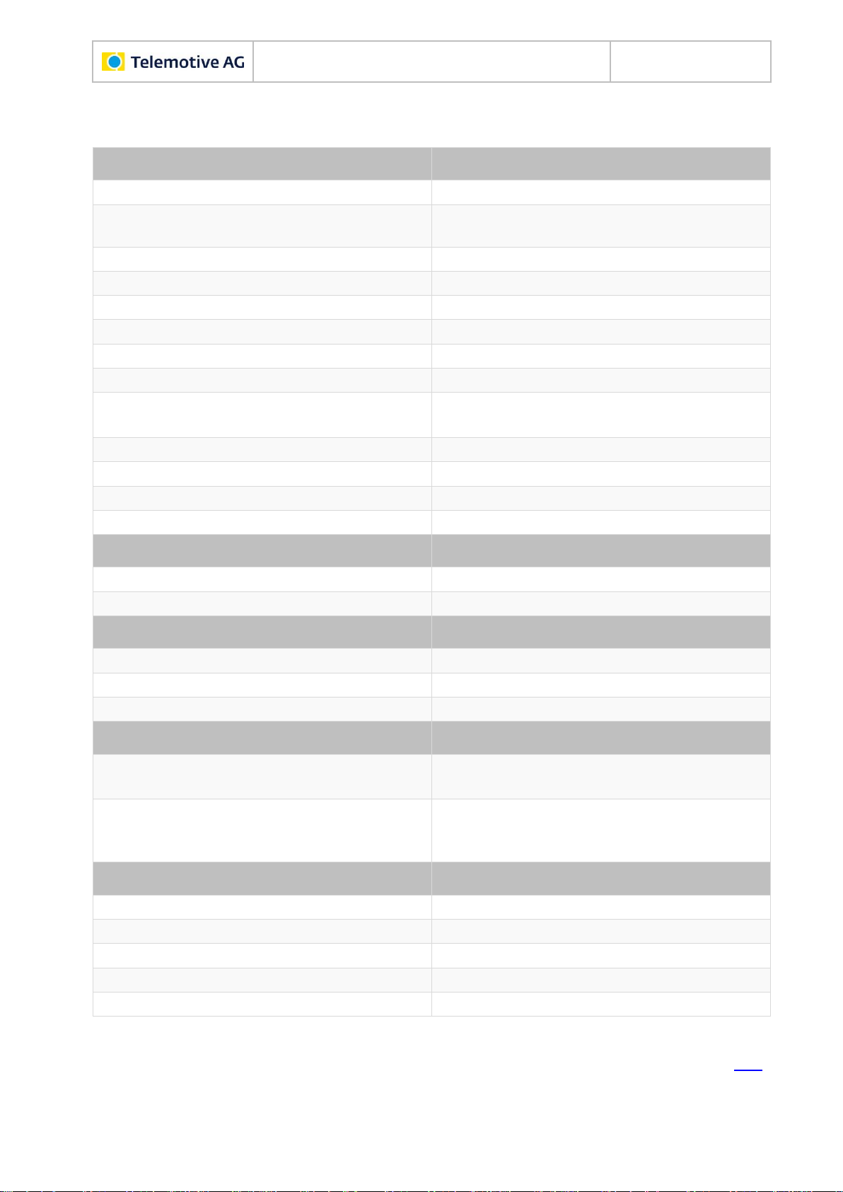
7.1.1 Top view
Speaker
Brightness sensor
Home button
Active LED
State LED
Microphone
Touchscreen
Figure 7.1: Top view with components
Index
Remote Control Touch
User Guide
Datum: 08.12.2015
Seite 13 von 61
RCTouch_UserGuide_V2.1.1.doc
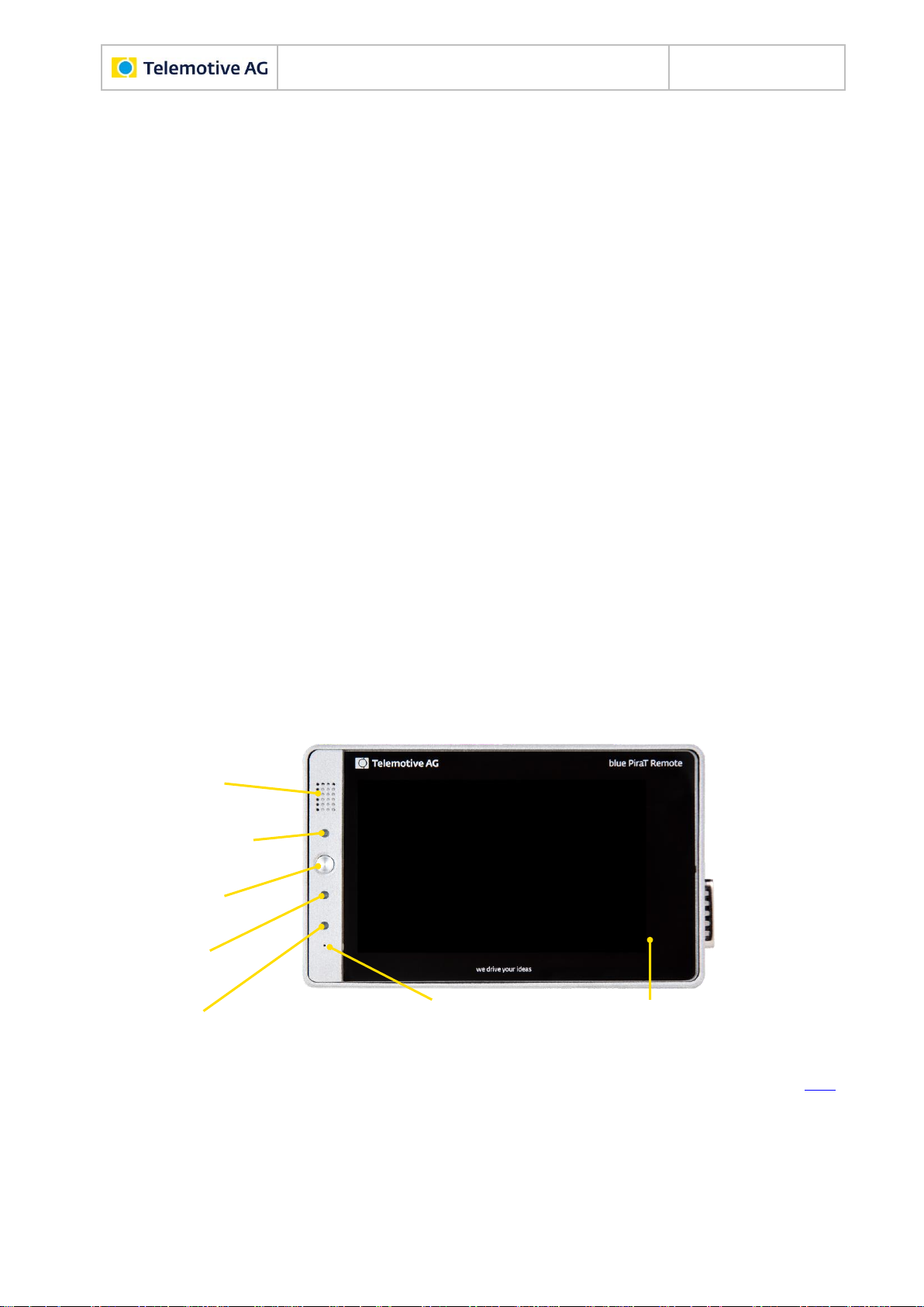
7.1.2 Side view, from the right
1
8-pol LEMO socket
2
Gbit Ethernet (RJ45)
3
Gbit Ethernet (RJ45)
Figure 7.2: Side view, from the right with components
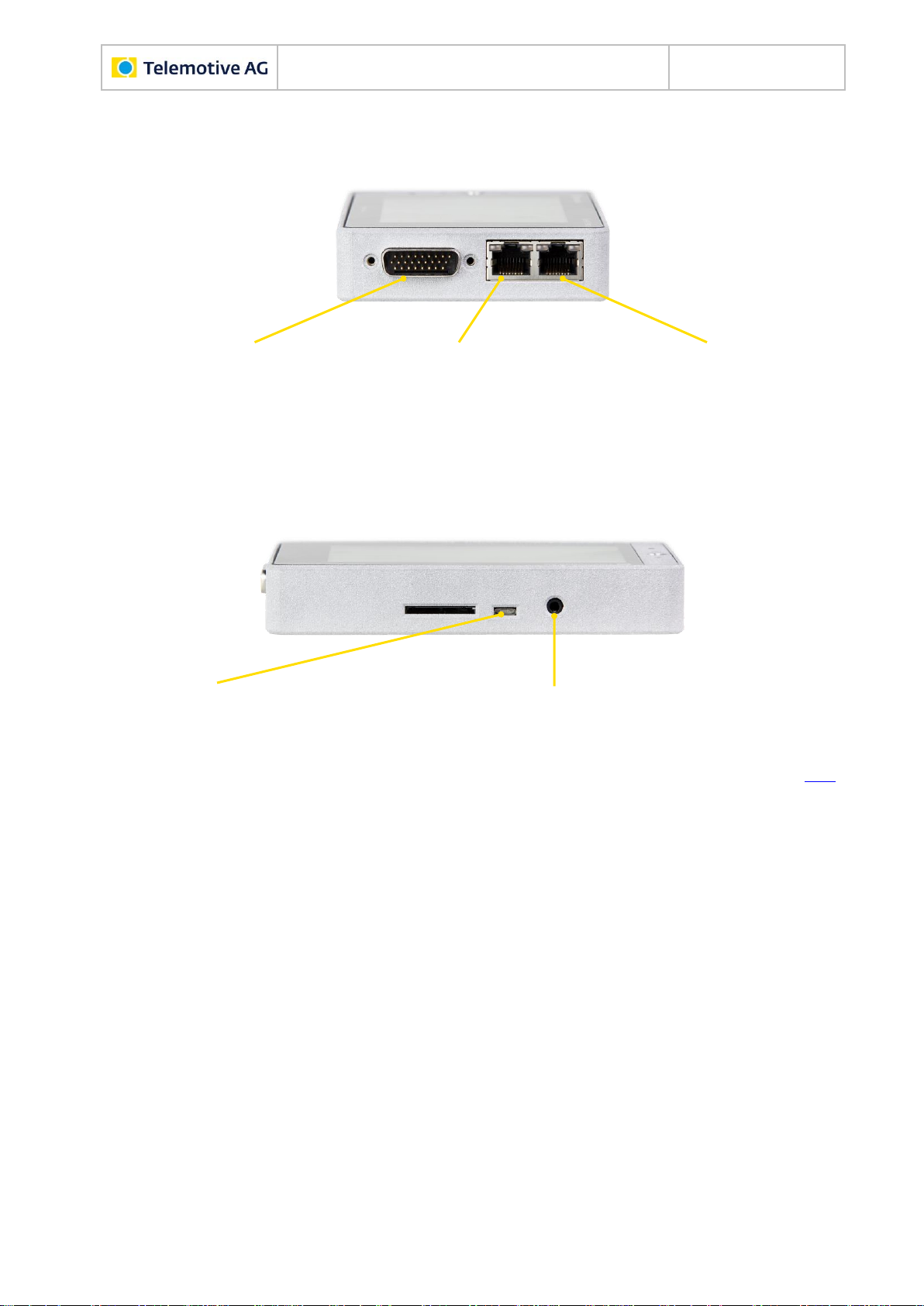
7.1.3 Rear side
4
Mini USB 2.0
5
4-pol audio jack plug stereo out/microphone (3.5 mm) OMTP
Figure 7.3: Rear side view with components
Index

Remote Control Touch
User Guide
Datum: 08.12.2015
Seite 14 von 61
RCTouch_UserGuide_V2.1.1.doc
7.2 Functionality of components
Functionality of the components is impaired by certain conditions such as moisture, darkness,
heat or cold, mechanical action, dirt or similar. Observe therefore the points described in chap-
ter 5 Maintenance provisions and safety regulations.
7.2.1 Ports
The ports are used to connect the RCTouch, for example with the power supply (see section
7.4.1).
Port
Cable
Connection with …
No.
Designation
1
8-pol LEMO socket
Power cable with Lemosa connector to
banana plug or
Power cable with Lemosa connector to
DIN plug
Power source
2
Gbit Ethernet (RJ45)
Gbit Ethernet cable
Client computer or
data logger
3
4
Mini USB 2.0
Micro USB connecting cable
USB devices
5
4-pol audio jack plug
stereo out/microphone
(3.5 mm) OMTP
3.5" jack/audio cable
Microphone, speak-
er, headset, etc.
Table 7.1: Available connections
7.2.2 Brightness sensor
The brightness sensor helps adjust the display's backlight depending on the ambient light. It
serves only the automatic regulation and is permanently active.
7.2.3 Home button
The Home button is used to switch the device on or off. It can also be used to switch between
applications and to wake up the device from sleep mode.
7.2.4 Speaker
The speaker is used to play voice notes. Its volume is adjustable.
Index

Remote Control Touch
User Guide
Datum: 08.12.2015
Seite 15 von 61
RCTouch_UserGuide_V2.1.1.doc
7.2.5 LEDs
Activity and operating state of the RCTouch are indicated by the LEDs.
Table 7.2: LED behavior
7.2.6 Microphone
The microphone is used to record voice notes on triggers. The voice recording is audible up to a
vehicle speed of 130 km/h.
7.2.7 Touchscreen
The display is used to operate the RCTouch. Only use the tip of the finger to operate it. The
brightness is adjustable.
7.3 Accessories
The RCTouch is supplied with a 2 m Ethernet cable.
Additional accessories are available for purchase. The following accessories are compatible
with the RCTouch:
mounting bracket
various adapter cables, including power cables
Please contact our sales department for more information about the accessories.
The relevant manuals for these enhancements can be found in the Telemotive ServiceCenter.
Index
Activity/operating state
Behavior
Active LED
State LED
device goes to standby
green pulsing
not lighted
in error mode
green light
red light
in operation
green light
not lighted
powered off
not lighted
not lighted
press Home button
brief light-up
not lighted
record voice note
brief light-up
red pulsing, four times
then not lighted
set trigger
brief light-up
not lighted
switch off device
green pulsing
not lighted
switch on device
green flashing
not lighted
update firmware
green light
red light
wake up device
brief light-up
brief light-up

Remote Control Touch
User Guide
Datum: 08.12.2015
Seite 16 von 61
RCTouch_UserGuide_V2.1.1.doc
7.4 Installation
The RCTouch requires a connection to the power supply and one to the client. Then the
RCTouch can be used in standalone mode.
In order to make full use of all functions of the RCTouch, a connection to at least one blue PiraT
data logger is required. This creates a Telemotive System Link (TSL).
Find more information about client and TSL in the Telemotive System Client user guide.
7.4.1 Cable connection
Note:
Connect the RCTouch only with devices of Telemotive AG (blue PiraT, Remote Control).
7.4.1.1 With power supply
Note:
Make sure that the RCTouch is switched off before connecting it with a power supply or
disconnecting it.
The power connection of the RCTouch is similar to that of the Remote Control Voice.
They are NOT identical. We therefore recommend to use the device-specific cable.
The power supply can be established using the blue PiraT data logger's universal cable set or
by connecting directly to the power source.
7.4.1.1.1 Direct connection
A power cable with Lemosa connector to banana plug is required for the direct connection of the
RCTouch to the power supply.
Figure 7.4: Power cable with Lemosa connector to banana plug
Index

Remote Control Touch
User Guide
Datum: 08.12.2015
Seite 17 von 61
RCTouch_UserGuide_V2.1.1.doc
7.4.1.1.2 Indirect connection via data logger
A power cable with Lemosa connector to DIN plug is required for the connection to the cable set
of a blue PiraT data logger.
Figure 7.5: Power cable with Lemosa connector to DIN plug
Plug the Lemosa connector into the RCTouch and the banana plug into the power supply
(red/Vbat /+/Terminal 30 and black/GND/-/Terminal 31) respectively the DIN plug into the
cable set of the blue PiraT.
7.4.1.2 In the network
The RCTouch has two Ethernet ports. The loggers to be controlled are connected directly via
Ethernet to the RCTouch. These loggers must establish a TSL network with the RCTouch in
order for the RCTouch to recognize them. The client computer can be connected to a free
Ethernet port of the TSL chain.
Figure 7.6: Example TSL network with one bPMini, one RCTouch and one bP2
Index
7.4.2 Client
Note: When delivered, the RCTouch is configured as a DHCP server.
Open your internet browser.
Enter the IP address of the RCTouch in the address bar. (IP factory setting: 192.168.0.233)
Press the [Enter] key.
The computer connects to the data logger.
The TSL Client Portal opens.

Remote Control Touch
User Guide
Datum: 08.12.2015
Seite 18 von 61
RCTouch_UserGuide_V2.1.1.doc
Figure 7.7: TSL Client Portal
Note:
Your network connection must be set to “Obtain IP address automatically”.
Click [Download], to download the Telemotive System Client directly from the logger.
Follow these steps, depending on your browser:
Browser
Proceeding
Internet Explorer
Click [Save], to locally save the file on your system.
Click [Accomplish].
Mozilla Firefox
Click [Save file], to locally save the file on your system.
Click the arrow on the right top of the browser menu and select the down-
loaded application in the appearing context menu.
In the dialog that opens select the desired software language from the dropdown menu.
Click [OK].
Follow the instructions in the next dialog and select an installation directory.
Click [Install].
Client is installed.
Shortcut to “Telemotive System Client” appears on the desktop and in the start
menu.
Figure 7.8: Shortcut to client
Index

Remote Control Touch
User Guide
Datum: 08.12.2015
Seite 19 von 61
RCTouch_UserGuide_V2.1.1.doc
8 Surface
This chapter describes the application setup and the layout of the individual views as well as the
displays contained.
The RCTouch software is very user-friendly thanks to its graphic surface and the clear outline.
Figure 8.1 shows the outline of the application in <Home> view and four applications. The appli-
cation views contain minimum one tab. For the applications Driver View and Settings, the num-
ber and naming of the tabs is set.
Figure 8.1: Application sitemap
Note: “n” stands for any number of devices
When an application is launched for the first time after switching on, the uppermost tab is
shown. The next time you launch the application, the tab last opened is shown, except for the
application Busload.
Index
8.1 Layout of the views
All views consist of a window and a dark blue frame.
Home
Status
Driver View
Busload
Settings
Overview
*Name RCTouch*
*Device name 1*
Functionkeys
Markerlist
Analog
Camera
CAN
CCP_XCP
GPS
*Device name 2*
*Device name n*
…
General
USB
Serial
MOST150
LIN
Ethernet
Digital
Remote Control Touch
User Guide
Datum: 08.12.2015
Seite 20 von 61
RCTouch_UserGuide_V2.1.1.doc
As the window contents vary depending on the view, they are described in more detail in the
following sections of this chapter.
The dark blue frame contains in all views a header bar on top and, with the exception of the
<Home> view, a tab bar at the bottom.
Header bar
Window
Tab bar
Figure 8.2: Components of the application views
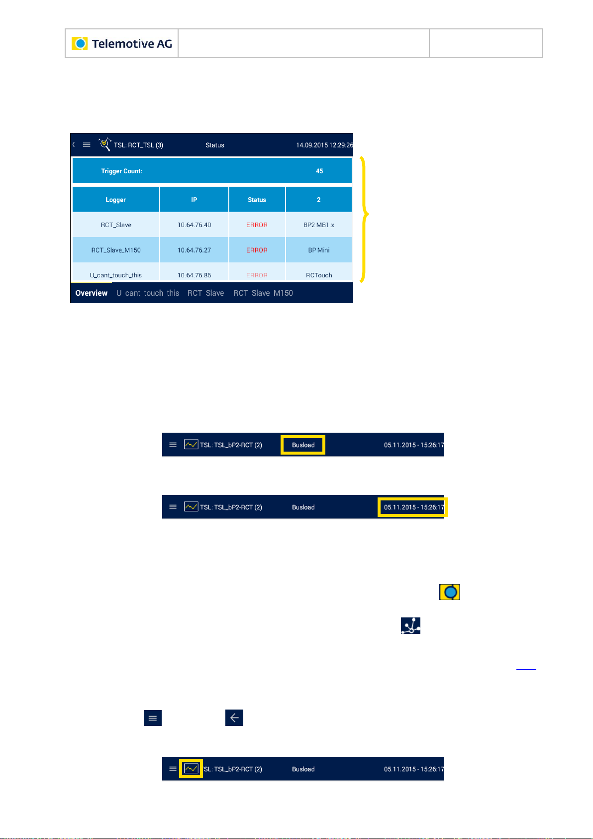
8.1.1 Header bar
In each view the header bar contains:
the designation of the current view and
date and time of the device or the TSL network.
Depending on the operating mode, two representations are possible in the top left corner of the
<Home> view:
1. If you operate the device in standalone mode, the Telemotive logo and the device
name are shown.
2. If you operate the device in the TSL network, the TSL logo and the TSL name are
shown.
Index
In the application views, the header bar contains on the left:
the key respectively for the side menu,
the icon of the current application (see section 8.2) and
Other manuals for blue PiraT2
2
This manual suits for next models
1
Table of contents
Other Telemotive AG Data Logger manuals


