Telesis FQ20 User manual
FQ20 Laser Marking System
System Overview
The Telesis®FQ20 is one laser in a family of maintenance-free,
Q-switched, Ytterbium fiber lasers designed for marking
applications. These lasers deliver a high power laser beam directly
to the marking surface via a flexible, metal-sheathed fiber cable.
The fiber based optical design and rugged mechanical design
allows the Telesis FQ20 to operate in an industrial environment
where shock, vibration, and dust are a concern.
The FQ20 unique design allows for a remote beam delivery
system. The galvanometer package is attached to a fiber-optic
delivery system from a remote laser engine. This allows the
overall package to be very small and modular.
The FQ20 fiber laser offers these advantages:
•Standard 115/230 VAC operation
•Over 50,000 hours of reliable, maintenance-free performance
•Compact size and modular construction
•Output laser beam delivery via a fiber optic cable
•Exceptional beam quality and stable output power
•Active AO Q-switching
•Display for monitoring actual laser power
•Display for monitoring hours of operation
•Sealed head to prevent dust contamination in optical chamber
•Visible red diode for aiming and dry run operations
•Air cooled
•DoD-compliant Unique Identification (UID) marking
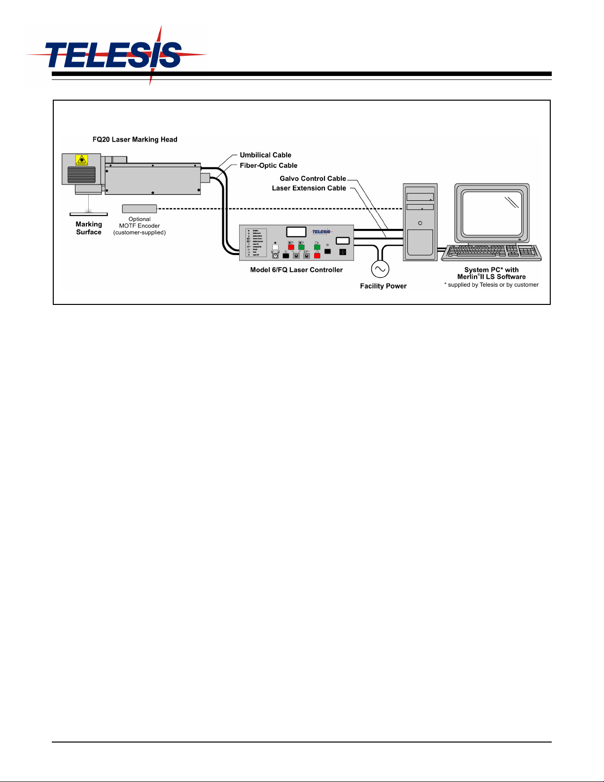
System Configuration
The FQ20 is available in two configurations. One is capable of
marking only stationary objects. The other is capable of marking
objects while they are moving (i.e., mark-on-the-fly operation).
The basic lasersystem consists of the following components.
•Laser Controller – contains the laser source unit, circuit
boards, electrical components, and the operator console
•Fiber Optic Cable Assembly – with optical isolator
•Laser Marking Head – includes the shutter assembly,
visible red aiming diode, galvanometer assembly, and flat-
field lens
•Software – Merlin®II LS Laser Marking Software
•System Computer – supplied by Telesis or by customer
The modular design allows for major components to be easily
replaced and returned to Telesis if required.
Laser System Options
•Desktop computer or Notebook computer with powered
cardbus-to-PCI expansion enclosure
•Externally-mounted focus-finder diode
•Mark-on-the-fly kit to interface with customer-supplied
encoder for marking objects in linear or circular motion
•Tool post w/ manual hand crank for z-axis adjustment
•Pushbutton station (start/abort)
•I/O Options:
TTL via PCI-DIO24 Card (Kit #53920)
Opto-isolated via Merlin DCIO Module (Kit #53928)
Two-axis Controller (for auxiliary axes; additional I/O)
•Programmable X-, Y, or Z-axis (requires two-axis controller)
•Rotary drive fixture (requires two-axis controller)
•Vacuum System
•Workstation / Work area enclosures
•Remote operation via optional pendant
Doc No. 47773 Rev. E © 2007 – 2009 Telesis Technologies, Inc. – All Rights Reserved 1 of 7
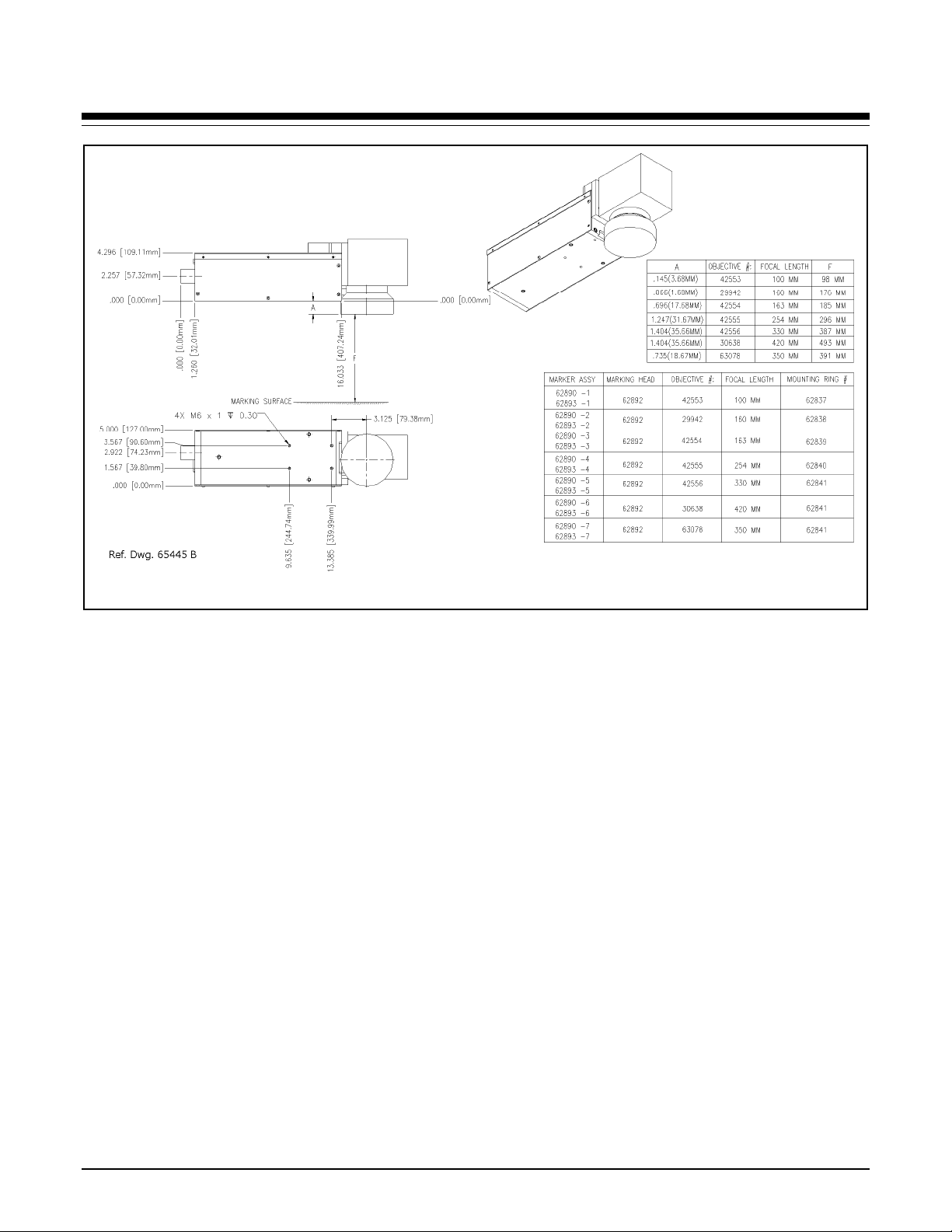
FQ20 Laser Marking System
FQ20 Laser Marking Head Dimensions and Mounting Details
System Setup
Complete installation procedures are provided in the FQ20
Installation/Maintenance Manual. The following procedures are
listed for reference only to provide a general overview of the
installation process.
Note: A minimum distance of 8 in. (204 mm) should be allowed
at the rear of the laser controller to allow for a proper bend radius
of the fiber optic cable. A minimum of 4 in. (102 mm) should be
allowed on each side of the controller to permit proper air flow.
Do not block the vented openings on the laser controller.
Note: A minimum distance of 8 in. (204 mm) should be allowed
around the laser marking head. This permits proper air circulation
and allows room for a proper bend radius of the fiber optic cable.
1. Equipment should remain powered down and in the OFF
position until the mounting is complete.
2. Place the computer, monitor keyboard in the desired location.
3. Place the controller as close as practical to the laser marking
head. The standard cable length is 5 meters (16 feet).
4. Place the laser marking head onto the mounting position
taking care not to bend or kink the fiber optic cable. The
fiber optic cable will take an approximately 12 in. (305 mm)
diameter bend without damage.
5. Mount the laser marking head by using four M6-1.0 bolts.
Torque to 80 in-lb (9.04 N-m).
a. Mounting holes are tapped for metric threads. The
mounting pattern is a four (4) hole rectangular pattern
2.0 in. wide by 3.75 in. long (50.8 x 95.25 mm). The
holes are tapped 0.30 in. (7.62 mm) deep for M6-1.00
bolts. Mounting bolts must not extend into the
laser marking head as to interfere with the
internal components.
b. The leading edge of the mounting plate must not
extend more than .375 in. (9.5 mm) forward of the
first set of holes to allow clearance for the beam
output lens.
c. As viewed from the back of the laser marking head,
the center of the output beam is 3.125 in. (79.375mm)
forward of the first set of mounting holes and
0.732 in. (18.593 mm) inward from the left side set of
mounting holes.
6. Ensure laser controller power switch (on front panel) is OFF.
7. Select proper fuse arrangement, then connect power cable.
8. Connect the remaining cables.
9. Refer to the FQ20 Operation Supplement for proper startup
procedure of the complete system.
10. Refer to the Merlin II LS Operating Instructions for
complete information on using the system software.
Doc No. 47773 Rev. E 2 of 7
FQ20 Laser Marking System
Doc No. 47773 Rev. E 3 of 7
System Specifications
Compliance............................ CDRH, CSA
Laser Type............................. Q-switched Ytterbium fiber
Wavelength............................ 1060 nanometers (±10 nm)
CW Average Power .............. 20 watts
Expected Diode Lifetime....... >50,000 hours
Long Term Output
Power Drift......................... ± 5%
The laser marking head produces a visible red diode that may be
viewed on the work surface without the need for protective safety
goggles. This provides a safe and convenient aid for laser setup
and part programming. Since the red beam is located after the
shutter, the aiming beam may be used with the shutter opened or
closed. Additionally, the visible red beam may be used with the
lasing beam
Avg. Power Consumption...... < 500 watts
Input Power ........................... 95 to 250 VAC 50/60 Hz
Supply Voltage Fluctuation ... ± 10%, maximum; clean ground line
Oper. Temperature................. 18° to 35°C (65° to 95°F)
Recommended Temp............. 20° to 25°C (68° to 77°F)
Oper. Relative Humidity........ 10% to 85%, non-condensing
Laser Marking Head
The laser marking head includes the shutter assembly, visible red
aiming diode, circuit board, galvanometer assembly, and the flat-
field lens. The beam collimator and isolator (at the end of the fiber
optic cable) are enclosed within the laser marking head.
Laser Marking Head Specifications
Dimensions (L x W).............. 510.464 x 127.000 mm
(20.097 x 5.000 in.)
Dimensions (H)...................... Dependent on lens selection:
100mm: 144.120 mm (5.674 in.)
160mm: 142.113 mm (5.595 in.)
163mm: 158.115 mm (6.225 in.)
254mm: 172.110 mm (6.776 in.)
330mm: 177.622 mm (6.993 in.)
350mm: 159.106 mm (6.264 in.)
420mm: 177.622 mm (6.993 in.)
Mounting Weight.................. approx. 6.82 Kg (15 lbs.)
Mounting Holes..................... four factory-tapped M6-1.00
Aiming................................... visible red diode beam
Field Resolution..................... 16 bit (65535 data points)
Galvanometer Repeatability .. less than 22 micro radian
Marking Field Size ............... lens-dependent, see chart
Fiber-Optic Cable Length...... 3 m (9.8 ft.)
Umbilical Cable Length......... 5 m (16.4 ft.), detachable
Laser Ext. Cable Length........ 3.05 m (10.0 ft.), detachable
Marking Field Size
The size of the marking field is dependent on lens type.
See Flat-Field Lens.
Visible Red Aiming Diode
during the marking cycle. Note that protective
eyewear must always be worn when the laser is in operation.
Flat-Field Lens
The flat-field lens is key to the marking performance of the
system. This is the final coated optical lens that the beam will pass
through before it strikes the marking target. This lens is called a
flat field lens because when the beam is focused, the focus lies in a
plane perpendicular to the optical axis of the lens. To protect the
lens from dust and debris, a clear protective cover is inserted
between the work area and the lens.
The following chart outlines the available lenses, the resulting
image field provided by the lens, and the working clearance (in
millimeters and inches).
Lens
Image Field
(mm) (in.)
Working
Clearance
(mm) (in.)
100 mm 65 x 65 2.56 x 2.56 98 3.86
160 mm 90 x 90 3.54 x 3.54 176 6.93
163 mm 110 x 110 4.33 x 4.33 185 7.28
254 mm 175 x 175 6.89 x 6.89 296 11.65
330 mm 230 x 230 9.06 x 9.06 387 15.24
350 mm 250 x 250 9.84 x 9.84 391 15.39
420 mm 290 x 290 11.42 x 11.42 493 19.41
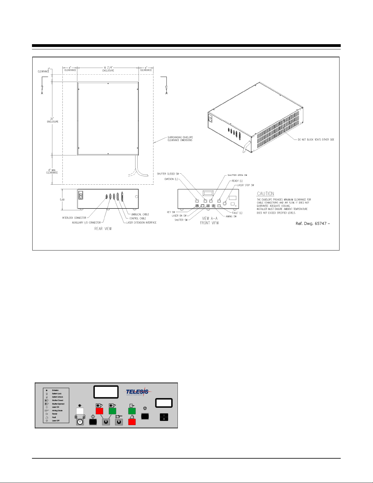
FQ20 Laser Marking System
Model 6/FQ Laser Controller Dimensions and Mounting Details
Laser Controller
The laser controller houses the laser source unit, power supplies,
circuit boards, programmable logic controller, control relay,
cooling fan, a 115/230VAC IEC320 connector, and a front panel
control module.
The laser source unit generates the lasing beam. Engineered for
the greatest reliability and for ease of maintenance, the laser
source is an easily replaceable sealed module with expected
lifetime of greater than 50,000 operating hours.
Operator Control Panel
The front panel control module includes the system key switch,
laser off push button, manual safety shutter control, function
indicators, an LCD panel to monitor elapsed emission time, and an
LED panel to monitor laser power.
Model 6/FQ Laser Controller
Laser Controller Specifications
Dimensions (W x H x D).......425.5 x 144.3 x 508.0 mm
16.75 x 5.68 x 20.00 in.
Surrounding Envelope...........628.7 x 152.5 x 762.0 mm
24.75 x 6.00 x 30.00 in.
Weight...................................approx. 15 Kg (33 lbs.)
Cooling..................................air cooled, fan
Fiber Optic Cable Assembly
The lasing beam is delivered to the laser marking head from the
laser controller through a fiber optic cable. One end of the fiber
optic cable is permanently attached to the laser source unit inside
the laser controller. The opposite end of the cable includes a beam
collimator and isolator that is enclosed within the laser marking
head. The standard fiber optic cable for the FQ20 is 3 m (9.8 ft.)
long.
Optical Isolator
To prevent back reflections an optical isolator is used in all
standard FQ20 Laser Marking Systems. Installed on the laser
marking head end of the fiber optic cable, the isolator functions as
a one way check valve allowing laser light to exit the laser but not
return to the laser’s most sensitive optical components.
Doc No. 47773 Rev. E 4 of 7
FQ20 Laser Marking System
System PC
The laser system requires an IBM-compatible computer for
running the MerlinII LS Laser Marking Software. The PC may be
a desktop or a notebook computer and may be supplied by Telesis
or by the customer. If the PC is supplied by Telesis, warranty for
the computer, computer keyboard, monitor, and peripherals
default to the original equipment manufacturer.
Galvo control cards are included, along with interconnect cabling.
The laser software is installed and the entire unit is tested as a
laser marking system.
The minimum computer requirements are as follows:
•Windows®2000, Windows®XP or Windows®Vista™ Business
•Telesis Merlin II LS Laser Marking Software
•Pentium®III with recommended RAM as per operating system
•Multi-gigabyte, HDD
•CD-ROM and 3.5 in. External Disk Drives
•SVGA Color Monitor, Mouse, and Keyboard
•Laser/Galvo Controller Board
(configured for stationary marking or marking “on-the-fly”)
•Video Card
•One available RS-232 Serial Port
•Two available USB Ports
•Three (minimum) full-height PCI Slots *
Note: If a notebook computer is used, expansion
must be used to provide the PCI slots.
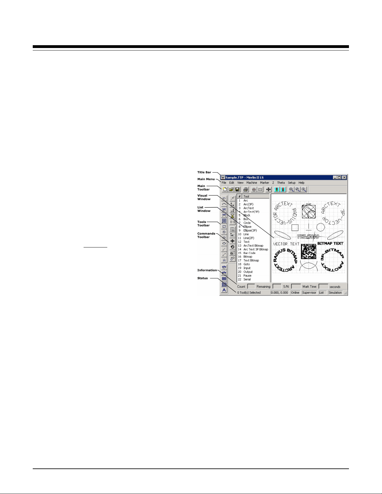
System Software
The powerful Telesis Merlin II LS Laser Marking Software is a
Windows®based operating software package that comes standard
with the laser marking system. It is a graphical user interface that
makes marking pattern design quick and easy. The WYSIWYG
(what-you-see-is-what-you-get) interface provides a to-scale
image of the pattern as it is created. Just “click and drag” for
immediate adjustment to field size, location, or orientation.
The MerlinII LS includes tools to create and edit text (at any
angle), arc text, rectangles, circles, ellipses, and lines. Multiple
fields may be grouped and saved as a block to form a logo.
Existing DXF files can also be imported for marking. Non-
printable fields can be created to clearly display a graphical
representation of the part being marked.
Overview of Merlin II LS User Interface
MerlinII LS Laser Marking Software Specifications
Operating System..................Windows®2000, Windows®XP, or
Windows®Vista™ Business using a
Desktop PC or Notebook PC
Font Generation.....................True Type Fonts
Barcodes and Matrix .............2D Data Matrix, PDF417, BC 39,
Interleaved 2 of 5, UPCA/UPCE BC
128, Maxi Code, Code 93, QR Code
and others
Graphic Formats....................Raster and Vector: BMP, GIF, JPG,
WMF, EMF, CUR, ICO, DXF
Serialization...........................Automatic and Manual Input
Host Interface Capable
Linear Marking......................Scalable with Letter Spacing
Control
Arc Text Marking..................Scalable and Adjustable
Drawing Tools.......................Line, Rectangle, Circle, Ellipse
Doc No. 47773 Rev. E 5 of 7

FQ20 Laser Marking System
Doc No. 47773 Rev. E 6 of 7
Remote Communications
The communication capability of the marking system software
allows you to control the laser from remote I/O devices. Remote
communications can be performed by connecting to a Host
computer, an optional I/O card, or an optional two-axis Auxiliary
Controller.
The rear panel of the controller also provides a connector to
monitor output signals that report the status of the shutter, laser
emission, and fault conditions.
Host Communications. Remote communications may be
executed from a host computer using RS-232 or Ethernet
(TCP/IP) connections to the system computer (i.e., the PC
running the Telesis laser marking software). The software
provides parameters to define the data transmitted to and from
the host. For more information on using and configuring these
parameters, refer to the Operation Manual supplied with the
laser marking software.
I/O Card. Telesis offers an optional I/O card that provides six
input signals (Start Print, Abort, and four programmable inputs)
and six output signals (Ready, Done, Paused, and three
programmable outputs). The I/O card is available in the
following kits. For more information on using the optional I/O
card, refer to the Telesis Optional I/O Card Installation
Supplement supplied in each of these kits.
Kit #53920 This kit is available for all Telesis laser systems.
It includes the I/O Card, SIPs resistor packs (pre-installed),
the software driver CD, and installation documentation.
This kit does not provide opto-isolated signals. If this kit is
used, it is the responsibility of the installer/integrator to
provide opto-isolation between remote I/O devices and the
I/O card. Refer to the OEM User’s Guide for signal
limitations.
Note: Telesis does not endorse direct connection of I/O
signals to the I/O card. Direct connections to high
current/high voltage devices will damage the card.
Kit #53928 This kit is available for all laser systems that use
the Merlin II LS Laser Marking Software. It includes Kit
#53920 (above), plus the Telesis I/O Interface Module and
two cable assemblies.
This kit provides opto-isolated signals between remote I/O
devices and the I/O card through the Telesis I/O Interface
Module. Additional opto-isolator board assemblies or
opto-isolated I/O rack assemblies are not required when
the interface module is used.
Two-axis Controller. Telesis offers an optional two-axis
controller for all laser systems that use the Merlin II LS Laser
Marking Software. The auxiliary controller provides an
interface for connecting six input and six output signals to and
from the laser marking system, and for connecting the optional
auxiliary axes: vertical (Z) axis, rotational (Theta) axis, and
linear (L1 and L2) axes.
Environmental considerations must be taken into account when
installing the auxiliary controller concerning contaminants and
EMI susceptibility. For details, refer to the Installation/
Maintenance Manual supplied with the controller.
Communications Protocol
Two types of host interface are supported (RS-232 or TCP/IP) and
two communication protocols are provided through the Merlin II
LS marking system software (Programmable and Extended).
Programmable Protocol. Programmable protocol provides one-
way (receive only) communication with no error checking or
acknowledgment of the transmitted data. You may use
Programmable protocol to extract a continuous portion of a
message string to print. This can be used with a host computer or a
bar code scanner. Note that XON/XOFF Protocol applies even
when Programmable Protocol is selected.
The Programmable Protocol Message Type identifies the type of
message sent from the host. It determines how the marker uses the
data it extracts from the host message string when Programmable
Protocol is used.
49 Message type 49 ("1") overwrites the content of the first
text-based field in the pattern with the data extracted from
the host message. Note that if the field contains message
flags, they will be overwritten, not updated.
65 Message type 65 ("A") updates the Offset Angle parameter
with the data extracted from the host message. Syntax for
the transmitted string is ±n where ± is a positive or
negative sign and n is an integer that represents the offset
angle for the marking window.
72 Message type 72 ("H") updates the Offset X/Y parameters
with the data extracted from the host message. Syntax for
the transmitted string is ±X.X,±Y.Y where ± is a positive
or negative sign, X.X represents the X-axis offset distance,
and Y.Y represents the Y-axis offset distance.
80 Message type 80 ("P") indicates the data extracted from the
host message is the name of the pattern to be loaded.
81 Message type 81 ("Q") updates the text in the first query
text buffer (buffer 0) with the data extracted from the host
message.
86 Message type 86 ("V") updates the text in the first variable
text field in the pattern with the data extracted from the
host message.
118 Message type 118 ("v") updates the first text field
encountered in the pattern that contains a variable text flag
that matches the specified string length.
If the host is providing the Message Type within the transmitted
text string, enter "0" in the Message Type parameter text box
displayed on the Programmable tab of the Host/Setup window.
0 Message type 0 (zero) indicates that the host will provide
the message type, field number (if applicable), and data (if
applicable). This option allows more flexibility by
delegating the message type selection to the host on a
message-by-message basis. It also allows you to direct data
to specific fields and/or query text buffers.
The host can use Message Type 0 to provide data to the
marking system. The marking system will insert data
transmitted with the message into the appropriate location.

FQ20 Laser Marking System
Doc No. 47773 Rev. E 7 of 7
Communications Protocol (continued)
Extended Protocol. Extended protocol provides two-way
communication with error checking. It is designed to provide
secure communications with an intelligent host device using pre-
defined message formats and response formats. It also provides
error checking using a block check code to detect faults in the
transmitted messages and to verify the data is properly received.
The Extended Protocol Message Type determines how the marker
uses the data it extracts from the host message string or from the
marking system software, as applicable.
1 Message Type "1" can provide data to a text string in the
pattern or poll the pattern for data.
A Message Type "A" can provide data to the system Offset
Angle parameter for the marking window or poll the
system for data.
E Message Type "E" allows the host to take the machine
offline. It also provides the option of displaying an error
message box with the provided data string.
V Message Type "V" can provide data to a variable text
string in the pattern or poll the pattern for data.
P Message Type "P" can load a pattern or poll the system for
the current pattern name.
O Message Type "O" places the marker online. This allows a
host computer to reset. For example, this may be used to
recover from a power outage when the marker is
unattended.
G Message Type "G" initiates a print cycle.
Q Message Type "Q" can provide data to the system query
text buffer or poll the system for data.
H Message Type "H" can provide data to the system X/Y
Offset parameters or poll the system for data.
S Message Type "S" is used to poll the system for the
machine status. The machine status is returned to the host
in an eight-character hexadecimal mask.
I Message Type "I" is used to poll the system for the I/O
status.
TRADEMARKS
Telesis and Merlin are registered trademarks of Telesis
Technologies, Inc. in the United States and/or other countries.
Pentium is a registered trademark of Intel Corporation in the
United States and other countries.
Vista is a trademark of Microsoft Corporation in the United States
and other countries.
Windows is a registered trademark of Microsoft Corporation in
the United States and other countries.
Other Telesis Industrial Equipment manuals


