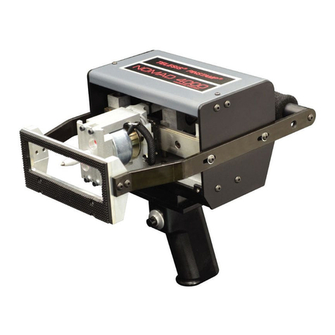
BenchMark®200/BM470 Marking System
34743A 7 of 8
BM470+ ENHANCED COMMUNICATIONS SOFTWARE
The optional BM470+ Enhanced Communications software allows
you to expand the controller’s communication capability. It makes
full use of the I/O Port available and allows you to configure the
Comm Port communication parameters. See I/O Control Signals and
Host Communications (below) for more information.
I/O Control Signals
Additional input and output signals are available through the I/O
Port only if the system uses the optional BM470+ Enhanced
Communications software. The I/O Port is configured for 12 to 24
VDC I/O only and may be used to connect a PLC or other DC I/O
source. The optically-isolated I/O Port allows you to remotely
select and load patterns, start printing, stop printing, place the
marker online, and monitor the system output signals. Cable
connectors and connector pins are supplied with the controller for
constructing appropriate interface cables.
Input Signals. These input signals provide the following controls:
INPUT COMM................... For all inputs (+ or – supply)
START PRINT .................. Begins print cycle
STOP ............................... Stops the print cycle
SEL_0 thru _6 *................. Remotely selects & loads up to
127* pattern files
SPARE_1, 2, 3.................. Three (3) spares for custom
applications
*System software allows SEL_6 signal to be configured for remotely
selecting patterns or for remotely placing the marker online. If used for
marker online, pattern selection is reduced to 63 patterns (max).
Output Signals. These output signals indicate the following
states:
OUTPUT COMM............... For all outputs (+ or – supply)
DONE ............................... Print cycle is complete
READY ............................. System ready for message or for start
print command
PAUSED .......................... System paused (waiting timeout or
command)
NO FAULT ....................... System status (normal or fault
detected)
SPARE_1, 2...................... Two (2) spares for custom
applications
Host Communications
The BM470+ Enhanced Communications software allows you to
configure the RS-232 parameters for the Comm Port.
The serial interface is most often used to connect a host computer,
a data terminal, or a bar code scanner. The following describes the
serial data character format for all transmissions to and from the
BM470 Controller.
•Asynchronous
•1200, 2400, 4800, 9600, 19200, 38400, or 115200 Baud
•1 or 2 Stop Bits
•7 or 8 Data Bits
•None, Even or Odd Parity
Host Communications (continued)
In addition defining Comm Port communication parameters, you
can select the type of protocol to be used: Extended Protocol or
Programmable Protocol.
Programmable Protocol. Use this protocol where very simple
one-way communications are required (such as with bar code
scanners). Programmable Protocol provides no error checking or
acknowledgment of the transmitted data. Note that XON/XOFF
Protocol applies even when Programmable Protocol is selected.
Starting Character specifies where the software begins to
count character positions. This number must be entered in
decimal format (e.g., “2” for ASCII Start of Text “STX”).
Terminating Character identifies the end of transmitted string
(usually “13” for ASCII carriage return character).
Character Position counted from the starting character
ignoring all characters preceding it.
Character Length accepts variable length messages (if set
to 0) or messages of a pre-specified, fixed number of characters.
Ignore Character identifies the character to ignore when sent
from the host (usually “10” for ASCII line feed character)).
Message Type allows message-type recognition which defines
how the marking system will use data it receives from the host.
1Message type 1 overwrites the first line of the first text
field with data extracted from the host
PMessage type P loads a specific pattern identified by
data extracted from host
QMessage type Q updates the text in the first query
buffer with data extracted from the host
VMessage type V updates the first variable text flag
found in the pattern with data extracted from the host
0Message type 0 (zero) indicates that host will provide
message type, field number (if applicable), line number
(if applicable), and data; delegates message type
selection to the host on message-by-message basis.
The host message must use the format:
Tnn<string>
where:
T = 1, P, Q, or V to indicate message type
nn = two-digit field number or query text buffer
where data will be placed.
Note: Not used with Message Type P.
<string> = For Message Type P, indicates the pattern
name to be loaded.
For Message Types 1, Q, or V, indicates
the data to be inserted into the field or the
query text buffer, as applicable.


