ABB Relion 630 Series User manual

—
RELION® 630 SERIES
Power Management
PML630/Compact Load-Shedding
Solution
Product Guide

Contents
1. Description..................................................................... 3
2. Power management systems......................................... 3
3. Load-shedding............................................................... 3
4. Application .................................................................... 3
5. Communication.............................................................. 4
6. Network architecture for cPMS load-shedding
Configuration A...............................................................5
7. Terminology....................................................................7
8. Power network configuration support in cPMS
load-shedding Configuration A....................................... 7
9. Configuration flexibility.................................................... 8
10. Network configuration for cPMS load-shedding
Configuration B............................................................. 8
11. Communication architecture support...........................10
12. System protection and control functions..................... 10
13. Load-shedding inputs and outputs..............................15
14. Disturbance recording ................................................ 18
15. Event log..................................................................... 19
16. Load-shedding performance....................................... 19
17. Redundancy................................................................20
18. Self-supervision...........................................................21
19. Access control............................................................ 21
20. Time synchronization...................................................21
21. Integration into switchgear...........................................21
22. Technical data.............................................................23
23. Front panel user interface............................................ 36
24. Mounting methods...................................................... 36
25. Selection and ordering data ........................................37
26. Accessories.................................................................40
27. Tools...........................................................................40
28. Supported ABB solutions ........................................... 42
29. Terminal diagrams.......................................................43
30. References..................................................................44
31. Functions, codes and symbols.................................... 45
32. Document revision history........................................... 47
Disclaimer
The information in this document is subject to change without notice and should not be construed as a commitment by ABB. ABB assumes no responsibility for any errors
that may appear in this document.
© Copyright 2019 ABB.
All rights reserved.
Trademarks
ABB and Relion are registered trademarks of the ABB Group. All other brand or product names mentioned in this document may be trademarks or registered trademarks
of their respective holders.
Power Management
1MRS757334 E
PML630/Compact Load-Shedding Solution
Product version: 1.2.1
2 ABB

1. Description
PML630 is a power management device that provides
comprehensive load-shedding solution for the power network
in an industrial plant. It protects the plant against blackouts and
power source outages due to system disturbances. PML630 is
a member of ABB’s Relion® product family and a part of its 630
series characterized by their functional scalability and flexible
configurability.
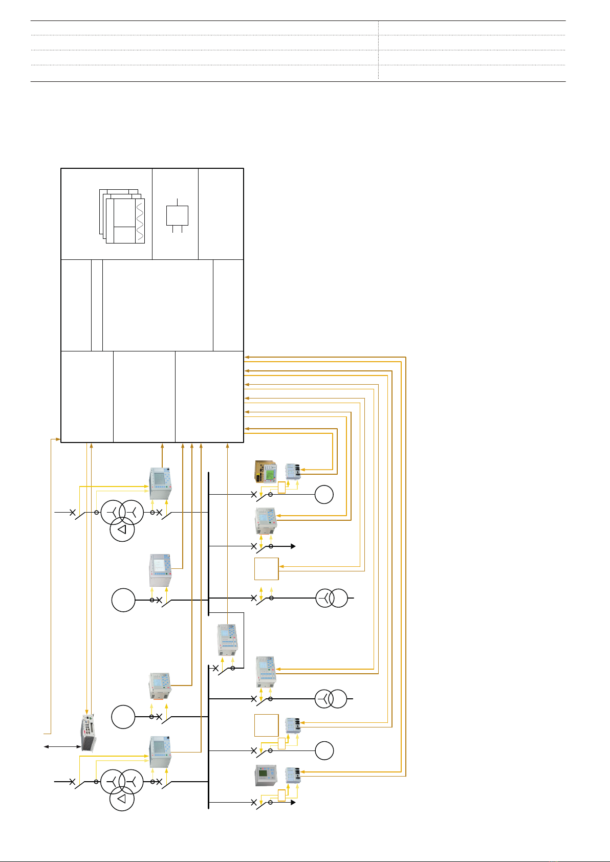
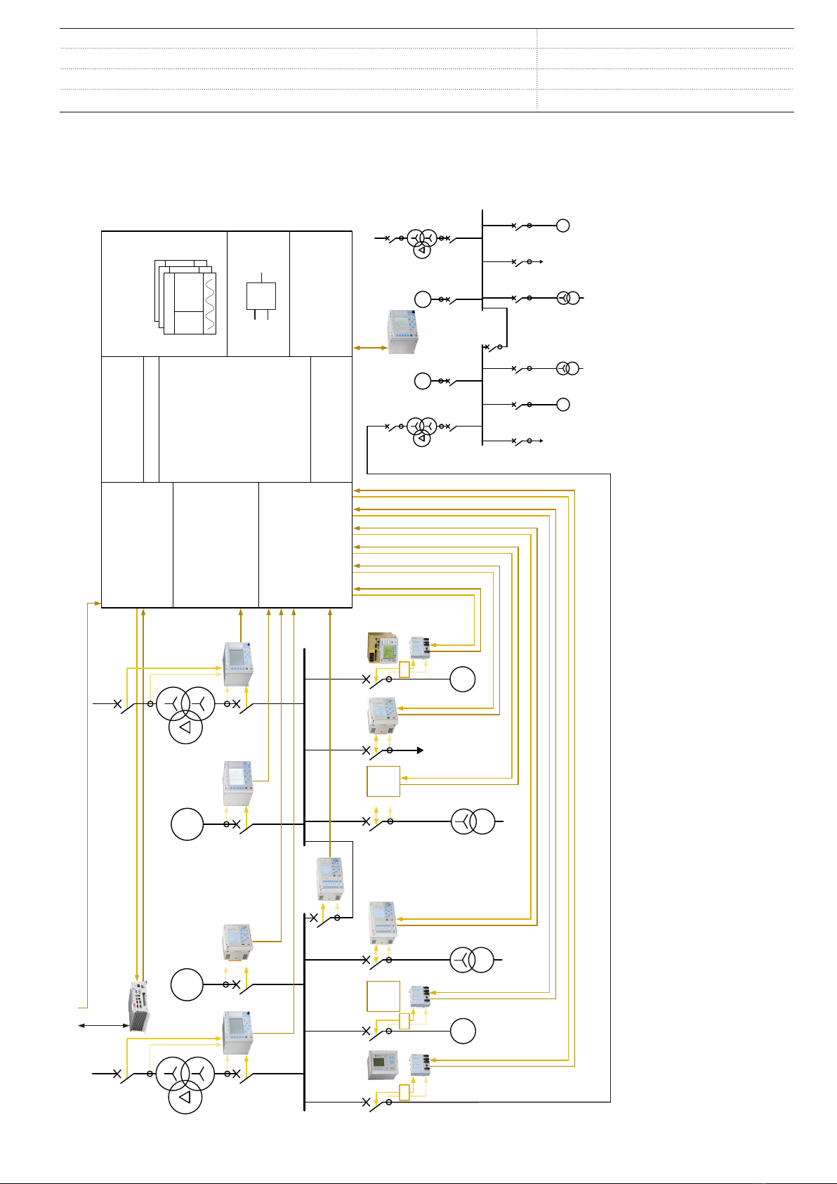
PML630 complies to IEC 61850 and offers seamless
connectivity with Relion 630, 620 and 615 series protection
relays, RIO600 IO units and COM600 to realize the load-
shedding functionality. The device uses GOOSE and MMS
communication profiles for I/O data exchange with other Relion
product family protection relays and COM600 series products.
2. Power management systems
Power Management Systems (PMS) is essential for a safe,
efficient and reliable operation of a power system within an
industrial complex. The PMS functionality suite includes load-
shedding, generator control, power sharing, network
synchronization and power restoration.
PMS solutions protect and optimize the stability of industrial
systems against disturbances by ensuring power sharing
between generators when the industrial power system is
islanded from the grid. These solutions also ensure that the
generators meet the required power demand when the network
is grid-connected. By ensuring fast acting load-shedding
action, generator tripping can be avoided and thereby
facilitating possible islanding of the network.
PMS solutions are suitable for industrial power networks.
• With captive power generation - islanded or grid-
connected
• With substantial and critical loads
• With unstable grid connectivity
• Without grid connectivity
The PMS functionality suite is applicable in various industrial
segments. Some of the industrial segments are Oil and Gas,
Marine, Pulp and Paper, Metals, Minerals, Building automation,
Infrastructure, Food and Beverage. In power utilities, load-
shedding application is particularly relevant.
3. Load-shedding
Load-shedding is required when the electrical load demand
exceeds the capacity of available power sources subsequent to
the loss of power sources or network disintegration. The load-
shedding system has to ensure the availability of electrical
power to all essential and, most importantly, critical loads in the
plant. This is achieved by switching off the non-essential loads
in case of a lack of power in the electrical network or parts of the
electrical network (subnetwork or island).
The load-shedding functionality can also be deployed in
industrial power networks with sole dependency on the utility
networks.
The lack of electrical power can be caused by a loss of
generation capacity or power grid connectivity or the tie line
feeding power to the plant.
Based on the shortfall of available power in the power network,
the load-shedding action initiated by the system ensures that
only identified loads are shed, system is stable after load-
shedding and impact on the associated plant operation is
minimal. The system allows flexibility to select or deselect the
load feeders to be load-shed at any point in time during plant
operation.
Furthermore, the load-shedding function should not operate if
the situation in the power network does not necessitate such an
action. Thus, it has to be accurate and selective.
4. Application
PML630 provides system level protection to small or medium-
sized industrial systems from the system disturbances. The
device supports different modes of load-shedding functions.
• Fast load-shedding
• Slow (overload or maximum demand violation-based)
load-shedding
• Manual load-shedding
• Underfrequency load-shedding as a backup to fast and
slow load-shedding
A network power deficit occurs when a power source such as a
generator or a grid transformer trips. There could also be a
power shortage when a network becomes isolated due to trip of
a bus coupler or a bus tie breaker. The fast load-shedding
function protects the power network during a power deficit.
The fast load-shedding function takes corrective action before
the system frequency [1] drop and provides faster and accurate
load-shedding action based on the power balance calculations
and defined priorities. Thus, the function also contributes
towards faster improvement of the frequency profile of the
system.
The slow load-shedding function prevents the tripping of a
power source during an overload condition. The slow (overload)
load-shedding function triggers the load-shedding and resets
the overload condition by acting faster than the dedicated
overload protection function for the power sources. The
overload situation can arise due to the overcurrent detection in
a generator or grid transformer, or maximum demand violation
at the power grid incomer for a specified period of time. Based
on the amount of the overload, the slow load-shedding function
determines the required load to be shed and uses the power
[1] A frequency-based load-shedding scheme, at the feeder level, acts based on the frequency drop caused by a power deficit. It triggers the shedding of loads based on the preset rate of
change of the frequency or the discreet frequency value settings in their respective devices. It can sometimes result in excessive load-shedding.
Power Management
1MRS757334 E
PML630/Compact Load-Shedding Solution
Product version: 1.2.1 Issued: 2019-08-27
Revision: E
ABB 3

balance calculations for arriving at the load-shedding priority
and to initiate the load-shedding action.
Using the manual load-shedding function, the load-shedding of
multiple load feeders can be initiated based on priorities or the
required total power relief.
The underfrequency-based load-shedding function detects
frequency decay and activates the shedding mechanism
described for fast and manual load-shedding functions.
All load-shedding functions can be active concurrently.
5. Communication
PML630 only supports the IEC 61850 substation
communication standard and its GOOSE and MMS
communication profiles.
PML630 is optimized to interoperate with REF615, REG615,
REM615, RET615, REF620, REM620, RET620, REF630,
REG630, REM630, RET630, RIO600 and COM600S or
COM600F. All the load-shedding operational and control
information is exchanged over IEC 61850 GOOSE and MMS.
Other ABB IEC 61850 devices, such as Relion 670/650 series
intelligent electronic devices (IEDs) and AC800M, and HMI
systems like MicroSCADA, System 800xA, can also be
integrated into the solution cluster. However, PML630 can also
be made to interoperate with any non-ABB or third-party IEC
61850 devices, provided they are able to meet the functional
requirements for load-shedding.
Disturbance files in COMTRADE file format can also be
accessed using the IEC 61850 standard's MMS file transfer
services or any standard protocol like FTP. PML630 exchanges
analog and binary signal information with the mentioned
devices and IO units (horizontal communication) using the
GOOSE profile. It meets the GOOSE performance requirements
for tripping applications (Type 1A, performance class 1) like
load-shedding in distribution substations, as defined by the IEC
61850 standard. PML630 can also interoperate with other IEC
61850-compliant devices, tools and systems and
simultaneously report events to five different clients on the IEC
61850 station bus. It is connected to Ethernet-based
communication systems via the RJ-45 connector
(10/100BASE-TX) or the fibre-optic multimode LC connector
(100BASE-FX).
The GOOSE communication profile for load-shedding offers
several advantages.
• Minimal or no hardwiring between panels
– Substation LAN can be used as the transmission
medium of binary and analog process data between
devices.
– Less I/O hardware in devices
– Lesser maintenance costs (due to lesser wiring
diagrams, terminal blocks and connections)
– Better predictability in the system or functionality
verification
• Fast and reliable station bus for data transfer offered by
Ethernet LAN technology
• Fast performance enabled by GOOSE.
– No need for additional signal processing, for example,
intermediate interposing relays, filtering and flutter
suppressions in binary signal transfer.
– Much faster binary signal transfer between devices than
with conventional hardwiring
– High performance
• Supervision of signals being transferred over GOOSE for
data integrity (based on, for example, quality and
communication status)
Power Management
1MRS757334 E
PML630/Compact Load-Shedding Solution
Product version: 1.2.1
4 ABB

6. Network architecture for cPMS load-shedding
Configuration A
The integrated approach with PML630, 620, 630 or 615 series
feeder protection relays, RIO600 IO units and COM600S or
COM600F to realize load-shedding power management
solution is designated as cPMS (Compact Power Management
System) load-shedding Configuration A. The cPMS load-
shedding Configuration A is also a functionality feature in
PML630.
The load-shedding network architecture consists of devices,
their functional organization and inter-device communication.
PML630 performs load-shedding actions based on the binary
and measurement data it receives from the protection relays or
IO unit (RIO600) associated with generator feeders, grid
transformer feeders, motor or load feeders, bus coupler feeders
and bus tie feeders.
Using RIO600, non-IEC 61850 based feeders can be easily
adapted for the load-shedding functionality. All the binary IO
signals and the transducer inputs can be connected to RIO600.
Furthermore, the data exchange between PML630 and RIO600
is based on GOOSE like 630 and 615 series protection relays.
After making a decision to take load-shedding action, PML630
sends shedding commands to motor or load feeders through
their respective devices. The load-shed commands, when
issued through the Relion protection relays or RIO600, can
either be used to directly trip the circuit breaker or extended
using auxiliary relays.
COM600 series product monitors and controls the load-
shedding and substation operations. This is realized over the
IEC 61850 MMS communication between COM600S or
COM600F and PML630 and feeder protection relays. Since
RIO600 supports only GOOSE, it may be appropriate to have
the GOOSE communication association between RIO600 and
COM600S or COM600F.
The load-shedding functionality information can be exchanged
with any external system using the communication gateway
features of COM600S or COM600F. See the COM600S or
COM600F product documentation for more details.
Power Management
1MRS757334 E
PML630/Compact Load-Shedding Solution
Product version: 1.2.1
ABB 5

3rd party relay RET620 REF615 REF 542plus
M
M
GG
REF620
T+R T+R T+R
RET630 REG615 RET630
REF 543
COM600
REG630
3rd party relay
IEC 61850 communication
GOOSE profile
- for load-shedding functionality
processing input data and shed
commands
Web HMI
Local HMI
- load-shedding single line diagram
diagram with status indications and
measured values
- multipages
- 3x15 alarm multicolor indications
with programmable texts
- 5 freely programmable function
buttons
Supervision
- device self-supervision
Control functions
(cPMS configuration A)
- Fast load-shedding
- Slow load-shedding
- Manual load-shedding
- Underfrequency load-shedding
Disturbance records
- analog recording
- non-volatile
- post triggering of load-shedding
function
Disturbance records n
10:23:45
10:23:45
•
•
•
Disturbance records 2
10:23:45
10:23:45
•
•
•
Disturbance records 1
I1 =
I2 =
•
•
•
In =
10:23:45
10:23:45
•
•
•
Programmable logic
I/Os
- 14 BI / 9 BO
- 4 CT + 5 VT
- 8 CT + 2 VT
&
IEC 61850 communication
MMS profile
- for load-shedding display data and
function control
Engineering and configuration
- Optimized with Relion 630, 620
and 615 series, RIO600 and
COM600S/COM600F
Load-shedding data
Generator data
Load-shedding control
Load-shedding inputs
Load-shedding command
External systems
GUID-106F1EC8-32F1-4242-86B0-DF5381A15E30 V4 EN
Figure 1. cPMS load-shedding Configuration A functionality overview
Power Management
1MRS757334 E
PML630/Compact Load-Shedding Solution
Product version: 1.2.1
6 ABB

7. Terminology
The terminology in a cPMS load-shedding Configuration A
solution is described using an example of a simple power
network.
From Grid/external network
5 MW
(18)
5 MW
(10)
2 MW
(3)
2 MW
(2)
1 MW
(5)
0.5 MW
(1)
15 MW
7 MW
(9)
20 MW
10 MW
5 MW
(4) 3 MW
(5)
7 MW
(19)
- 5 MW
0 MW
From Grid/external network
1
2
1a
2a
3
4
5
7
8
9
10
6
GUID-DE901D73-586B-4BC2-9174-39DCB8DD32CB V2 EN
Figure 2. Terminology
1Power source - Generator
1a Generator Available Power (capacity)
2 Power source - Grid transformer
2a Grid Available Power (power limit)
3 Power busbars with power sources and loads
4 Load busbars with only load feeders
5 Network circuit breaker (critical circuit breaker)
6 Power source circuit breaker (critical circuit breaker)
7 Load-shedding feeder or load-shedding group
8 Load-shedding priority for load feeder
9 Power flow direction
10 Power network area (under PML630's load-shedding
responsibility)
8. Power network configuration support in cPMS load-
shedding Configuration A
PML630 can support power networks certain configurations.
• Six generators
• Two power grid utility connectivity (tie or transformer feeder)
• Six single busbars
• Four subnetworks with power sources
The grid feeder 1 can be connected to the power busbar 1 and
the grid feeder 2 can be connected to the power busbar 1 or 2.
GUID-96FDF815-0F08-432B- B 4 6 3 -A87421269BD9 V2 EN
Figure 3. Typical busbar configurations (not preconfigured)
PML630 can support a power network under certain
conditions.
• 23 critical circuit breakers consisting of eight power source
circuit breakers and 15 equivalent bus coupler/bus tie
network circuit breakers. For example, two circuit breakers at
either end of a bus tie feeder are considered as a single
equivalent bus tie feeder.
• 60 sheddable loads or load-shedding groups arranged
across six busbars (four power busbars and two load
busbars) with individual load-shedding priorities.
• 10 sheddable loads or load-shedding groups in a single
busbar.
• 19 user-assignable load priorities.
A load-shedding group can be considered if the number of load
feeders connected to a busbar exceeds 10. The maximum
recommended number of feeders under a load-shedding group
is three.
Power Management
1MRS757334 E
PML630/Compact Load-Shedding Solution
Product version: 1.2.1
ABB 7

9. Configuration flexibility
The configuration aspects provide flexibility in the allocation of
power sources (grid transformers and generators) depending
on the project requirements.
Connectivity from a power network to a utility grid or other
power networks can be achieved through the grid 1 or grid 2
power sources.
If the number of loads in a bus bar exceeds 10 and the number
of busbars is less than six, an additional busbar with a virtual
bus coupler (permanently closed status) can be configured. The
load feeders can be distributed across the two bus bars.
Additional binary and arithmetic logic can be realized for
tailoring the load-shedding functionality towards customer-
specific requirements.
10. Network configuration for cPMS load-shedding
Configuration B
When the power network configuration exceeds the limits
defined for PML630 in Configuration A, an additional PML630
device can be configured in a peer-to-peer fashion, thereby
dividing the network into sectors called power network areas.
Hence, each PML630 is responsible for the load-shedding
action in its respective area, based on the power source
capabilities and the inter-power network area connectivity
status. The coordination of the load-shedding actions between
the PML630 devices is achieved by suitable parametrization.
This arrangement of multiple PML630 devices in a peer-to-peer
fashion is designated as cPMS load-shedding Configuration B.
The PML630 devices communicate with each other over IEC
61850 GOOSE.
Likewise, the cPMS load-shedding Configuration B is also a
feature in PML630. The Configuration B is always built up over
and above the Configuration A and hence the latter is a
prerequisite.
The maximum recommended number of PML630 devices in the
peer-to-peer mode in a Configuration B is three.
The power network areas are connected to each other through
their grid 1 or grid 2 feeder connection points.
Power Management
1MRS757334 E
PML630/Compact Load-Shedding Solution
Product version: 1.2.1
8 ABB

3rd party relay RET620 REF615 REF 542plus
M
M
GG
M
M
G G
REF620
T+R T+R T+R
RET630 REG615 RET630
REF 543
COM600
REG630
PML630
3rd party relay
IEC 61850 communication
GOOSE profile
- for load-shedding functionality
processing input data and shed
commands
- data exchange with peer
PML630 devices
- for load-shedding data and control
information from external systems
Web HMI
Local HMI
- load-shedding single line diagram
diagram
- values, status indications
- alarms and events
- operational parameters
- 3x15 alarm multicolor indications
with programmable texts
- 5 freely programmable function
buttons
Supervision
- device self-supervision
Control functions
(cPMS configuration A)
- Fast load-shedding
- Slow load-shedding
- Manual load-shedding
- Underfrequency load-shedding
(cPMS configuration B)
- Extended load-shedding
Disturbance records
- analog recording
- non-volatile
- post triggering of load-shedding
function
Disturbance records n
10:23:45
10:23:45
•
•
•
Disturbance records 2
10:23:45
10:23:45
•
•
•
Disturbance records 1
I1 =
I2 =
•
•
•
In =
10:23:45
10:23:45
•
•
•
Programmable logic
I/Os
- 14 BI / 9 BO
- 4 CT + 5 VT
- 8 CT + 2 VT
&
IEC 61850 communication
MMS profile
- for load-shedding display data and
function control
Engineering and configuration
- Optimized with Relion 630, 620
and 615 series, RIO600 and
COM600S/COM600F
Load-shedding data
Generator data
Load-shedding control
Load-shedding inputs
Load-shedding command
External systems
GUID-D481C165-51D0-4DBE-8BEE-DC233C7A02FA V2 EN
Figure 4. cPMS load-shedding Configuration B functionality overview
Power Management
1MRS757334 E
PML630/Compact Load-Shedding Solution
Product version: 1.2.1
ABB 9

Handled by
PML630_1
Handled by
PML630_2
Handled by
PML630_3
GUID-22D27044-49A8-4DF4-9AAA-B541132106B2 V1 EN
Figure 5. Busbar arrangement
11. Communication architecture support
In a cPMS load-shedding configuration A with the maximum
number of feeders, PML630 can be simultaneously associated
with almost 100 devices (8 power source devices, 60 load
feeder devices, 30 tie feeder breaker devices, 1 COM600 series
product, 1 external controller such as AC800M) in cPMS load-
shedding configuration A and additionally 2 devices (peer
PML630 devices) in cPMS load-shedding configuration B. This
is based on the assumption of one device (630, 620 or 615
series or RIO600) per feeder and COM600 IEC 61850 proxy
server [1].
The feeder devices can further be classified into eight power
source devices, 15 or more equivalent network circuit breaker
[2] devices and at least 60 load feeder devices configured as
standalone loads or in load-shedding groups. For
configurations of about 40 devices, COM600S or COM600F
can be used for station automation and load-shedding HMI
functions. For configurations exceeding 40 devices,
MicroSCADA (SYS600) can be used for substation automation
HMI function and COM600S or COM600F for load-shedding
HMI function.
In such a situation, the COM600S or COM600F web page
displays can be configured to be accessed from the
MicroSCADA (SYS600) workplace. The COM600S or
COM600F displays for load-shedding are automatically
configured during the PML630 configuration process.
In case COM600S or COM600F is not opted as the HMI, then all
the load-shedding process displays need to be configured
manually in the MicroSCADA (SYS600) or 800xA (Aspect
Server) HMI nodes. Parameter setting for manual load-
shedding and reporting of binary information from RIO600 unit
requires IEC 61850 GOOSE handling in the HMI.
In a redundant configuration, two PML630 devices with
identical configurations can execute the load-shedding
functionality independently. All feeder devices are configured to
communicate simultaneously with both PML630 devices over
IEC 61850 GOOSE.
12. System protection and control functions
Network topology determination
In Configuration A, PML630 acquires the status of all the power
source and network circuit breakers in its own power network
area and determines the subnetwork arrangements (1...4).
Accordingly, the busbars are allocated to a particular
subnetwork.
[1] Used for manual load-shedding
[2] A tie feeder has two circuit breakers on either ends controlled by two protection relays
Power Management
1MRS757334 E
PML630/Compact Load-Shedding Solution
Product version: 1.2.1
10 ABB

If the busbar 3 is connected to the busbar 1, it is a part of the
subnetwork 1. Similarly, if the busbar 4 is connected to the
busbar 2, it is a part of the subnetwork 2. If all of them are
connected together, the busbars 2,3 and 4 belong to the
subnetwork 1. This information is displayed in the subnetwork
display page on COM600S or COM600F.
In Configuration B, when an adjacent area is connected through
the remote-end tie feeder circuit breaker to the power network
area under consideration, the information from the adjacent
area is considered for the load-shedding calculations by its
PML630 device. In case the tie feeder opens, the power
networks are automatically moved into the Configuration A
mode by their respective PML630 devices.
One subnetwork within a power network area (under one
PML630) can be in the Configuration B mode when it is
connected to the adjacent power network area (controller by
another PML630), while another isolated subnetwork can be in
the Configuration A mode.
Fast load-shedding for Configuration A
The fast load-shedding function protects the network during a
power deficit. A network power deficit occurs when a
generator, a grid transformer, a bus coupler or a bus tie feeder
circuit breaker trips. The fast load-shedding function can
monitor a maximum of four independent power networks.
During the power deficit in one of the networks, PML630
performs power balance calculations and arrives at a load-
shedding priority. It issues shedding commands to the loads
with priority less than or equal to the calculated priority.
In case of the cPMS load-shedding Configuration B, each
PML630 considers the spinning reserve information from the
adjacent power network area (sent by the peer PML630) and
considers the same available power values along with the
power sources from its own power network area for the overall
power balance calculations.
In Figure 6 configuration example, when AB, AC, BD and CD
connections are open, four subnetworks or power networks are
formed and when they are closed, a single subnetwork is
formed.
A B
AB
C D
CD
E F
EF
AC BD
CE DF
Subnetwork 1 Subnetwork 2
Subnetwork 3 Subnetwork 4
GUID-2DF91C16-08B5-4736-B8CF-EDB7D2924F83 V1 EN
Figure 6. Example of subnetwork formation in a power network area
for cPMS load-shedding Configuration A
In cPMS load-shedding Configuration A, the fast load-shedding
function monitors the available power from the power sources
based on their capability against the power consumption and
performs the power balance calculation for each subnetwork
using the following equation.
(
ΣPower available from generators including spinning reserve
+
ΣPower utility connection capacity
) ≥ (
ΣPower actual from
generators
+
ΣPower actual drawn from grid
) +
ΣPower of
inhibited
(
system or operator
)
or non-sheddable loads
)
For the power balance calculation in cPMS load-shedding
Configuration B, ensure conformity with the following equation.
(
ΣPower available from generators including spinning reserve
+
ΣPower spinning reserve from generators from connected
adjacent area
+
ΣPower utility connection capacity
) ≥ (
ΣPower
actual from generators
+
ΣPower actual drawn from grid
+
ΣPower of inhibited
(
system or operator
)
or non-sheddable
loads
)
If the above conditions are not met, load-shedding is initiated.
Power Management
1MRS757334 E
PML630/Compact Load-Shedding Solution
Product version: 1.2.1
ABB 11

ΣPower available from generators
=
ΣPower
actual generated
+
Σspinning reserve
ΣPower utility connection capacity
=
ΣPower
actually drawn from grid
+
Σadditional
drawing limit
(
based on contractual
conditions
)
•
ΣPspinning reserve
is the total reserve capacity
of all the generators in the subnetwork. This
depends on the ambient temperature and
the capability of a generator and its working
mode. The generator (governor) working
mode and capability information can be
either set as parameters or acquired from an
external device or system over IEC 61850
GOOSE [1].
•
ΣPactual from generators
and
ΣPdrawn from grid
equal the load consumption in the
subnetwork.
•
ΣPinhibited loads
is the total power
consumption of the load feeders that do not
participate in the load-shedding due to
intended operator action or an automatic
system action or not configured for load-
shedding or an overall difference between
the power measurements from the sources
and the loads.
PML630's fast load-shedding function performs actions in the
power network cPMS load-shedding Configuration A.
• Builds subnetwork-wise dynamic load tables and power
network information for display in COM600S or COM600F.
PML630 identifies certain events as critical signals for initiating
the power balance calculation.
• Opening of a generator feeder or a grid transformer feeder
circuit breaker
• Opening of a bus coupler feeder or a tie line (network)
circuit breaker in its own power network area or from the
(remote-end tie feeder circuit breaker) adjacent power
network area.
• Protection lockout function operation of a critical circuit
breaker.
• Lockout function operation of a generator turbine.
• External input-based trigger that reflects an abnormal
situation like undervoltage condition. The external trigger
is effective only when there is power deficit in the
subnetwork like the other fast-load shed triggers.
The spinning reserve sharing during the power export
conditions at the grid 1 or grid 2 feeders can be based on the
criticality and the strength of the power network area to which
power is exported.
• If one power network area exports power to an adjacent
power network area, the load-shedding can be configured
to be done in the strong power network based on the
available power and thus continuing the power export.
• If the recipient power network area has sufficient
capability, the load-shedding can be configured to be
done in that power network area itself depending on the
available power.
Fast load-shedding for Configuration B
Coordination between peer PML630 devices
In Configuration B, the spinning reserve power sharing and the
load-shedding action information across the power network
areas are exchanged between the peer PML630 devices.
The spinning reserve power is always shared by the peer
PML630 devices with each other and their individual power
balance calculations always consider the spinning reserve
based on the tie line status across the power network areas.
The load-shedding action behavior can be automatically
handled by the PML630 device depending on the system
information or it can be parameterized depending on the
prevailing system conditions.
• The load-shedding sharing action behavior in a
Configuration B with two peer PML630 devices controlling
the adjacent (interconnected) power network areas is
automatically handled and the parametrized values are not
considered.
• If a load-shedding action completed by a PML630 device
in its area is inadequate (when more load relief is required),
it conveys the balance load-shedding information to the
adjacent area's PML630 device to shed the loads in its
power area based on assigned priorities.
• In a 3-peer PML630 Configuration B, the parametrization
is only effective for the PML630_2 as it is connected to the
two external network areas. The PML630_1 and
PML630_3 devices coordination occurs only with
PML630_2 device and it is handled automatically.
While the load-shedding action behavior of the PML630_1
and PML630_3 devices is identical to the 2-peer PML630
Configuration B situation, the PML630_2 can share its
balance load-shedding values information with its peer
PML630 devices. The sharing can be done on the 50-50%
or 0-100% or 100-0% basis. The PML630_1 and
PML630_3 initiate the shedding action in their respective
power network areas based on the sharing value
information. Sharing of load-shedding action is not
supported between PML630_1 and PML630_3.
Slow load-shedding
The slow load-shedding function reduces the overload on a
power source and reduces the power demand on the utility tie
[1] Another alternative is the COM600's protocol gateway feature to access generator information from external systems.
Power Management
1MRS757334 E
PML630/Compact Load-Shedding Solution
Product version: 1.2.1
12 ABB

line to an acceptable level based on the parameter settings. It is
termed as slow load-shedding because the overload detection
is a slow process compared to a contingency like a power
source protection operation followed by circuit breaker trip.
The overload detection is available for all eight power sources
based on the three phase low stage overcurrent protection
(PHLPTOC) function (identical to the function that is
implemented in 630 series), with flexibility in curve selection and
parameter selection. The 3-phase currents are acquired over
IEC 61850 GOOSE from the respective power source devices.
For the grid 1 and grid 2 feeders (when configured for external
grid connectivity), there is an option to acquire the currents
locally to the slow load-shedding function by extending CT
wiring to PML630.
The 8CT/2VT connections can be used for two power sources.
PML630 requires adequate coordination with the power source
feeder device's PHLPTOC function for early overload detection
and effective activation of the slow load-shedding functionality.
It is also possible to get an external overload signal (for
example, thermal overcurrent start) to trigger the slow load-
shedding function for any power source. The external overload
signal should be configured to be sent from the power source
device to PML630 over IEC 61850 GOOSE.
The overload detection based on a maximum demand
exceeding beyond a certain time limit and is available for all the
power sources even though it is more applicable for two power
sources (grid connectivity feeder).
The method for reduction or elimination of the overload
condition on the power source can be parametrized and should
be decided based on the project requirements.
The actual permitted overload can be defined for each power
source, and load can be shed accordingly. This results in load
reduction on that specific power source based on the set
parameter.
Alternatively, based on the actual permitted overload and the
subsequent power balance calculation activation, the load-
shedding can be initiated in the associated subnetwork.
The overload trigger for a power source is generated
periodically as long as the overload conditions prevail, implying
that loads can be shed in multiple shedding actions.
The slow load-shedding mode is only effective within one power
network area (under a PML630 device) and cannot be extended
across the power network areas (other PML630 devices) like
fast load-shedding in Configuration B.
An overload condition in a subnetwork causes a negative power
balance situation. This event can be used to trigger the fast
load-shedding using its external trigger feature. The result of
the power balance calculation leads to load-shedding in that
subnetwork.
Manual load-shedding
The function can be used to obtain any preemptive power relief
in any of the active subnetworks in a PML630 device's own
power network area.
The needed power relief can be defined in the form of the load
priority up to which loads have to be shed or alternatively in
terms of the actual power.
The shedding priority or a power and a manual trigger can be
set as parameters or acquired from an external device or
system or from COM600S or COM600F to PML630 over IEC
61850 GOOSE. When entered as a priority, load-shedding
commands are issued to load feeders with a priority lower than
and equal to the priority entered by the operator. When entered
as a power value, an equivalent load-shedding priority is
calculated in such a way that the actual amount of load-
shedding at least equals or is higher than the defined value.
The manual load-shedding feature can also be used in new
ways using the external manual load-shedding trigger feature.
For instance, a time-based load-shedding can be achieved by
connecting an external timer output to PML630 device as a
hardwired input or through RIO600. On activation of the timer,
load-shedding can be activated simultaneously in all the
subnetworks based on the priority or the power definition.
When a load-shedding priority is identified for load-shedding, all
the constituent load feeders associated with that priority will
receive load-shedding commands.
The manual load-shedding mode is only effective within one
power network area (under a PML630 device) and cannot be
extended across the power network areas (other PML630
devices) like fast load-shedding in Configuration B.
An overload condition in a subnetwork causes a negative power
balance situation. This event can be used to trigger the fast
load-shedding using its external trigger feature. The power
balance calculation will result in load-shedding in that
subnetwork.
Frequency-based load-shedding
The system frequency can experience a sharp drop when a
power source trips or a gradual drop when there is a gradual
overload. The frequency-based load-shedding function is
independent of the other load-shedding functions.
PML630 has provisions to support and perform load-shedding
action during such conditions, based on the externally provided
process data.
• The generic analog protection function (MAPGAPC)
instances can be used to detect underfrequency
conditions based on frequency data, subscribed over
GOOSE from a device such as REU615. Since eight
instances of the function are available, two instances can
be assigned to each subnetwork as Stage 1 and Stage 2.
In case of lower number of subnetworks, more instances
Power Management
1MRS757334 E
PML630/Compact Load-Shedding Solution
Product version: 1.2.1
ABB 13

can be allocated to realize more underfrequency stages.
While Stage 1's activation can be assigned to activate
fast-load shedding based on power balance calculations,
Stage 2 can be assigned to activate manual load-shedding
based on priority or power definitions. The Stage 1 and
Stage 2 activation outputs will act as the external triggers
to the fast and manual load shedding functions
respectively.
• The df/dt activation output from the REU615 can be
connected as an external input trigger (GOOSE input or
hardwired) to activate the fast load-shedding function. The
load-shedding action will be in accordance to the power
deficit situation.
Since the manual load-shedding is not affected by the blocked
status of fast and slow load-shedding functions, the Stage 2
based activation can be considered as an independent backup
to the fast-load shedding function.
If the critical signal for fast-load shedding is for some reason not
received, Stage 1 detects the consequent frequency fall (due to
inadequate power from generators or grid) and initiates load-
shedding. Therefore, Stage 1 is also a backup for fast-load
shedding.
If the detection of overload condition is not adequate enough
for the power sources' slow load shed mechanism, the
consequent frequency drop will be picked by the MAPGAPC
function instances. In this manner, the underfrequency function
is a backup to slow load-shedding as well.
Load-shedding priority assignment
All the loads or load-shedding groups participating in the load-
shedding functionality are assigned a priority in the range of
1...19. The priority assignment is a part of the parametrization
process.
The loads or load-shedding groups with the same priority
assignment are combined automatically. The priority definition
is common for all the load-shedding modes. The higher the
priority number, the higher is the importance of the load feeder
compared to any other load with a lower priority number. Load
with priority 1 has the lowest assigned priority and the load with
priority 19 has the highest assigned priority. The dedicated
internal load priorities are reserved for the inhibited or non-
sheddable loads due to operator or system conditions and for
managing the measurement inaccuracies.
In case there are more than ten sheddable loads connected to a
busbar, it is possible to combine the loads (maximum of three)
in a load-shedding group and assign a common priority to the
group. This implies that the load-shedding application
considers the load-shedding group a single feeder, and the
shedding commands are also sent to all the constituent feeders
concurrently. The load-shed group handling application logic
can be realized in 630 series relays and PML630, subject to
logic block instances.
Load-shedding command handling in load feeder devices
Handling in 630, 620 and 615 series protection relays
The load-shedding command from the PML630 device is
validated for the IEC 61850 data quality, communication status
and test mode activation of PML630. The command is only
passed through to activate the circuit breaker opening
command channel when all the conditions are met.
Handling in RIO600 IO unit
The load-shedding command from the PML630 device is
validated only for the IEC 61850 data quality. The command is
extended to the binary output channel only when the IEC 61850
data quality is good (communication healthy, PML630 is not in
test mode).
Load-shedding blocking
The load-shedding blocking feature can be used to block the
load-shedding functionality. This is to prevent the fast and slow
load-shedding modes from using incorrect system data for the
load-shedding calculations. The load-shedding blocking can be
effected automatically or manually.
Automatic blocking
The fast and slow load-shedding functions are blocked
automatically in a subnetwork during certain system conditions.
• Communication failure between PML630 and the device
associated with a power source circuit breaker
• Bad IEC 61850 data quality from the device associated with a
power source circuit breaker
• Device associated with a power source circuit breaker is in
the test mode
• Power source circuit breaker is in the intermediate position
for longer than 200 ms or in an undefined state
The load-shedding functionality is blocked in all the
subnetworks if any of the conditions is true for a network circuit
breaker and its associated 630, 620 or 615 series protection
relay. There is a provision through parametrization to override
the blocking conditions. This is applied only when the cause of
the blocking is known and ensures the availability of the fast and
slow load-shedding functions.
Manual load-shedding can still be activated in any of the
subnetworks when the fast or slow load-shedding functionality
is blocked.
Manual blocking
The fast and slow load-shedding modes in a subnetwork can be
blocked from the device's local or Web HMI or COM600S or
COM600F.
The fast and slow load-shedding functions in all four
subnetworks can be blocked from the local HMI of PML630. In
such situation, the manual load-shedding action execution is
still possible but only from LHMI or WHMI (and not from
COM600S or COM600F).
Power Management
1MRS757334 E
PML630/Compact Load-Shedding Solution
Product version: 1.2.1
14 ABB

Load-shedding blocking behavior in Configuration B
When the fast and slow load-shedding modes become blocked
in the subnetwork connected to the adjacent power network
area in a 2-peer PML630 Configuration B scenario, the adjacent
power network area (subnetwork) goes automatically into the
Configuration A mode. The PML630 device in the unblocked
power network area discards the spinning reserve power from
the peer PML630 device and considers its own grid capacity for
the power balance calculations. Since the subnetworks are not
disconnected physically, the grid 1 or 2 capacity setting can still
be used and kept equal to the spinning reserve power or based
on the capacity of the tie line.
If the load-shedding in 1 or 2 subnetworks (connected to the
adjacent power area networks) in the power network area is
controlled by PML630_2 device becomes blocked in a 3-peer
PML630 device Configuration B scenario, the subnetworks in
the adjacent power network areas controlled by the PML630_1
and the PML630_3 devices go into the Configuration A mode.
However, if an interconnected subnetwork in the PML630_1 or
PML630_3 device becomes blocked, the connected
subnetworks in an adjacent power areas stay in the
Configuration B mode.
Load feeder inhibition
The load feeder inhibition feature is used to prevent the load-
shedding functions from initiating opening commands to the
inhibited load feeder. A load feeder inhibition can be achieved
automatically or manually.
Automatic load feeder inhibition
A load feeder is inhibited automatically for load-shedding under
certain conditions.
• Communication failure between a load feeder 630, 620 or
615 series protection relay or RIO600 IO unit and PML630
• Bad IEC 61850 data quality from a load feeder 630, 620 or
615 series protection relay or RIO600 IO unit
• Load feeder 630, 620 or 615 series protection relay or
RIO600 IO unit in the test mode (also reflected in the IEC
61850 data quality)
• Based on an external input like a load circuit breaker trip
circuit not healthy or in a racked-out condition
Manual load feeder inhibition
Manual load feeder inhibition can be performed from the
PML630 device's local or Web HMI.
Load-shedding enabling and disabling in subnetworks
Load-shedding can be enabled or disabled in a subnetwork.
However, the load-shedding block setting overrides individual
subnetwork settings.
PML630 test mode behavior
The purpose of the test mode is to verify the load-shedding
functionality until the load feeder 630, 620 or 615 series
protection relays or RIO600 units.
PML630 and load feeder protection relays
When PML630 is put in the test mode from LHMI or WHMI, all
the load-shedding functions are blocked. All the functions need
to unblock to make them work again.
In this mode, the load-shedding command information (sent on
IEC 61850 GOOSE) to the load feeder 630, 620 or 615 series
protection relays or RIO600 units has a set test bit. In addition,
a separate binary input is also sent together. On receipt of the
load-shedding command with a set test bit and/or the
dedicated PML630 device test mode information, the load
feeder protection relay or IO unit blocks the load-shedding
command from reaching the binary output channel.
Peer PML630 devices
When a PML630 device receives the power network
information from another peer PML630 in the test mode, it can
choose to consider the information or reject it.
When the adjacent power area network information is
considered, the recipient PML630 also goes into test mode and
runs in the Configuration B mode. If the load-shedding is
activated by any of the PML630 devices, shedding commands
are not issued to any of the load circuit breakers in the same
power network area or other power network areas.
By rejecting it, the recipient PML630 device's subnetwork goes
into the Configuration A mode until the peer PML630 device's
test status changes to normal mode.
The selection to influence this behavior can be parameterized.
13. Load-shedding inputs and outputs
IEC 61850 GOOSE communication
The fast and slow load-shedding functions in PML630 require a
fixed set of input data from the power source, load feeder 630,
620 or 615 series protection relays and RIO600 units.
• The REG630 or REG615 generator power source
protection relay should be configured to send the active
power, circuit breaker status, circuit breaker service
position and protection trip information. If the generator
power source also needs to be configured for slow
(overload) load-shedding, the 3-phase currents need to be
configured too.
• The RET630 and RET620 grid transformer protection relay
is configured to send the three-phase currents, active
power, circuit breaker status, circuit breaker service
position and protection trip information.
• The REF630 and REF620 grid utility tie feeder power
source or the network circuit breaker protection relay is
configured to send the active power, circuit breaker
status, circuit breaker service position and protection trip
information.
• The REF630 or REM630 or RET630, REF620 or REM620
or RET620 and REF615 or REM615 or RET615 load feeder
Power Management
1MRS757334 E
PML630/Compact Load-Shedding Solution
Product version: 1.2.1
ABB 15

protection relays are configured to send the active power
and the circuit breaker status information.
• In case of RIO600 units that are associated with the power
source, network circuit breakers and load feeders, the
active power information passes through a power
transducer as 4-20mA output and the RTD input module
channel. The circuit breaker status is acquired through
auxiliary relays like ABB RXMA1/2 and the binary input
DIM8 module channels as two single-point inputs.
• RIO600 is configured to send the aforesaid information.
• The circuit breaker single-point status information are
converted into double-point information in PML630.
• COM600S or COM600F, through its IEC 61850 proxy
server, is configured to send the manual load-shedding
priority and power information.
The binary data sets comprising the circuit breaker status and
the digital input information are configured to be sent
instantaneously over GOOSE with the lowest possible minimum
time. Thus, the GOOSE message reaches the recipient PML630
device in the sending direction and the load feeder protection
relays in the receiving direction typically in 10 ms.
Analog data sets comprising information such as active power
and currents need to be configured with identical minimum and
maximum times by emulating a cyclic behavior of transducer.
Configuring faster analog signals can prove detrimental to the
performance of the communication network.
Load-shedding command information sent from PML630 to the
load feeder protection relay or the feeder IO unit is validated
before released to trip the circuit breaker.
The validation checks include certain factors.
• IEC 61850 data validity from PML630
• Communication validity with PML630
• PML630 device test mode validity (that it is not in the test
mode)
• Load feeder protection relay test mode validity (that it is
not in the test mode)
The RIO600 IO unit's SCM module's high-speed, power
outputs can be used to directly trip the load feeder's circuit
breaker. Operating time of these outputs is <1 ms. Whereas,
the RIO600 IO unit's DOM module channels do not have the
capacity to be wired in the trip circuit and therefore, additional
high capacity, fast-acting interposing relays like ABB RXMA1/2
need to be deployed to trip the load feeder circuit breaker.
IEC 61850 MMS communication
The load-shedding operational data sent to COM600 is
displayed in the dedicated subnetwork and the single line
displays standard alarm or the event lists. PML630 also
receives the load-shedding control actions, manual load-
shedding command and load-shedding reset commands from
COM600S or COM600F.
PML630 sends the load-shedding operational data to
COM600.
For six generators and two grid tie or grid transformers
• Measurement information
– Available power
– Active power
– Available power on percentage of the active power
– Actual demand
– Maximum demand value above which demand-based
load-shedding is started
– Overload amount
– Maximum power with the slow load-shedding trigger
– Maximum current of the three-phase inputs
– Elapsed time of the overcurrent-based slow load-
shedding
– Maximum current setting for overcurrent-based slow
load-shedding
– Total time after which current-based slow load-
shedding trigger generated
– Actual calculated demand energy of source
– Must be load-shed power from adjacent network area
through the grid 1 or grid 2 feeder (load-shedding
sharing)
– Spinning reserve power from the adjacent network area
through the grid 1 or grid 2 feeder
• Status information
– Fast load-shedding start
– Fast load-shedding operation
– Overcurrent-based slow load-shedding start
– Overcurrent-based slow load-shedding operate
– Circuit breaker position (open or closed)
– Single or multiple basic function setting changes
– Load-shedding blocking is bypassed for power source
– Slow load-shedding mode information (overcurrent or
maximum demand or overcurrent & maximum demand
or disabled)
– Slow load-shedding trigger inhibited or disabled for
power source
– Load-shedding blocked due to the power source
– Generator governor mode information
– Load-shedding trigger inhibited or disabled from the
power source
– Load-shedding triggered from the power source
– Overcurrent-based slow load-shedding reset
– Maximum demand operation alarm
– Maximum demand reset
– Subnetwork number
For six busbars
• Measurement data
– Total active power from the sheddable loads (1...10)
– Load-shedding trip command for the sheddable loads
(1...10)
• Status information
Power Management
1MRS757334 E
PML630/Compact Load-Shedding Solution
Product version: 1.2.1
16 ABB

– Load circuit breaker position (open or closed)
– Load-shedding inhibition status for load (1...10)
– Load feeder priority (1...10)
– Single or multiple basic function setting changes
– Subnetwork number
For 15 network circuit breakers
• Measurement information
– Total active power flow
• Status information
– Position (open or closed)
– Load-shedding blocked due to the network circuit
breaker
– Load-shedding blocking bypassed
– Load-shedding triggered from the network circuit
breaker
– Single or multiple basic function setting changes
– Virtual circuit breaker setting enabled for the network
circuit breaker
– Subnetwork number
For four subnetworks
• Measurement information
– Accumulated load against priority 1...19
– Total available power (sum of power values from all the
generators and the grid tie or transformers inclusive)
– Total running load from the power sources
– Total sheddable load (sum of sheddable loads)
– Power imbalance (spinning reserve power)
– Effective power difference considering the spinning
reserve from adjacent network area (difference of load
value between actual shedding and required shedding)
– Required load-shedding (minimum load value that must
be shed to establish power balance)
– Actual load-shedding (load value of the calculated
shedding priority)
– Power difference (difference of the load value between
actual shedding and required shedding)
– Manual load to be shed in kW
– Load inhibition by operator
– Load inhibition by system
– Load mismatch
– Total value of non-sheddable loads
• Status information
– Load-shedding block status
– Load-shedding operation
– Fast or slow or manual or extended from the adjacent
power network area; Configuration B mode load-
shedding operation
– Calculated shedding priority record 1
– Calculated shedding priority record 2
– Calculated shedding priority record 3
– Manual load-shedding priority status
– Negative power balance status
– Status (active or inactive)
– Status (enable or disable)
– Slow load-shedding block status
– Load-shedding reset command status
– Load-shedding counter reset command status
– Manual load-shedding command status
Common load-shedding data
• Status information
– General load-shedding function start (Fast or slow or
manual or extended from the adjacent power network
area; Configuration B mode)
– General load-shedding function operation (Fast or slow
or manual or extended from the adjacent power network
area; Configuration B mode)
– General slow load-shedding start
– General slow load-shedding operation
– Fast load-shedding start
– Disturbance recorder memory used alarm
– Disturbance recorder record cleared status
– Disturbance recorder files made status
– Disturbance recorder process start status
– PML630 device test mode status
– Fast load-shedding counter value
– Manual load-shedding behavior (Priority setting or kW
setting or priority input or kW input or priority setting
active due to the bad quality of input or kW setting active
due to the bad quality of input or manual load-shedding
disabled)
– Single or multiple basic core function setting changes
– load-shedding data (encoded) for the adjacent network
area PML630 device; Configuration B
– Subnetwork load-shedding blocked due to
interconnected circuit breaker in the adjacent power
network area; Configuration B
– Circuit breaker status of the interconnected tie feeder
with the adjacent power network area; Configuration B
– Subnetwork load-shedding blocked in the adjacent
power network area; Configuration B
– Error in received load-shedding data from the adjacent
network area device; Configuration B
– Error in sending load-shedding data to the adjacent
network area device; Configuration B
– Device in test mode information; Configuration B
COM600S or COM600F provides the load-shedding control
actions to PML630.
• Fast load-shedding - overall and individual subnetwork load-
shedding reset command
• Slow load-shedding - IDMT-based reset command
• Manual load-shedding - command for every subnetwork
Hardwired Inputs and Outputs
The additional hardware IO configuration for PML630
comprises two types of analog boards. The analog boards are a
mandatory part of the PML630 device order code as the boot
Power Management
1MRS757334 E
PML630/Compact Load-Shedding Solution
Product version: 1.2.1
ABB 17

process of a 630 series protection relay depends on the
presence of the analog card.
The 4CT/5VT card's analog channels can be used to connect
the currents from one grid power source.
• A card with four current transformer and five voltage
transformer channels is the default variant when the 3–
phase currents for the grid 1 or 2 transformer slow load-
shedding functionality are acquired over IEC 61850
GOOSE from the respective RET630 or RET620 or
RET615 protection relays.
• PML630 order code also includes an analog card option
equipped with six phase current inputs (three inputs for the
grid 1 transformer HV/LV side and the other three inputs
for the grid 2 transformer HV/LV side) for slow (overload-
based) load-shedding. The phase current inputs are rated
for 1/5 A. The voltage inputs are not used.
• There are 14 binary inputs and nine binary outputs as part
of the communication board and the power supply module
respectively. The binary I/Os are not used by default.
However, they can be configured and used in the
application logic if required.
Table 1. Analog input options
Analog input configuration CT
(1/5 A)
VT
AA 4 5
AB 8 2
Table 2. Binary input/output options
Binary input configuration BI BO
AA 14 9
Interface of cPMS load-shedding Configuration A
The COM600S or COM600F gateway function can be used to
send and receive information, if needed, with any 3rd party
system like DCS based on MODBUS-TCP (slave) or OPC
(server).
External HMI systems
Since PML630 supports the IEC 61850 standard, any IEC
61850 client like MicroSCADA or 800xA Connect or Aspect
Server can be configured to display load-shedding process
information in a similar manner to COM600S or COM600F.
External controllers or systems
An external controller such as AC800M running the generator
control functionality can be configured to send the dynamic
power capability (spinning reserve) information to the PML630
device based on IEC 61850 GOOSE.
Alternatively, the external controller or system can be
configured to send such information to COM600S or COM600F
that would further relay the information to PML630 over IEC
61850 GOOSE.
For large industrial plants such as refineries, an external plant-
wide load-shedding system based on, for example, AC800M
can work in a coordinated mode with multiple PML630 devices
in the downstream process plant substations (with local power
generation).
Based on the plant-wide event, the external controller can
calculate the plant-wide load-shedding priorities and
communicate them to the PML630 device along with the load-
shedding activation inputs to all the subnetworks. Using
PML630 device's feature to accept the manual load-shedding
priorities and trigger on IEC 61850 GOOSE for four
subnetworks, the plant-wide priorities can be translated to the
local load-shedding commands.
In certain conditions such as disconnection or communication
failure, the PML630 device can work independently as the local
process area load-shedding controller. By having a
downstream, the PML630 device can also handle any
overloading of the interconnecting (incoming) transformers to
the downstream process area.
Alternatively, if the local process area fast and slow load-
shedding modes are blocked, the local PML630 can still accept
the load-shedding priorities through the external trigger or the
priorities channel.
The external load-shedding controller can selectively inhibit
loads or load-shedding groups depending on the operational
conditions of the process.
Direct load-shedding activation by external system
Any generic process event, which gets activated much before
consequent electrical network actions, can be generated by an
external system and sent to the PML630 device in order to
trigger the priority calculations and activate load-shedding.
14. Disturbance recording
The disturbance recording function collects subnetwork
information and load-shedding information after a load-
shedding trigger event occurs. The device is equipped with a
disturbance recorder with 20 analog signal channels. Out of the
20 analog channels, only 8 channels are used to record the
load-shedding data.
• Subnetwork 1 or 2 or 3 or 4 load-shedding priority
• Subnetwork 1 or 2 or 3 or 4 effective power balance
A power source outage or the opening of a network circuit
breaker generates an internally generated binary event that is
mapped in the IEC 61850 model of the device as the load-
shedding start signal. The recording from the analog signal
channels of a disturbance recorder is triggered by the load-
shedding start signal. This indicates the initiation of the power
balance calculations.
Power Management
1MRS757334 E
PML630/Compact Load-Shedding Solution
Product version: 1.2.1
18 ABB

Initiation of the power balance calculations does not imply the
operation of the fast or slow load-shedding function, since it
depends on the available power in the subnetwork. A negative
power deficit due to a power source outage in the power
network or the opening of a network circuit breaker activates
the PML630 device to issue the load-shedding commands.
The disturbance recorder function provides the values of an
available power, a load and a priority in each subnetwork before
and after the load-shedding calculation initiation. This helps in
ascertaining the power situation in the subnetworks before and
after the load-shedding start event.
PML630 can record the shedding priorities of the recent and
the last two load-shedding actions in every subnetwork.
The disturbance recorder and the Start LED on the device's
front panel user interface are both activated by the load-
shedding start signal.
Handling for double busbar configuration
PML630 handles single busbar-based network configurations
inherently. However, a double busbar-based network can be
accommodated using adaptations in configuration and
additional engineering steps involving logic creation. The
supported power network can be:
• 2 generators
• 2 grid transformers
• 3 double busbars
• 6 outgoing transformer or tie feeders and bus couplers
• 30 sheddable loads or load-shedding groups
For a double busbar configuration, the power source and load
feeder protection relays can only be based on the 630 series
only.
G G
GRID1
GRID1
SL1 SL10
GRID2
GRID2
SL1 SL10
LBB2
(Bus B)
LBB1
(Bus A)
LBB3
(Bus C)
LBB4
(Bus D)
LBB6
(Bus F)
GN1 GN2
LBB5
(Bus E)
Tie
Feeder
Buscoupler
CB
Isolator
Load
Feeder
SL1 SL10
GUID-6FCBF8FD-C034-417C-886B-F2A66CDC5C47 V2 EN
Figure 7. Example of a simple double busbar configuration
(Configuration A)
15. Event log
PML630 features an event log which enables logging of event
information. The event log can be configured to log information
according to user pre-defined criteria including device signals.
To collect sequence-of-events (SoE) information, the device
incorporates a non-volatile memory with a capacity of storing
1000 events with associated time stamps and user definable
event texts. The non-volatile memory retains its data also in
case the device temporarily loses its auxiliary supply. The event
log facilitates detailed pre- and post-fault analyses of faults and
disturbances.
The SoE information can be accessed locally via the user
interface on the device's front panel or remotely via the
communication interface of the device. The information can
further be accessed, either locally or remotely, using the web-
browser based user interface.
The logging of communication events is determined by the used
communication protocol and the communication engineering.
The communication events are automatically sent to station
automation and SCADA systems once the required
communication engineering has been done.
16. Load-shedding performance
All load-shedding application functions are executed at a 10 ms
cycle time. Therefore, the conservative performance of the fast
load-shedding function in PML630 is up to 20 ms; earliest
guaranteed execution being within 10 ms. The performance
time is measured from the moment when a trigger event, such
as an outage or a protection operation, reaches PML630 to the
moment when the load-shedding commands are issued.
Power Management
1MRS757334 E
PML630/Compact Load-Shedding Solution
Product version: 1.2.1
ABB 19

However, the total performance of end-to-end performance of
the cPMS load-shedding solution configuration A depends on
various factors.
• HW binary input and output activation times in feeder
protection relays
• GOOSE transmission times between the protection relays
(maximum ~10 ms for Relion 615, 620, and 630 series)
• Application function cycle times in the feeder protection
relays
• PML630 device load-shedding logic execution time
• External trip contact operation time
The end-to-end performance of the configuration A is achieved
within 60 ms [1]. In case of Configuration B, the load-shedding
action in power network area 2 due to a contingency in power
network area 1 is achieved within 90 ms [1] . Depending on the
circuit breaker opening time, the overall performance times can
be ascertained. When the load feeder circuit is based on ABB
MV circuit breaker, the open time is about 50 ms.
17. Redundancy
The 630 series family does not support communication or
device-level redundancy. To adapt the PML630 to work in a
redundant communication network with other redundant
devices such as 615 and 620 series, an external redundancy
box is needed. With such unit, PML630 can be used in a
network supporting High Availability Seamless Redundancy
(HSR) or Parallel Redundancy Protocol (PRP).
A 100% redundant and independent PML630 device with
identical configuration to the main PML630 device can work
together to achieve load-shedding device-level redundancy.
For additional information, contact ABB DA-Supportline.
Ethernet switch
IEC 61850 PRP
Ethernet switch
Redundancy
Box
REF615 REF620 RET620 REM620 REF615
COM600
PML630
GUID-7162B4C9-E619-4940-9E24-76C0FB36200E V1 EN
Figure 8. cPMS load-shedding Configuration A: PRP configuration
[1] This figure is conservative and is subject to substation communication network traffic conditions.
Power Management
1MRS757334 E
PML630/Compact Load-Shedding Solution
Product version: 1.2.1
20 ABB
Other manuals for Relion 630 Series
15
Table of contents
Other ABB Industrial Equipment manuals
Popular Industrial Equipment manuals by other brands

Mayer
Mayer TM 2432 operating instructions

Alfalaval
Alfalaval ALTB-SB-35 instruction manual

Gema
Gema UA05 operating instructions

woodmizer
woodmizer SlabMizer MB200 quick start guide

Band-it
Band-it Ultra-Lok UL4000 Clamping Instructions

woodmizer
woodmizer LT15SC Series Safety, Setup, Operation & Maintenance Manual

Oriental motor
Oriental motor SB50W operating manual

Goldmedal
Goldmedal 2257 instruction manual

Oriental motor
Oriental motor GFS5G FR Series operating manual

Oriental motor
Oriental motor BH Series operating manual

Oriental motor
Oriental motor K II Series operating manual

Entrematic
Entrematic EMSA13 installation manual