Teleste CFO OP-X series User manual

CFO OP-X Series
User Manual
CVM - 4 channel video modem
for basic video applications
CVM 4ch video modem user manual, 59300183, rev001

Contents
Introduction ..........................................................................................................................1
CVM - 4 channel optical transmitter ....................................................................................2
General ..........................................................................................................................2
Frame installation............................................................................................................2
Video inputs and indicator leds .......................................................................................2
Super video connection ..................................................................................................3
Stand-alone installation...................................................................................................4
Data connections ............................................................................................................5
Management (MGMT) data connection ..........................................................................6
Audio connection.............................................................................................................7
Contact closure loop (CCL) connection ..........................................................................8
Link status and module indicator leds.............................................................................9
Alarm connections ..........................................................................................................9
Video source alarm (VSA)............................................................................................. 10
Fibre connection............................................................................................................ 10
CVM - 4 channel optical receiver ....................................................................................... 11
General ........................................................................................................................ 11
Frame installation.......................................................................................................... 11
Video outputs and indicator leds................................................................................... 11
Stand-alone installation................................................................................................. 12
Data connections .......................................................................................................... 13
Management (MGMT) data connection ........................................................................ 14
Audio connection........................................................................................................... 15
Contact closure loop (CCL) connection ........................................................................ 16
Link status and module indicator leds........................................................................... 17
Alarm connections ........................................................................................................ 17
Video source alarm (VSA)............................................................................................. 18
Fibre connection............................................................................................................ 18
Management software for CVM units................................................................................ 19
General ......................................................................................................................... 19
System requirements .................................................................................................... 19
How to make the terminal connection ......................................................................19-20
Management software commands................................................................................20
CVM help view ..............................................................................................................20
Description of commands.............................................................................................. 21
Transimitter’s status listing view ....................................................................................22
Description of status listing ......................................................................................22-23
Receiver’s status listing view.........................................................................................23
Demo numbers for CVM simulations and testing .........................................................24
CFO backplane euro connector ....................................................................................25
Copyright acknowledgements ...........................................................................................26
CVM 4ch video modem user manual rev001

CVM singlemode 4 channel video modem for uni-
directional video, audio, data & contact closure
transmission, in-band management
Introduction
CVM is a common nominator for video modems (transmitter
& receiver) in the CFO OP-X platform. The CVM is a basic
building block for multi-channel video transmission system
providing unidirectional transmission of 4 video channels with
two uni-directional data, one audio and one contact closure
channels over one singlemode fibre. PAL, NTSC and SECAM
video formats are supported to provide a transparent video
transmission. It is also possible to transmit 2 S-video chan-
nels that comprises separate luminance (Y) and chrominance
(C) signals. All common data protocols are supported as well
and are easily configured by terminal software interface.
Optical transmission is based on DFB laser operation. The
multiplexed data stream of 540 Mbps enables a full quality
and a zero-delay video transmission in one singlemode fiber
over distances of tens of kilometres (over 70 km).
Management connection between CVM units and e.g. laptop
or PSION is based on a serial data communication by means
of any terminal type program.
Management software for CVM
series fibre optic link units is a Command Line Interface type
(CLI) and it is meant for configuration and controlling of CVM
link units (see page 19).
In addition to standard 1310 nm and 1550 nm outputs, the
CVM units complies to ITU G.694.2 CWDM wavelength grid
with 20 nm spacing. Available ITU CWDM channels for CVM
units are C11...C18.
All CVM units are compatible with all CFO rack systems.
Stand-alone options are available with the CMA module
adapter and a separate mains adapter.
CVM 4A
Transmitter
1310/1550 nm standard
1471...1611 nm CWDM
singlemode optical fibre
4 x Video (or 2 x S-video)
MGMT (RS232)
MGMT (RS232)
Audio (600 Ω/High)
Data1 (RS232)
Data2 (RS422/TTL)
CC1/VSA
CVM 4A
Receiver
4 x Video (or 2 x S-video)
MGMT (RS232)
MGMT (RS232)
Audio (10 Ω)
Data1 (RS232)
Data2 (RS422/TTL)
CC1/VSA
link budget 29dB
bit rate
540 Mbps
Video 4
Data 2
Audio 1
Cc 1
Mgmt
CVM 4ch video modem user manual rev001 1

CAUTION:
THIS OPTICAL UNIT USES CLASS 1 LASER DIODE.
DO NOT STARE INTO BEAM OR VIEW DIRECTLY WITH
OPTICAL INSTRUMENTS. APPLICABLE STANDARD
IEC825-2: 1993
GENERAL
The CVM is an eight channel optical transmitter
for uni-directional video transmission with two
uni-directional data, one audio and one contact
closure channel in a singlemode fibre. The
current consumption is max. 700 mA (+12V DC).
FRAME INSTALLATION
The module is to be pushed along the guide
rails into the installation frame (e.g. CSR216 or
316 series) and secured with the four locking
screws. The unit can be freely positioned in any
slot in the frame. The empty positions in the
frame should be blanked off with cover plates.
The supply voltage is to be provided by a
CPS384 power supply unit.
VIDEO INPUTS AND INDICATOR LEDS
The impedance of the video inputs (BNC
female) is 75 Ω. The nominal input level is
1 Vpp.
Each video input is equipped with the dual
colour VIDEO led on the front panel. In case a
video signal is present and in nominal level
(and the unit detects video synchronization
pulses), the VIDEO led is green. If there is no
video signal, or the video level is too low, the
VIDEO led is yellow.
The video inputs (1...4) are switched to the
Normal video or Data/S-video usage by DIP
switches on the bottom of the unit. The default
factory setting is normal video.
Picture 1.
CVM optical transmitter
1) Locking screw
2) Video input (BNC female) and
video indicator led
3) Optical output (SC/APC 8°)
4) Handle
5) MGMT connector (RJ-45 female)
6) AUDIO connector (RJ-45 female)
7) DATA connector (RJ-45 female)
8) CCL connector (RJ-45 female)
front view
1
2
4
5
6
7
8
3
VIDEO 1
CCL DATA AUDIO MGMT
IN OUT600 OVLIN OUTIN OUT
MODULELINK STATUS
OPTICAL TRANSMITTER
VIDEO 2
VIDEO 3
VIDEO 4
2 CVM 4ch video modem user manual rev001
CVM - 4 CHANNEL OPTICAL TRANSMITTER

S-VIDEO CONNECTION
It is also possible to transmit two S-video signals that com-
prises separate luminance (Y) and chrominance (C) signals.
This, however, uses two channels per one transmission channel
as shown in picture 2 below. Connect Yand Csignals to any of
video inputs (1...4). Make sure that the Yand Cconnections are
corresponding both at transmitter and receiver.
Note! The video LEDs (1...4) on the front panel are locked
to the synch pulse transmitted in the Ychannels.
DIP SWITCHES
Normal video position is meant for normal composite video or
S-video’s luminance (Y) signal transmission.
Data/S-video position is meant when connect CSX series
multiplexer in system or when transmit s-video’s chrominance
(C) signal. The DIP switch at the bottom of unit is meant for
unit’s programming. The default factory setting is “normal”.
Y (ch 1)
VIDEO 1
VIDEO 2
VIDEO 3
VIDEO 4
C (ch 2)
Composite video (ch 3)
CSX signal (ch 4)
Program
Normal
Norm. video <-> Data/S-video
CH1 CH2 CH3CH4
Note!The DIP switch at rear isfor factory use only.
If thisswitch isset to "Program" (upper position),
the unit goesto "programming state" and then has
no normal operation. Default factory setting is
"Normal" (lower position).
Switch existsin all units(transmitter & receiver).
DIP swithesfor Data/S-video
settings(only in transmitter)
LEFT SIDE VIEW
BOTTOM VIEW
FRONT
FRONT
Picture 2.
DIP switch settings example for Data / S-Video transmission. Note! No
adjustments are needed on the receiver for the S-video reception.
CVM 4ch video modem user manual rev001 3

STAND-ALONE INSTALLATION
The unit can be installed for stand-alone use by
using a CMA021 module adapter (see picture 3).
The module should be mounted to a vertical
surface. The 12V DC supply voltage is supplied
by the means of a separate mains adapter with a
regulated output, (e.g. CPS231).
The permitted supply voltage range is 10.5...14V
DC. The current consumption is 700 mA (max).
The permitted operational temperature range is
from –10...+55 °C.
Pin Signal
1 Not used
2 Not used
3 Not used
4 Not used
5 +12 V DC output
6 A - alarm
7 B - alarm
8
CTRL1
9
CTRL2
10 No connection
11 Not used
12 Not used
13 Not used
14 Not used
15 Not used
Table 1.
Pin information for the HD15 female
connector of the CMA021 module
adapter (with transmitter installed).
Picture 3.
CMA021 module adapter
1) Control bus for management systems
(RJ-45 female), not in use
2)
Control / alarm interface connector
(HD15 female)
3) Grounding connection
4) Supply voltage connector
rear view
CONTROL
BUS
CONTROL/
ALARM
POWER
+ 12 V
GND
1
2
3
4
1611
4 CVM 4ch video modem user manual rev001

Picture 4.
The DATA connector (RJ-45
female). DATA IN led indicates
status of (data ch 2) incoming
data signal.
In the (uni-directional) transmitter
(TX) units the DATA OUT led is
only monitored by the optical
receiver (RX). Therefore the DATA
OUT led in transmitter has no real
value and is always grey.
DATA CONNECTIONS
The DATA connector contains two uni-directional data chan-
nels (TX --> RX). The connector in use is a RJ-45 female
connector (see picture 4 and table 3 for detailed description).
The recommended cable for DATA connection is CIC603
(RJ-45/open wires, see table 2 for detailed description).
Data channel 1 is always in RS232 mode. The desired data
mode for data channel 2 can be selected by using a PC and
any terminal type communication software (see page 19).
See table 4 for available data modes for data channel 2. The
default factory settings are RS485-2w + Dwell time 75µs.
The DATA IN/OUT leds indicates the status of data (ch 2)
stream and they are also operating synchronously with the
data stream. See table 5 for explanation of DATA
connector’s leds.
1
DATA
OUTIN
8
Table 5.
Transmitter’s DATA connector (RJ-45 female) / indicator leds.
Colour Status
Grey -
Green Data “1”
Yellow Data “0”
Led
DATA OUT
DATA IN
Mode Input termination options
TTL None
RS422 No term (only failsafe)
Hard bias
Line bias (120 Ωline impedance)
Table 4.
Available datamodes for data channel 2.
Pin Signal TTL RS422 RS232
1 Data 2 in (-)
2 Data 2 in in (+)
5 Ground
8 Data 1 in
Table 3.
Transmitter’s DATA connector’s pinout (RJ-45 female).
Pin Wire color
1 White / green stripe
2 Green
3 White / orange stripe
4 Blue
5 White / blue stripe
6 Orange
7 White / brown stripe
8 Brown
Table 2.
CIC603 cable’s pinout / wire
colors (RJ-45 male / open wires).
CVM 4ch video modem user manual rev001 5

Picture 5.
The MGMT connector
(RJ-45 female).
MGMT OUT led indicates status of
outgoing MGMT data signal and
MGMT IN led indicates status of
incoming MGMT data signal.
Table 7.
MGMT connector’s pinout (RJ-45 female).
Pin Signal
1 Ground
2 MGMT out (RS232)
3 MGMT in (RS232)
4 Ground
5 Ground
6 Ground
7 Ground
8 Ground
1
MGMT
OUTIN
8
MANAGEMENT (MGMT) DATA CONNECTION
The MGMT connector contains one bi-directional MGMT
data channel (RS232). The MGMT connection allows locally
or remotely (in-band connection via fibre) configuration and
monitoring of CVM unit by using a PC and any terminal type
communication software (see page 19).
The connector in use is a RJ-45 female connector (see
picture 5 and table 7 for detailed description). The recom-
mended cable for MGMT connection is CIC503 (RJ-45
male/D9 female, see table 6 for detailed description).
The MGMT IN/OUT leds indicates the status of MGMT data
stream and they are also operating synchronously with the
data stream. See table 8 for explanation of MGMT
connector’s leds.
Pin RJ-45 D9
1 - -
2 MGMT out MGMT in
3 MGMT in MGMT out
4 - -
5 Ground Ground
6 - -
7 - -
8 - -
9 -
Table 6.
CIC503 cable’s pinout
(RJ-45 male / D9 female).
Table 8.
MGMT connector (RJ-45 female) / indicator leds.
Colour Status
Green Data “1”
Yellow Data “0”
Green Data “1”
Yellow Data “0”
Led
MGMT OUT
MGMT IN
6 CVM 4ch video modem user manual rev001

Picture 6.
The AUDIO connector
(RJ-45 female).
AUDIO OVL led indicates status
of audio signal level and AUDIO
600 led indicates status of audio
input impedance.
1
AUDIO
OVL600
8
AUDIO CONNECTION
The AUDIO connector contains one uni-directional audio
channel line (TX --> RX). The audio input impedance can be
set to high impedance (>10 k
Ω
) or 600
Ω
by using a PC and
any terminal type communication software (see page 19).
The default factory setting is 600
Ω
. The connector in use is
a RJ-45 female connector (see picture 6 and table 10 for
detailed description).
The recommended cable for AUDIO
connection is CIC603 (RJ-45/open wires, see table 9 for
detailed description).
The AUDIO 600 led indicates the
status of audio impedance and the AUDIO OVL led indi-
cates the status of audio level. See table 11 for explanation
of AUDIO connector’s leds.
Table 10.
Transmitter’s AUDIO connector’s pinout (RJ-45 female).
Pin Signal
1 Ground
2 Ground
5 Ground
6 Ground
7 Audio input +
8 Audio input -
Pin Wire color
1 White / orange stripe
2 Orange
3 White / green stripe
4 Blue
5 White / blue stripe
6 Green
7 White / brown stripe
8 Brown
Table 9.
CIC603 cable’s pinout / wire
colors (RJ-45 male / open wires). Color Status
Green Audio signal level is good
Yellow Audio signal level is too high
No light Audio signal is missing
Green Audio input impedance is 600 Ω
Yellow Audio input impedance is >10 kΩ
Table 11.
AUDIO connector (RJ-45 female) / indicator leds.
Led
AUDIO OVL
AUDIO 600
CVM 4ch video modem user manual rev001 1
Picture 7.
Transmitter’s CCL connector (RJ-45
female). CCL IN led indicates status
of CCL input signal.
In the (uni-directional) transmitter
(TX) unit the CCL OUT led is only
monitored by the optical receiver
(RX). Therefore the CCL OUT led
in transmitter has no real value
and is always grey.
CONTACT CLOSURE LOOP (CCL) CONNECTION
The CCL connector contains one uni-directional contact
closure channel line (TX --> RX). The TX’s CCL input is a
normal short circuit on/off - signal between connector’s contact
pins 8 and ground (pins 1, 2, 5 or 6).
The connector in use is a
RJ-45 female connector (see picture 7 and table 13 for
detailed description)
.
The recommended cable for CCL
connection is CIC603 (RJ-45/open wires, see table 12 for
detailed description).
The CCL IN/OUT leds indicates the
status of CCL connection. See table 14 for explanation of CCL
connector’s leds.
The CCL output channel can be alternatively configured for
VSA usage
by using a PC and any terminal type communi-
cation software (see page 10)
.
The default factory setting is
CCL usage (CC1=CC1).
Table 14.
CCL connector’s leds / indicator lights (RJ-45 female).
Color Status
Grey -
Green CCL input is closed
(pin 8 to ground)
Yellow CCL input is open
Led
CCL OUT
CCL IN
Pin Signal
1 Ground
2 Ground
5 Ground
6 Ground
7 NC
8 CCL input (photodiode cathode)
Table 13.
CCL connector’s pinout (RJ-45 female).
Pin Wire color
1 White / orange stripe
2 Orange
3 White / green stripe
4 Blue
5 White / blue stripe
6 Green
7 White / brown stripe
8 Brown
Table 12.
CIC603 cable’s pinout / wire
colors (RJ-45 male / open wires).
CCL input
connection
CCL
OUTIN
1
8
1,2,
5,6
8
2 CVM 4ch video modem user manual rev001

LINK STATUS AND MODULE INDICATOR LEDS
When the optical input signal level is adequate and in syncron-
ization to input data is achieved, the LINK STATUS led on the
front panel is green. If optical input signal level is adequate,
but no syncronization is achieved the LINK STATUS led blinks
green/yellow. If optical input signal is missing or it’s level is too
low, the the LINK STATUS led is yellow.
When the supply voltage is not in the permitted range
(10.5...14 V DC) or there is a transmitter laser failure, the
MODULE led colour on the front panel is red.
When the unit’s
temperature is not in the permitted range, the MODULE led
blinks green/red.
During normal operation MODULE led is
blinking green (blinking indicates embedded software is
working properly).
ALARM CONNECTIONS
All alarms at the rear connector of the unit are low open
collector outputs, with the capability of 30 V/10 mA
switching.
Table 15.
Open collector alarms.
Note! At the bottom of unit is located a DIP switch for
factory use only (see picture 2). If this switch is set to
“Reset” (backwards position), the unit goes to “program-
ming state” and then has no normal operation. Default fac-
tory setting is “Normal” (forwards position).
Alarm Description Reason
A Hardware failure TX laser failure
Supply voltage is not in the permitted range
B Not in use
CVM 4ch video modem user manual rev001 3
VIDEO SOURCE ALARM (VSA)
The CCL output channel can be alternatively configured for
VSA usage. In receiver units the VSA is only monitored by the
transmitter’s video input. When VSA mode is enabled and
transmitter’s video input is missing
(link otherwise operates
normally, but e.g. only the camera is broken)
, the CCL OUT
led blinks yellow and CCL output pins are closed. The VSA
function can be set on/off
by using a PC and any terminal type
communication software (see page 19).
The default factory
setting is CCL usage (CC1=CC1).
See table 17 for explanation of CCL connector’s OUT led
when VSA function is set active.
Note! Video detection has 20 sec delay before VIDEO
SOURCE ALARM is activated / inactivated.
Color Status
Green on/off blinking Video OK
Yellow on/off blinking Video missing
Led
CCL OUT
Table 17. CCL connector (RJ-45 female) / CCL OUT indicator led
when VSA is enabled.
FIBRE CONNECTION
Depending on the model, the CVM unit operates either on
standard 1310 or 1550 nm wavelenghts or ITU CWDM
wavelenghts from 1471 nm (C11) to 1611 nm (C18) with 20
nm spacing.
All optical port connectors are of type SC/APC
8° female. The nominal optical output level is +3 dBm. The
optical output level is constant and cannot be adjusted.
Available optical link budget is 29 dB (see table 18).
When installing the fibre optic cable, do not exceed the mini-
mum bending radius when connecting cable to the system.
For correct optical operation ensure that:
* Protect opened connectors always with dustcaps
* Use only 8° angle polished SC/APC connectors
* Clean all connectors before mating by using metyl or
isopropyl alcocol and dry connectors by compressed air
ITU Ch Wavelength
11 1471 nm
12 1491 nm
13 1511 nm
14 1531 nm
15 1551 nm
16 1571 nm
17 1591 nm
18
1611 nm
Table 16.
Available ITU G.694.2 wavelength
channels for CVM units.
Optical output / min input / max input level dBm
Unit Standard Premium Standard + APD Premium + APD
CVM 8 TX 3 / -/ - - - -
CVM 8 RX - / -26 / -1 - - -
Table 18.
Optical levels for for CVM units.
4 CVM 4ch video modem user manual rev001

CAUTION:
THIS OPTICAL UNIT USES CLASS 1 LASER DIODE.
DO NOT STARE INTO BEAM OR VIEW DIRECTLY WITH
OPTICAL INSTRUMENTS. APPLICABLE STANDARD
IEC825-2: 1993
GENERAL
The CVM is an eight channel optical receiver
for uni-directional video transmission with two
uni-directional data, one audio and one contact
closure channel in a singlemode fibre.
The current consumption is (max) 800 mA
(+ 12V DC).
FRAME INSTALLATION
The module is to be pushed along the guide
rails into the installation frame (e.g. CSR216 or
316 series) and secured with the locking
screws (4 pcs). The unit can be freely posi-
tioned in any slot in the frame. The empty
positions in the frame should be blanked off
with cover plates. The supply voltage is to be
provided by a CPS384 power supply unit.
VIDEO OUTPUTS AND INDICATOR LEDS
The impedance of the video outputs (BNC
female) is 75
Ω
. The nominal output level is
1 Vpp.
Video output is equipped with the dual colour
VIDEO led (1...4) on the front panel. In case a
video signal is present and in nominal level
(and the unit detects video synchronization
pulses), the VIDEO led (1...4) is green. If there
is no video signal, or the video level is too low,
the VIDEO led (1...4) is yellow.
Picture 8.
CVM optical receiver
1) Locking screw
2) Video output (BNC female) and video
indicator (led)
3) Optical input (SC/APC 8°)
4) Handle
5) MGMT connector (RJ-45 female)
6) AUDIO connector (RJ-45 female)
7) DATA connector (RJ-45 female)
8) CCL connector
(RJ-45 female)
front view
1
2
4
5
6
7
8
3
VIDEO 1
CCL DATA AUDIO MGMT
IN OUT600 OVLIN OUTIN OUT
MODULELINK STATUS
OPTICAL RECEIVER
VIDEO 2
VIDEO 3
VIDEO 4
CVM 4ch video modem user manual rev001 5

STAND-ALONE INSTALLATION
The unit can be installed for stand-alone use by
using a CMA021 module adapter (see picture 3).
The module should be mounted to a vertical
surface. The 12V DC supply voltage is supplied
by the means of a separate mains adapter with a
regulated output, (e.g. CPS231).
The permitted supply voltage range is 10.5...14V
DC. The current consumption is 700 mA (max).
The permitted operational temperature range is
from –10...+55 °C.
Pin Signal
1 Not used
2 Not used
3 Not used
4 Not used
5 +12 V DC output
6 A - alarm
7 B - alarm
8
CTRL1
9
CTRL2
10 No connection
11 Not used
12 Not used
13 Not used
14 Not used
15 Not used
Table 19.
Pin information for the HD15 female
connector of the CMA021 module
adapter (with receiver installed).
Picture 9.
CMA021 module adapter
1) Control bus for management systems
(RJ-45 female), not in use
2)
Control / alarm interface connector
(HD15 female)
3) Grounding connection
4) Supply voltage connector
rear view
CONTROL
BUS
CONTROL/
ALARM
POWER
+ 12 V
GND
1
2
3
4
1611
6 CVM 4ch video modem user manual rev001

Picture 10.
The DATA connector
(RJ-45 female).
DATA OUT led indicates status of
(data ch 2) outgoing data signal.
In the (uni-directional) CVM unit
the DATA IN led is only monitored
by the optical transmitter.
Therefore the DATA IN led in
optical receiver has no real value
and is always grey.
DATA CONNECTIONS
The DATA connector contains two bi-directional data channels
(TX <--> RX). The connector in use is a RJ-45 female con-
nector (see picture 10 and table 21 for detailed description).
The recommended cable for DATA connection is CIC603 (RJ-
45/open wires, see table 19 for detailed description).
Data channel 1 is always in RS232 mode. The desired data
mode for data channel 2 can be selected by using a PC and
any terminal type communication software (see page 19). See
table 22 for available data modes for data channel 2. The
default factory settings are RS485-2w + Dwell time 75µs.
The DATA IN/OUT leds indicates the status of data (ch 2)
stream and they are also operating synchronously with the
data stream. See table 23 for explanation of DATA
connector’s leds.
1
DATA
OUTIN
8
Table 23.
DATA connector (RJ-45 female) / indicator leds.
Colour Status
Green Data “1”
Yellow Data “0”
Grey -
Led
DATA OUT
DATA IN
Mode Input termination options
TTL None
RS422 No term (only failsafe)
Hard bias
Line bias (120 Ωline impedance)
Table 22.
Available datamodes for data channel 2.
Table 21.
DATA connector’s pinout (RJ-45 female).
Pin Wire color
1 White / green stripe
2 Green
3 White / orange stripe
4 Blue
5 White / blue stripe
6 Orange
7 White / brown stripe
8 Brown
Table 20.
CIC603 cable’s pinout / wire
colors (RJ-45 male / open wires).
Pin Signal TTL RS422 RS232
3 Data 2 out (+)
4 Data 2 out
5 Ground
6 Data 2 out (-)
7 Data 1 out
CVM 4ch video modem user manual rev001 7

Picture 11.
The MGMT connector
(RJ-45 female).
MGMT OUT led indicates status of
outgoing MGMT data signal and
MGMT IN led indicates status of
incoming MGMT data signal.
Table 25.
MGMT connector’s pinout (RJ-45 female).
Pin Signal
1 Ground
2 MGMT out (RS232)
3 MGMT in (RS232)
4 Ground
5 Ground
6 Ground
7 Ground
8 Ground
1
MGMT
OUTIN
8
MANAGEMENT (MGMT) DATA CONNECTION
The MGMT connector contains one bi-directional MGMT data
channel (RS232). The MGMT connection allows locally or
remotely (in-band connection via fibre) configuration and
monitoring of CVM unit by using a PC and any terminal type
communication software (see page 19).
The connector in use is a RJ-45 female connector (see
picture 11 and table 25 for detailed description). The recom-
mended cable for MGMT connection is CIC503 (RJ-45 male/
D9 female, see table 24 for detailed description).
The MGMT IN/OUT leds indicates the status of MGMT data
stream and they are also operating synchronously with the
data stream. See table 26 for explanation of MGMT
connector’s leds.
Pin RJ-45 D9
1 - -
2 MGMT out MGMT in
3 MGMT in MGMT out
4 - -
5 Ground Ground
6 - -
7 - -
8 - -
9 -
Table 24.
CIC503 cable’s pinout
(RJ-45 male / D9 female).
Table 26.
MGMT connector (RJ-45 female) / indicator leds.
Colour Status
Green Data “1”
Yellow Data “0”
Green Data “1”
Yellow Data “0”
Led
MGMT OUT
MGMT IN
8 CVM 4ch video modem user manual rev001

Table 28.
AUDIO connector’s pinout (RJ-45 female).
Pin Signal
1 Ground
2 Ground
3 Audio output +
4 Audio output -
5 Ground
6 Ground
Picture 12.
The AUDIO connector
(RJ-45 female).
AUDIO OVL led indicates status
of audio signal level and AUDIO
600 led indicates status of audio
input impedance.
1
AUDIO
OVL600
8
AUDIO CONNECTION
The AUDIO connector contains one uni-directional audio
channel line (TX --> RX). The audio output impedance is
constant and cannot be adjusted. The audio output imped-
ance is 10 Ω.
The connector in use is a RJ-45 female connector (see
picture 5 and table 28 for detailed description).
The recom-
mended cable for AUDIO connection is CIC603 (RJ-45/open
wires, see table 27 for detailed description).
The AUDIO 600
led indicates the status of audio impedance and the AUDIO
OVL led indicates the status of audio level. See table 29 for
explanation of AUDIO connector’s leds.
Pin Wire color
1 White / green stripe
2 Green
3 White / orange stripe
4 Blue
5 White / blue stripe
6 Orange
7 White / brown stripe
8 Brown
Table 27.
CIC603 cable’s pinout / wire
colors (RJ-45 male / open wires). Color Status
Green Audio signal level is good
Yellow Audio signal level is too high
No light Audio signal is missing
Green Audio input impedance is 600 Ω
Yellow Audio input impedance is >10 kΩ
Table 29.
AUDIO connector (RJ-45 female) / indicator leds.
Led
AUDIO OVL
AUDIO 600
CVM 4ch video modem user manual rev001 9

Picture 13.
The CCL connector
(RJ-45 female).
CCL OUT led indicates status of
CCL output signal.
In the (uni-directional) receiver
(RX) unit the CCL IN led is only
monitored by the optical transmitter
(TX). Therefore the CCL IN led in
receiver has no real value and is
always grey.
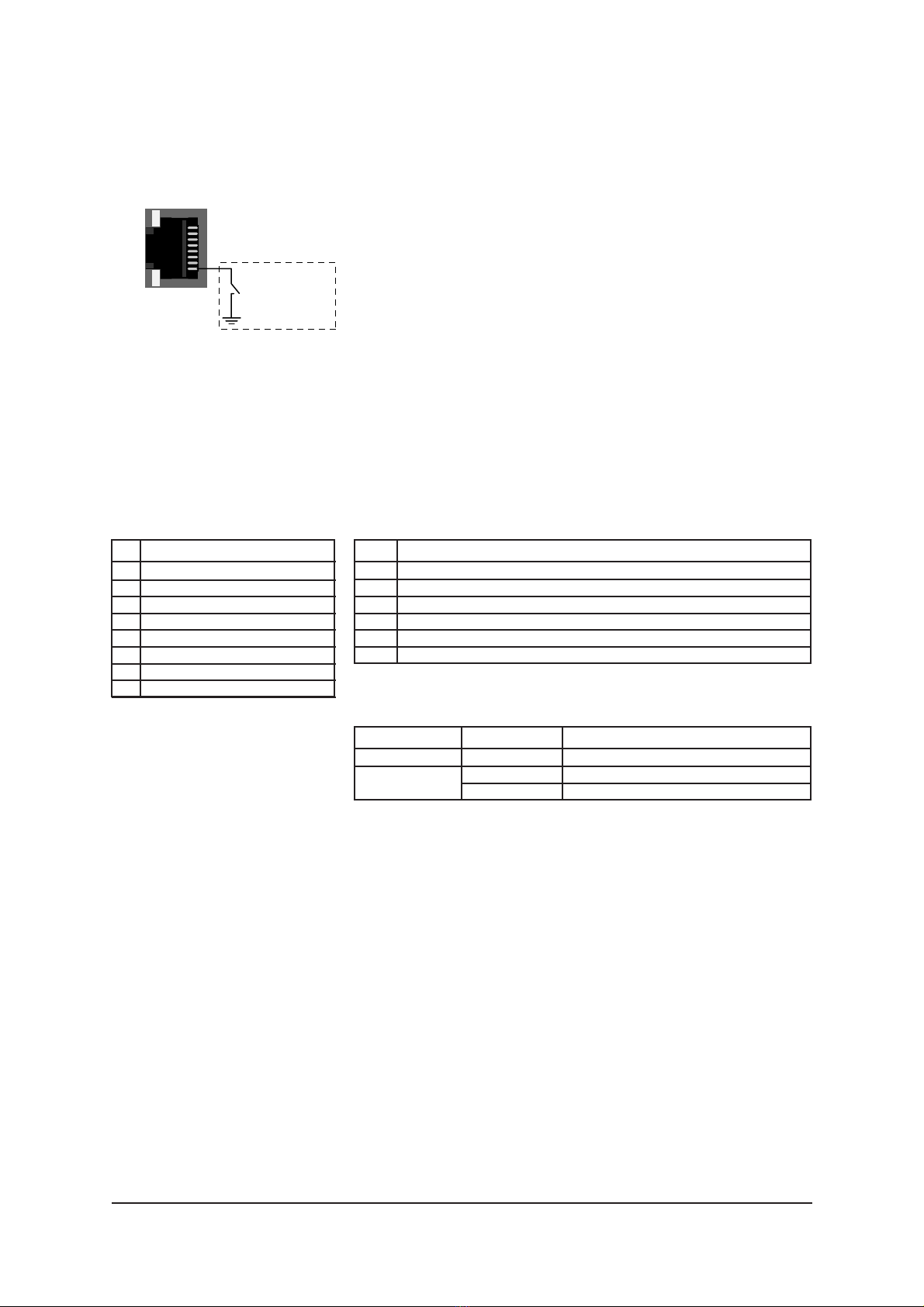
CONTACT CLOSURE LOOP (CCL) CONNECTION
The CCL connector contains one uni-directional contact
closure channel line
(TX --> RX)
. The CCL input is a normal
short circuit on/off - signal between connector’s contact pins 8
and ground (pins 1, 2, 5 or 6).
The CCL output is a normal output relay (dry contact) on/off -
signal between connector’s contact pins 3 and 4.
The connector in use is a RJ-45 female connector (see
picture 13 and table 31 for detailed description)
.
The recom-
mended cable for CCL connection is CIC603 (RJ-45 male/
open wires, see table 30 for detailed description).
The CCL IN/OUT leds indicates the status of CCL connection.
See table 32 for explanation of CCL connector’s leds.
The CCL output channel can be alternatively configured for
VSA usage
by using a PC and any terminal type communi-
cation software (see page 19)
.
The default factory setting is
CCL usage (CC1=CC1).
Table 32.
CCL connector’s leds / indicator lights (RJ-45 female).
Color Status
Green CCL output is closed
Yellow CCL output is open
Grey -
Led
CCL OUT
CCL IN
Table 31.
CCL connector’s pinout (RJ-45 female).
Pin Wire color
1 White / orange stripe
2 Orange
3 White / green stripe
4 Blue
5 White / blue stripe
6 Green
7 White / brown stripe
8 Brown
Table 30.
CIC603 cable’s pinout / wire
colors (RJ-45 male / open wires).
Pin Signal
1 Ground
2 Ground
3 CCL output (output relay)
4 CCL output (output relay)
5 Ground
6 Ground
7 NC
CCL output
connection
CCL
OUTIN
1
3
4
8
10 CVM 4ch video modem user manual rev001

LINK STATUS AND MODULE INDICATOR LEDS
When the optical input signal level is adequate and in syncron-
ization to input data is achieved, the LINK STATUS led on the
front panel is green. If optical input signal level is adequate,
but no syncronization is achieved the LINK STATUS led blinks
green/yellow. If optical input signal is missing or it’s level is too
low, the the LINK STATUS led is yellow.
When the supply voltage is not in the permitted range
(10.5...14 V DC) or there is a transmitter laser failure, the
MODULE led colour on the front panel is red. During normal
operation MODULE led is blinking green (blinking indicates
embedded software is working properly).
ALARM CONNECTIONS
All alarms at the rear connector of the unit are low open
collector outputs, with the capability of 30 V/10 mA
switching.
Table 33.
Open collector alarms.
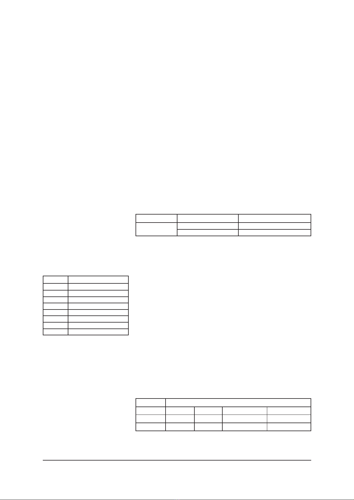
Note! At the rear of unit is located a DIP switch for factory
use only (see example picture below). If this switch is set
to “Program” (lower position), the unit goes to “program-
ming state” and then has no normal operation. Default fac-
tory setting is “Normal” (lower position).
Alarm Description Reason
A Hardware failure TX laser failure
Supply voltage is not in the permitted range
B Link status alarm Input optical signal is too low
No syncronisation archieved to input data
Y (ch 1) VIDEO 1
VIDEO 2
VIDEO 3
VIDEO 4
C (ch 2)
Composite video (ch 3)
CSX signal (ch 4)
Program
Normal
Note!The DIP switch at rear isfor factory use only.
If thisswitch isset to "Program" (upper position),
the unit goesto "programming state" and then has
no normal operation. Default factory setting is
"Normal" (lower position).
Switch existsin all units(transmitter & receiver).
DIP swithesfor Data/S-video
settings(only in transmitter)
LEFT SIDE VIEW
FRONT
CVM 4ch video modem user manual rev001 11

VIDEO SOURCE ALARM (VSA)
The CCL output channel can be alternatively configured for
VSA usage. In receiver units the VSA is only monitored by the
transmitter’s video input. When VSA mode is enabled and
transmitter’s video input is missing
(link otherwise operates
normally, but e.g. only the camera is broken)
, the CCL OUT
led blinks yellow and CCL output pins are closed. The VSA
function can be set on/off
by using a PC and any terminal type
communication software (see page 19).
The default factory
setting is CCL usage (CC1=CC1).
See table 35 for explanation of CCL connector’s OUT led
when VSA function is set active.
Note! Video detection has 20 sec delay before VIDEO
SOURCE ALARM is activated / inactivated.
Color Status
Green on/off blinking Video OK
Yellow on/off blinking Video missing
Led
CCL OUT
Table 35. CCL connector (RJ-45 female) / CCL OUT indicator led
when VSA is enabled.
FIBRE CONNECTION
Depending on the model, the CVM unit operates either on
standard 1310 or 1550 nm wavelenghts or ITU CWDM
wavelenghts from 1471 nm (C11) to 1611 nm (C18) with 20
nm spacing.
All optical port connectors are of type SC/APC
8° female. The nominal optical input level is -1 dBm. Available
optical link budget is 29 dB (see table 36).
When installing the fibre optic cable, do not exceed the mini-
mum bending radius when connecting cable to the system.
For correct optical operation ensure that:
* Protect opened connectors always with dustcaps
* Use only 8° angle polished SC/APC connectors
* Clean all connectors before mating by using metyl or
isopropyl alcocol and dry connectors by compressed air
ITU Ch Wavelength
11 1471 nm
12 1491 nm
13 1511 nm
14 1531 nm
15 1551 nm
16 1571 nm
17 1591 nm
18
1611 nm
Table 34.
Available ITU G.694.2 wavelength
channels for CVM units.
Optical output / min input / max input level dBm
Unit Standard Premium Standard + APD Premium + APD
CVM 4 TX 3 / - / - - - -
CVM 4 RX -/ -26 / -1 - - -
Table 36.
Optical levels for for CVM units.
12 CVM 4ch video modem user manual rev001
Other manuals for CFO OP-X series
1
Table of contents
Other Teleste Transmitter manuals


