SMAR LD291 Manual

INTELLIGENT PRESSURE TRANSMITTER
LD291
Version 6
MAR / 12
LD291ME

web: www.smar.com/contactus.asp
www.smar.com
Specifications and information are subject to change without notice.
Up-to-date address information is available on our website.
smar

Introduction
III
INTRODUCTION
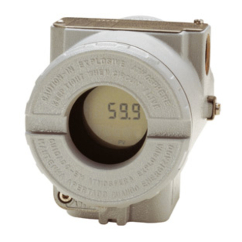
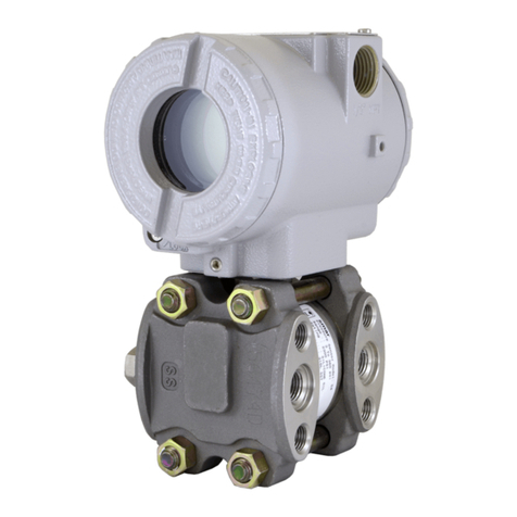
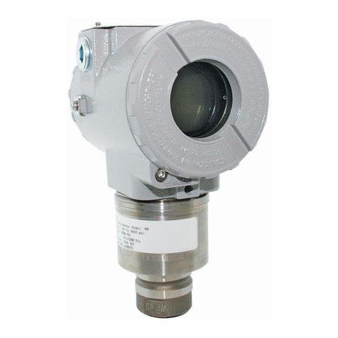
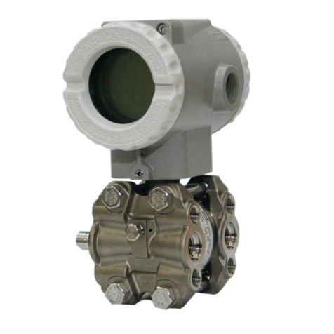
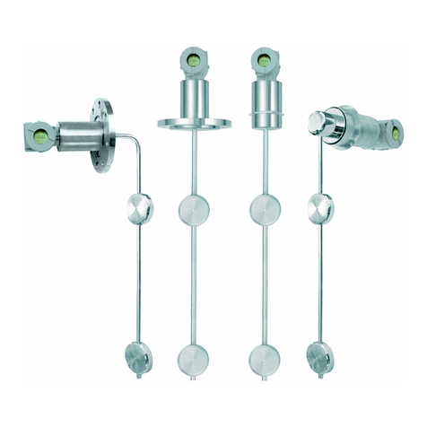
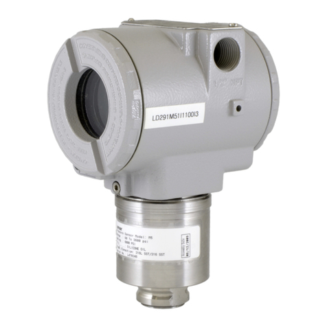
The LD291 is a smart pressure transmitter for gauge and level measurement. It is based on a
field-proven capacitive sensor that provides reliable operation and high performance. The digital
technology used in the LD291 enables an easy interface between the field and the control room and
several interesting features that considerably reduce the installation, operation and maintenance
costs.
The LD291 is the economical alternative in routine gage pressure measurement. This lightweight
design eliminates the need for mounting brackets and transmitter supports in many applications.
The model LD291 offers digital HARTbased communication simplifying calibration and providing
remote diagnostics. Also, an optional LCD meter can be added to provide additional operations and
local indication.
Its microprocessor- based electronics allow for total interchangeability with SMAR capacitive
sensors. It automatically corrects sensor characteristic changes caused by temperature fluctuations.
The LD291, besides the normal functions offered by other smart transmitters, offers the following
functions:
TABLE - the pressure signal is custom linearized according to a 16-point table, enabling, e.g.,
conversion of level to volume of a horizontal cylindrical tank.
LOCAL ADJUSTMENT - not only for lower and upper value, but input/output function,
indication, as well.
PASSWORD - three levels for different functions.
OPERATION COUNTER - shows the number of changes in each function.
USER-UNIT - indication in engineering unit of the property actually measured, e.g., level, flow or
volume.
WRITE-PROTECT- via hardware.
Get the best results of the LD291 by carefully reading these instructions.
Smar’s pressure transmitters are protected by U.S. patents 6,433,791 and 6,621,443.

LD291 - Operation and Maintenance Instruction Manual
IV
NOTE
This manual is compatible with version 6.XX, where 6 denote software version and XX software
release. The indication 6.XX means that this manual is compatible with any release of software
version 6.
WARNING
To ensure that our products are safe and without risk to health, the manual must be read carefully
before proceeding and warning labels on packages must be observed. Installation, operation,
maintenance and servicing must only be carried out by suitably trained personnel and in
accordance with the Operation and Maintenance Instruction Manual.
Waiver of responsibility
The contents of this manual abides by the hardware and software used on the current equipment
version. Eventually there may occur divergencies between this manual and the equipment. The
information from this document are periodically reviewed and the necessary or identified corrections
will be included in the following editions. Suggestions for their improvement are welcome.
Warning
For more objectivity and clarity, this manual does not contain all the detailed information on the
product and, in addition, it does not cover every possible mounting, operation or maintenance
cases.
Before installing and utilizing the equipment, check if the model of the acquired equipment complies
with the technical requirements for the application. This checking is the user’s responsibility.
If the user needs more information, or on the event of specific problems not specified or treated in
this manual, the information should be sought from Smar. Furthermore, the user recognizes that the
contents of this manual by no means modify past or present agreements, confirmation or judicial
relationship, in whole or in part.
All of Smar’s obligation result from the purchasing agreement signed between the parties, which
includes the complete and sole valid warranty term. Contractual clauses related to the warranty are
not limited nor extended by virtue of the technical information contained in this manual.
Only qualified personnel are allowed to participate in the activities of mounting, electrical connection,
startup and maintenance of the equipment. Qualified personnel are understood to be the persons
familiar with the mounting, electrical connection, startup and operation of the equipment or othe
r
similar apparatus that are technically fit for their work. Smar provides specific training to instruct and
qualify such professionals. However, each country must comply with the local safety procedures,
legal provisions and regulations for the mounting and operation of electrical installations, as well as
with the laws and regulations on classified areas, such as intrinsic safety, explosion proof, increased
safety and instrumented safety systems, among others.
The user is responsible for the incorrect or inadequate handling of equipments run with pneumatic
or hydraulic pressure or, still, subject to corrosive, aggressive or combustible products, since thei
r
utilization may cause severe bodily harm and/or material damages.
The field equipment referred to in this manual, when acquired for classified or hazardous areas, has
its certification void when having its parts replaced or interchanged without functional and approval
tests by Smar or any of Smar authorized dealers, which are the competent companies for certifying
that the equipment in its entirety meets the applicable standards and regulations. The same is true
when converting the equipment of a communication protocol to another. In this case, it is necessary
sending the equipment to Smar or any of its authorized dealer. Moreover, the certificates are
different and the user is responsible for their correct use.
Always respect the instructions provided in the Manual. Smar is not responsible for any losses
and/or damages resulting from the inadequate use of its equipments. It is the user’s responsibility to
know and apply the safety practices in his country.

Table of Contents
V
TABLE OF CONTENTS
SECTION 1 - INSTALLATION................................................................................................................ 1.1
GENERAL....................................................................................................................................................... 1.1
MOUNTING..................................................................................................................................................... 1.1
ELECTRONIC HOUSING............................................................................................................................... 1.8
WIRING........................................................................................................................................................... 1.9
LOOP CONECTIONS................................................................................................................................... 1.10
INSTALLATION IN HAZARDOUS AREAS................................................................................................... 1.12
EXPLOSION/FLAME PROOF ...................................................................................................................... 1.12
INTRINSICALLY SAFE................................................................................................................................. 1.12
SECTION 2 - OPERATION..................................................................................................................... 2.1
FUNCTIONAL DESCRIPTION - SENSOR..................................................................................................... 2.1
FUNCTIONAL DESCRIPTION - HARDWARE............................................................................................... 2.2
FUNCTIONAL DESCRIPTION - SOFTWARE................................................................................................ 2.3
THE DISPLAY................................................................................................................................................. 2.5
SECTION 3 - CONFIGURATION............................................................................................................ 3.1
CONFIGURATION FEATURES...................................................................................................................... 3.3
MANUFACTURING DATA AND IDENTIFICATION ....................................................................................... 3.3
PRIMARY VARIABLE TRIM - PRESSURE.................................................................................................... 3.3
PRIMARY VARIABLE CURRENT TRIM ........................................................................................................ 3.4
TRANSMITTER ADJUSTMENT TO THE WORKING RANGE...................................................................... 3.5
ENGINEERING UNIT SELECTION................................................................................................................ 3.6
TABLE POINTS.............................................................................................................................................. 3.7
EQUIPMENT CONFIGURATION ................................................................................................................... 3.8
EQUIPMENT MAINTENANCE ....................................................................................................................... 3.8
SECTION 4 - PROGRAMMING USING LOCAL ADJUSTMENT........................................................... 4.1
THE MAGNETIC TOOL.................................................................................................................................. 4.1
SIMPLE LOCAL ADJUSTMENT..................................................................................................................... 4.2
ZERO AND SPAN RERANGING.................................................................................................................... 4.2
COMPLETE LOCAL ADJUSTMENT.............................................................................................................. 4.3
LOCAL PROGRAMMING TREE..................................................................................................................... 4.3
CONFIGURATION [CONF]............................................................................................................................. 4.3
CONFIGURATION BRANCH (CONF)............................................................................................................ 4.4
RANGE (RANGE)........................................................................................................................................... 4.5
RANGE BRANCH (RANGE)........................................................................................................................... 4.5
FUNCTION (FUNCT)...................................................................................................................................... 4.7
PRESSURE TRIM [TRIM]............................................................................................................................... 4.8
ESCAPE LOCAL ADJUSTMENT [ESC]....................................................................................................... 4.10
SECTION 5 - MAINTENANCE PROCEDURES..................................................................................... 5.1
GENERAL....................................................................................................................................................... 5.1
DIAGNOSTIC WITH THE CONFIGURATOR................................................................................................. 5.1
ERROR MESSAGES...................................................................................................................................... 5.1
DIAGNOSTIC WITH THE TRANSMITTER .................................................................................................... 5.2
DISASSEMBLY PROCEDURE....................................................................................................................... 5.4
REASSEMBLY PROCEDURE........................................................................................................................ 5.5
INTERCHANGEABILITY ................................................................................................................................ 5.5
RETURNING MATERIALS............................................................................................................................. 5.6
ORDERING CODE FOR SENSOR ................................................................................................................ 5.9
SECTION 6 - TECHNICAL CHARACTERISTICS.................................................................................. 6.1
ORDERING CODE......................................................................................................................................... 6.4
OPTIONAL ITEMS.......................................................................................................................................... 6.5

LD291 - Operation and Maintenance Instruction Manual
VI
OPTIONAL ITEMS.......................................................................................................................................... 6.7
OPTIONAL ITEMS.......................................................................................................................................... 6.9
OPTIONAL ITEMS........................................................................................................................................ 6.11
APPENDIX A - CERTIFICATIONS INFORMATIONS............................................................................A.1
EUROPEAN DIRECTIVE INFORMATION.....................................................................................................A.1
OTHER APROVALS.......................................................................................................................................A.1
FMEDA REPORT....................................................................................................................................................... A.1
HAZARDOUS LOCATIONS CERTIFICATIONS ............................................................................................A.1
NORTH AMERICAN CERTIFICATIONS.................................................................................................................... A.1
EUROPEAN CERTIFICATIONS................................................................................................................................ A.2
SOUTH AMERICAN CERTIFICATIONS.................................................................................................................... A.2
ASIAN CERTIFICATIONS ......................................................................................................................................... A.3
IDENTIFICATION PLATE AND CONTROL DRAWING.................................................................................A.3
IDENTIFICATION PLATE.......................................................................................................................................... A.3
CONTROL DRAWING............................................................................................................................................... A.7
APPENDIX B – SRF – SERVICE REQUEST FORM .............................................................................B.1
APPENDIX C – SMAR WARRANTY CERTIFICATE.............................................................................C.1

Installation Flowchart
VII
Was the transmitter
configured on the bench
to match the application?
Configure the transmitter
(Section 1 and 3)
Configure the Fail-Safe
value (Section 3 - Configuration)
Configure the Damping
(Section 3 )- Configuration
Configure the LCD reading
(Section 3 )- Configuration
Apply the pressure
Is the reading correct?
See manual
(Section 5 )- Maintenance
Start
No
Yes
OK
Apply the Zero Trim
Is the impulse line wett leg?
Install the transmitter on the field
following the instructions below.
Install the transmitter preferably
on weather- protected areas.
Install the transmitter (mechanically
and electrically) according to the
application after checking the best
position for the LCD
(Section 5 )- Maintenance
Check the area classification
and its practices
Power the transmitter properly.
Did you correct the
transmitter reading?
Is the transmitter
reading correct?
Yes No
No
Yes
Yes
No
Yes
No
Configure the measuring range
to 0% (4mA) and 100% (20mA)
(Section 3 - Configuration)
Configure the engineering unit
(Section 3 - Configuration)

LD291 - Operation and Maintenance Instruction Manual
VIII

Section 1
1.1
INSTALLATION
General
NOTE
The installation carried out in hazardous areas should followthe recommendationsof theIEC60079-
14 standard.
The overall accuracy of a flow, level, or pressure measurement dependson severalvariables.Although
the transmitter has an outstanding performance, proper installation is essential to maximize its
performance.
Among all factors, which may affect transmitter accuracy, environmental conditions are the most
difficult to control. There are, however, ways of reducing the effects of temperature, humidity and
vibration.
The LD291 has a built-in temperature sensor to compensate for temperature variations. At thefactory,
each transmitter is submitted to a temperature cycle, and the characteristics under different
temperatures are recorded in the transmitter memory. At the field, this feature minimizes the
temperature variation effect.
Mounting
Putting the transmitter in areas protected from extreme environmental changes can minimize
temperature fluctuation effects.
In warm environments, the transmitter should be installed to avoid, as much as possible, direct
exposure to the sun. Installation close to lines and vessels subjected to high temperatures should also
be avoided. Use longer sections of impulse piping between tap and transmitter whenever the process
fluid is at high temperatures. Use of sunshades or heat shields to protect the transmitter from external
heat sources should be considered, if necessary.
Proper winterization (freeze protection) should be employed to prevent freezing within the measuring
chamber, since this will result in an inoperative transmitter and could even damage the cell.
Although the transmitter is virtually insensitive to vibration, installation closeto pumps, turbines orother
vibrating equipment should be avoided.
The transmitter has been designed to be both rugged and lightweight at the same time. This make its
mounting easier mounting positions are shown in Figure 1.1.
Should the process fluid contain solids in suspension, install valves or rod-out fittings at regular
intervals to clean out the pipes.
The pipes should be internally cleaned by using steam or compressed air, or by draining the line with
the process fluid, before such lines are connected to the transmitter (blow-down).
NOTE
When installing or storing the level transmitter, the diaphragm must be protected avoid scratching-
denting or perforation of its surface.

LD291 - Operation and Maintenance Instruction Manual
1.2
Figure 1.1(a) – Dimensional Drawing and Mounting Position for LD291

Installation
1.3
Figure 1.1(b) – Dimensional Drawing and Mounting Position for LD291 - Sanitary

LD291 - Operation and Maintenance Instruction Manual
1.4
Figure 1.1(c) – Dimensional Drawing and Mounting Position for LD291 – Sanitary

Installation
1.5
Figure 1.1(d) – Dimensional Drawing and Mounting Position for LD291 – Level

LD291 - Operation and Maintenance Instruction Manual
1.6
ELECTRIC
CONNECTION
FIXED
Sanitary
ADJUSTABLE
Diaphragm protection VIEW BY ‘’A’’
MOUNTING
BRACKET IN ‘ L’’‘
ADJUSTABLE
(OPTIONAL) O’RING
Mobile adjusting flange
VIEW BY ‘’BB’’
Mobile fixing flange
Flange process tank
FIXED
VIEW BY ‘’D’’
MACHINING DETAIL
OF FLANGE
4 M8 Screws
VIEW BY ‘’C’’
- DIMENSIONS ARE IN mm (in)
PROBE
LENGTH
Diaphragm protection with screen
Figure 1.1 (e) – Dimensional Drawing and Mounting Position for LD291 – Level (Insertion)

Installation
1.7
The figure 1.2 shows how to use the tool to fix the process transmitter tap.
Figure 1.2 – Fixing of the Transmitter in the Tap
Observe operating safety rules during wiring, draining or blow-down.
WARNING
Normal safety precautions must be taken to avoid the possibility of an accident occurring when
operating in conditions of high pressure and/or temperature.
Electrical shock can result in death or serious injury.
Avoid contact with the leads and terminals.
Process leaks could result in death or serious injury
Do not attempt to loosen or remove flange bolts while the transmitter is in service.
Replacement equipment or spare parts not approved by Smar could reduce the pressure
retaining capabilities of the transmitter and may render the instrument dangerous.
Use only bolts supplied or sold by Smar as spare parts.
Some examples of installation, illustrating the position of the transmitter in relation to the taps, are
shown in Figure 1.3.
The location of pressure taps and the relative position of the transmitter are indicated in Table 1.1.
Process Fluid Location of Taps Location of LD291 in Relation to the Taps
Gas Top or Side Above the Taps.
Liquid Side Below the Taps or at the Piping Centerline.
Steam Side Below the Taps using Sealing (Condensate) Pots.
Table 1.1 - Location of Pressure Taps
NOTE
Except for dry gases, all impulse lines should slope at the ratio 1:10, in order to avoid trapping
bubbles in the case of liquids, or condensate for steam or wet gases.

LD291 - Operation and Maintenance Instruction Manual
1.8
GAS
STEAM
LIQUID
Figure 1.3 – Position of the Transmitter and Taps
NOTE
The transmitters are calibrated in the vertical position and a different mounting position displaces
the zero point. Consequently, the indicator will indicate a different value from the applied pressure.
In these conditions, it is recommended to do the zero pressure trim. The zero trim is to compensate
the final assembly position and its performance, when the transmitter is in its final position. When
the zero trim is executed, make sure the equalization valve is open and the wet leg levels are
correct.
For the absolute pressure transmitter, the assembly effects correction should be done using the
Lower trim, due to the fact that the absolute zero is the reference for these transmitters, so there is
no need for a zero value for the Lower trim.
Electronic Housing
Humidity is fatal to electronic circuits. In areas subjected to high relative humidity, the O-rings for the
electronic housing covers must be correctly placed and the covers must be completely closed by
tighten them by hand until you feel the O-rings being compressed. Do not use toolstoclose thecovers.
Removal of the electronics cover in the field should be reduced to the minimum necessary, since each
time it is removed; the circuits are exposed to the humidity.
The electronic circuit is protected by a humidity proof coating, but frequent exposures to humiditymay
affect the protection provided. Itis also important to keep the covers tightened inplace. Everytime they
are removed, the threads are exposed to corrosion, since painting cannot protect these parts. Code-
approved sealing methods should be employed on conduit entering the transmitter.
WARNING
The unused cable entries should be plugged and sealed accordingly to avoid humidity entering,
which can cause the loss of the product’s warranty.
DIAPHRAGM
SENSOR IN THE VERTICAL
SENSOR IN THE HORIZONTAL
HEAD OF THE FLUID
DIAPHRAGM

Installation
1.9
The electronic housing can be rotated to adjust the digital display on a better position. To rotate it,
loose the Housing Rotation Set Screw, see Figure 1.4 (a). To prevent humidity entering, the electric
housing and the sensor joint must have a minimum of 6 fully engaged threads. The provided joint
allows 1 extra turn to adjust the position of the display windowby rotating the housing clockwise. If the
thread reaches the end before the desired position, then rotate the housingcounterclockwise, but not
more than one thread turn. Transmitters have a stopper that restricts housing rotation to one turn. See
Section 4, Figure 4.1.
COVER
LOCKING
SCREW
(a)
(b)
Figure 1.4 - Cover Locking and Housing Rotating Set Screw (a) Electronic Board Side
(b) Terminal Connection Side
Wiring
To release the coverthat gives access to the wiring block, turn the cover locking screw clock wise, see
the direction of the arrow in the figure 1.4.
Test and Communication terminals allow, respectively, to measure the current in the 4 -20 mAloop,
without opening it, and to communicate with the transmitter. To measure it,connect a multimeterinthe
mA scale in the "-" and "+" terminals, and to communicate, use a HART configurator in the "COMM"
and "-" terminals. The wiring block has screws on which fork or ring-type terminals can be fastened.
See Figure 1.6.
Figure 1.5– Wiring Block
The LD291 is protected against reverse polarity
For convenience there are two ground terminals: one inside the coverand one external, located close
to the conduit entries.
Use of twisted pair (22 AWG or greater than) cables is recommended. Avoid routing signal wiringclose
to power cables or switching equipment.
The Figure 1.6 shows the correct installation of the conduit, to avoid penetration of water, or other
substance, which may cause malfunctioning of the equipment.
COMUNICATION
TERMINAL
LOC
TES
COM
+
TES
TERMINAL
GROUND
TERMINA

LD291 - Operation and Maintenance Instruction Manual
1.10
CORRECT
WIRES INCORRECT
Figure 1.6 - Conduit Installation
Loop Conections
Connection of the LD291 should be done as in Figure 1.7. Connection in multi-drop configuration
should be done as in Figure 1.8. Note that a maximum of 15 transmitters can be connected on the
same line and that they should be connected in parallel.
Take care to the power supply as well, when many transmitters are connected on the same line. The
current through the 250 Ohm resistor will be high causing a high voltage drop. Therefore make sure
that the power supply voltage is sufficient.
The configuration can be connected to the communication terminals of thetransmitteror atanypoint of
the signal line by using the alligator clips. It is also recommended to ground the shield of shielded
cables at only one end. The ungrounded end must be carefully isolated.
250
SIGNAL LOOP BE GROUNDED ATANY
POINT OR LEFT UNGROUND
CONFIGURATOR
POWER
SUPPLY
Figure 1.7 – Wiring Diagram for the LD291
POWER
SUPPLY
113 14 15*
CONFIGURATOR
250
Figure 1.8 – Wiring Diagram for the LD291 in Multidrop Configuration

Installation
1.11
NOTE
Make sure that the transmitter is operating within the operating area as shown on the load curve
(Figure 1.9). Communication requires a minimum load of 250 Ohm.
Figure 1.9 – Load Curve

LD291 - Operation and Maintenance Instruction Manual
1.12
Installation in Hazardous Areas
WARNING
Explosions could result in death or serious injury, besides financial damage. Installation of this
transmitter in explosive areas must be carried out in accordance with the local standards and the
protection type adopted .Before continuing the installation make sure the certificate parameters are I
n accordance with the classified area where the equipment will be installed.
The instrument modification or parts replacement supplied by otherthan authorizedrepresentative of
Smar is prohibited and will void the certification.
The transmitters are marked with options of the protection type. The certification is valid only when
the protection type is indicated by the user.Once a particular type of protection is selected, any other
type of protection can not be used.
The electronic housing and the sensor installed in hazardous areas must have a minimum of 6 fully
engaged threads. Lock the housing using the locking screw (Figure 1.4).
The cover must be tightened with at least 8 turns to avoid the penetration of humidity or corrosive
gases. The cover must be tightened until it touches the housing. Then, tighten more 1/3 turn (120°)to
guarantee the sealing. Lock the covers using the locking screw (Figure 1.4).
Consult the Appendix A for further information about certification.
Explosion/Flame Proof
WARNING
In Explosion-Proof installations the cable entries must be connected or closed using metal cable
gland and metal blanking plug, both with at least IP66 and Ex-d certification.
As the transmitter is non-ignition capable under normal conditions, the statement “Seal not
Required” could be applied for Explosion Proof Version (CSA Certification).
The standard plugs provided by Smar are certified according to the standards at FM, CSA and
CEPEL. If the plug needs to be replaced, a certified plug must be used.
The electrical connection with NPT thread mustusewaterproofingsealant. Anon-hardeningsilicone
sealant is recommended.
Do not remove the transmitter covers when power is ON.
Intrinsically Safe WARNING
In hazardous zones with intrinsically safe or non-incendive requirements, the circuit entity
parameters and applicable installation procedures must be observed.
To protect the application the transmitter must be connected to a barrier. Match the parameters
between barrier and the equipment (Considerthe cableparameters).Associated apparatus ground
bus shall be insulated from panels and mounting enclosures. Shield is optional. If used, be sure to
insulate the end not grounded. Cable capacitance and inductance plus Ciand Limust be smaller
than Co and Lo of the associated Apparatus.
For free access to the Hart bus in the explosive environment, ensure the instruments in the loop
are installed in accordance with intrinsically safe or non-incendive field wiring practices. Use only
Ex Hart communicator approved according to the type of protection Ex-i (IS) or Ex-n (NI).
It is not recommended to remove the transmitter cover when the power is ON.
Other manuals for LD291
1
Table of contents
Other SMAR Transmitter manuals
Popular Transmitter manuals by other brands
YOKOGAWA
YOKOGAWA DpharpEJX vigilantplant EJX210A user manual
Emerson
Emerson Rosemount 3051S Series Reference manual
Honeywell
Honeywell Midas S2 user manual

RKI Instruments
RKI Instruments 65-2330RKSS Operator's manual

PSM
PSM APT 500 Series Installation, Operation & Maintenance Instruction Manual

Campbell
Campbell SAT HDR GOES instruction manual
Macurco
Macurco TracXP TXP-WTA instruction manual
Moore Industries
Moore Industries TMZ user manual

Becker
Becker Centronic MemoControl MC511 Assembly and operating instructions
Acromag
Acromag 655T-06003-C user manual

Phonak
Phonak Roger WallPilot user guide
Broadcast Electronics
Broadcast Electronics STXe Series Technical manual
