Teletask TDS20065 User manual

TDS20065
Quick Installation Guide

TDS20065
L8 – HVAC Line 8 (USB Host)
Power
L1 – HVAC Line 1
Ethernet Port
L7 – HVAC Line 7
DIP Switches P, Q, R, S
LCD Touch Screen
L8 — HVAC Line 8 (USB Host)
Power
Power Plug
RS232 Port
L1 — HVAC Line 1
L2 — HVAC Line 2
RS485
Ethernet Port
GPIOs
L7 — HVAC Line 7
L6 — HVAC Line 6
L5 — HVAC Line 5
L4 — HVAC Line 4
USB Device Port
DIP Switches P, Q, R, S
LCD Touch Screen
1 2 3 4
6
5
7
All Units
21 L1.101
23 L1.102
25 L1.103
25 L7.101
MACADDR00001
L6 L8L5L4L3L2
192.168.0.1
cj 9/10 LG PQW
All O
1
2
3
4
5
6
7
HVAC Daikin VRV — on L1
1 HVAC Communication Terminals
Connect to the communication terminals on
the HVAC equipment:
HVAC communication terminal’s names*
F1 Daikin **
Max. 64 indoor units
F2
* For Heat Recovery systems the connection is at
oudoor units only.
* Polarity is not required on the HVAC
communication line.
** Centralized (group) address required.
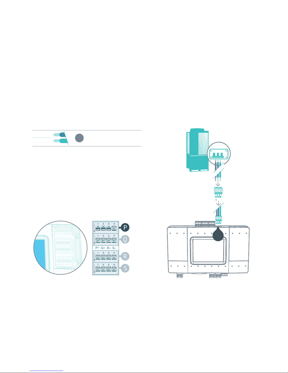
2 Connecting to the line plug
Secure the cables in the L1 line plug.
3 Plugging to the TDS20065
Insert the plug in to the TDS20065 L1
socket
4 Check DIP Switches are set correctly
Dip switches setup for VRV HVAC system on L1
DK
Daikin HVAC Terminal
L1
4
3
2
1

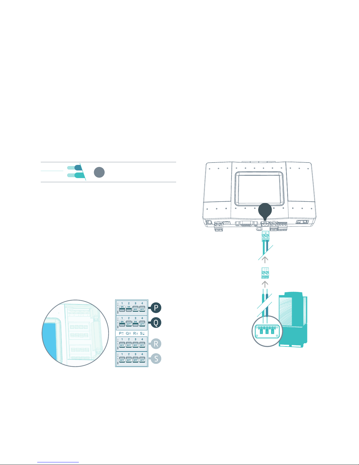
HVAC Mitsubishi Electric VRF — on L1
1 HVAC Communication Terminals
Connect to the communication terminals on
the HVAC equipment:
HVAC communication terminal’s names*
M1 Mitsubishi Electric
Max. 50 indoor units
M2
* For Heat Recovery systems the connection is at
outdoor units only.
* Polarity is not required on the HVAC
communication line.
2 Connecting to the line plug
Secure the cables in the L1 line plug.
3 Plugging to the TDS20065
Insert the plug in to the TDS20065 L1
socket
4 Check DIP Switches are set correctly
Dip switches setup for VRF HVAC system on L1
ME
L1
4
3
2
1
Mitsubishi Electric HVAC Terminal
HVAC Daikin Non-VRV — on L1
For Daikin Non-VRV equipment, DC voltage supply
by TDS20065 might be required for proper
operation.
Before enabling DC output from TDS20065 make sure
there is no DC voltage on HVAC communication line.
1 Measure DC voltage on HVAC communication
line L1
2 If no DC voltage . Daikin 14-16V DC change
the dip switches as shown below
3 Turn ON the power for TDS20065 and
connect it to HVAC line.
4 Connect to the communication terminals on
the HVAC equipment and secure the cables in
the L1 line plug.
5 Insert the plug in to the TDS20065 L1
socket.
Daikin Non-VRV HVAC Terminal
Changing the dip switches , while DC voltage is present on L1, may damage
the TDS20065.
L1
2
1
4
3
5

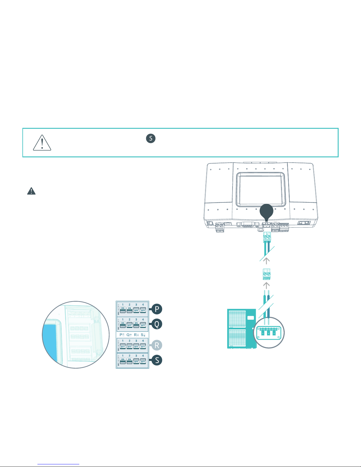
HVAC Mitsubishi Electric Non-VRF — on L1
For Mitsubishi Electric Non-VRF equipment,
DC voltage supply by TDS20065 might be
required for proper operation.
Make sure TDS20065 is disconnected
from power and HVAC line.
1 Measure DC voltage on HVAC communication
line L1
2 If no DC voltage . Mitsubishi 28-30V DC
change the dip switches as shown below
3 Turn ON the power for TDS20065 and
connect it to HVAC line.
4 Connect to the communication terminals on
the HVAC equipment and secure the cables in
the L1 line plug.
5 Insert the plug in to the TDS20065 L1
socket.
Mitsubishi Non-VRF HVAC Terminal
Changing the dip switches , while DC voltage is present on L1, may damage
the TDS20065.
L1
2
1
4
3
5

1 HVAC Communication Terminals
Connect to the communication terminals on
the HVAC equipment:
HVAC communication terminal’s names*
U1 Panasonic / Sanyo
Max. 64 indoor units
U2
* For Heat Recovery systems the connection is at
outdoor units only.
* Polarity is not required on the HVAC
communication line.
2 Connecting to the line plug
Secure the cables in the L1 line plug.
3 Plugging to the TDS20065
Insert the plug in to the TDS20065 L1
socket
4 Check DIP Switches are set correctly
Dip switches setup for VRF HVAC system on L1
PN
HVAC Panasonic/Sanyo VRF — on L1
Panasonic / Sanyo HVAC Terminal
L1
4
3
2
1

1 HVAC Communication Terminals
Connect to the communication terminals on
the HVAC equipment:
HVAC communication terminal’s names*
U1 Toshiba
Max. 64 indoor units
U2
* For Heat Recovery systems the connection is at
outdoor units only.
* Polarity is not required on the HVAC
communication line.
2 Connecting to the line plug
Secure the cables in the L1 line plug.
3 Plugging to the TDS20065
Insert the plug in to the TDS20065 L1
socket
4 Check DIP Switches are set correctly
Dip switches setup for VRF HVAC system on L1
TO
HVAC Toshiba VRF — on L1
Toshiba HVAC Terminal
L1
4
3
2
1

HVAC Hitachi (JCI) VRF — on L1
1 HVAC Communication Terminals
Connect to the communication terminals on
the HVAC equipment:
HVAC communication terminal’s names*
1Hitachi
Max. 160 indoor units
2
* For Heat Recovery systems the connection is at
outdoor units only.
* Polarity is not required on the HVAC
communication line.
2 Connecting to the line plug
Secure the cables in the L1 line plug.
3 Plugging to the TDS20065
Insert the plug in to the TDS20065 L1
socket
4 Check DIP Switches are set correctly
Dip switches setup for VRF HVAC system on L1
HT
Hitachi (JCI) HVAC Terminal
L1
4
3
2
1

HVAC York (US) VRF — on L1
1 HVAC Communication Terminals
Connect to the communication terminals on
the HVAC equipment:
HVAC communication terminal’s names*
1York (US)
Max. 164 indoor units
2
* For Heat Recovery systems the connection is at
outdoor units only.
* Polarity is not required on the HVAC
communication line.
2 Connecting to the line plug
Secure the cables in the L1 line plug.
3 Plugging to the TDS20065
Insert the plug in to the TDS20065 L1
socket
4 Check DIP Switches are set correctly
Dip switches setup for VRF HVAC system on L1
YK
York (US) HVAC Terminal
L1
4
3
2
1

L1
4
3
2
1
HVAC York VRF — on L1
1 HVAC Communication Terminals
Connect to the communication terminals on
the HVAC equipment:
HVAC communication terminal’s names*
PYork
Max. 64 indoor units
Q
* For Heat Recovery systems the connection is at
outdoor units only.
* Polarity is not required on the HVAC
communication line.
2 Connecting to the line plug
Secure the cables in the L1 line plug.
3 Plugging to the TDS20065
Insert the plug in to the TDS20065 L1
socket
4 Check DIP Switches are set correctly
Dip switches setup for VRF HVAC system on L1
YK
York HVAC Terminal

HVAC Haier VRF — on L1
1 HVAC Communication Terminals
Connect to the communication terminals on
the HVAC equipment:
HVAC communication terminal’s names*
PHaier
Max. 64 indoor units
Q
* For Heat Recovery systems the connection is at
outdoor units only.
* Polarity is not required on the HVAC
communication line.
2 Connecting to the line plug
Secure the cables in the L1 line plug.
3 Plugging to the TDS20065
Insert the plug in to the TDS20065 L1
socket
4 Check DIP Switches are set correctly
Dip switches setup for VRF HVAC system on L1
HA
Haier HVAC Terminal
L1
4
3
2
1
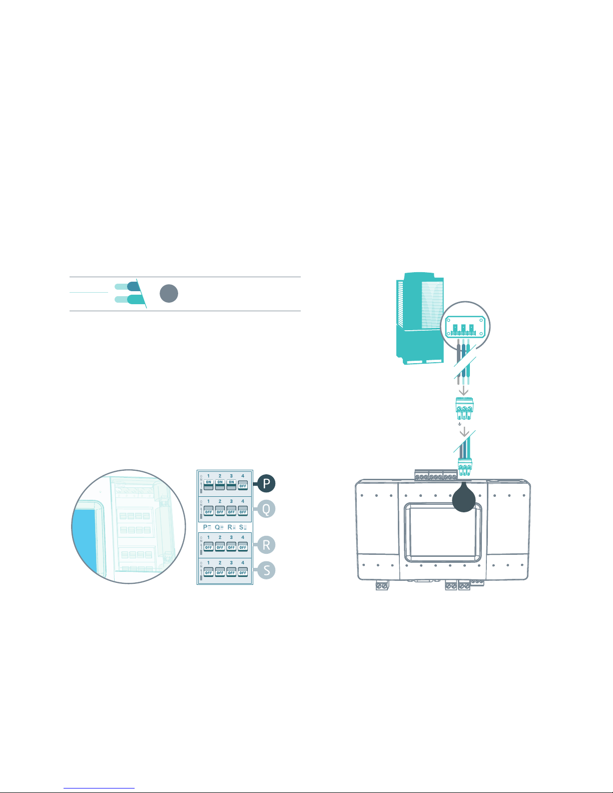
HVAC Mitsubishi Heavy VRF — on L7
1 HVAC Communication Terminals
Connect to the communication terminals on
the HVAC equipment:
HVAC outdoor or indoor
AMitsubishi Heavy
(Max. 128 indoor units)
B
2 Connecting to the line plug
Secure the cables in the L7 line plug.
3 Plugging to the TDS20065
Insert the plug in to the TDS20065 L7
socket
4 Check DIP Switches are set correctly
Dip switches setup for VRF HVAC system on L7
MH
Mitsubishi Heavy HVAC Terminal
L7
A B
4
3
2
1

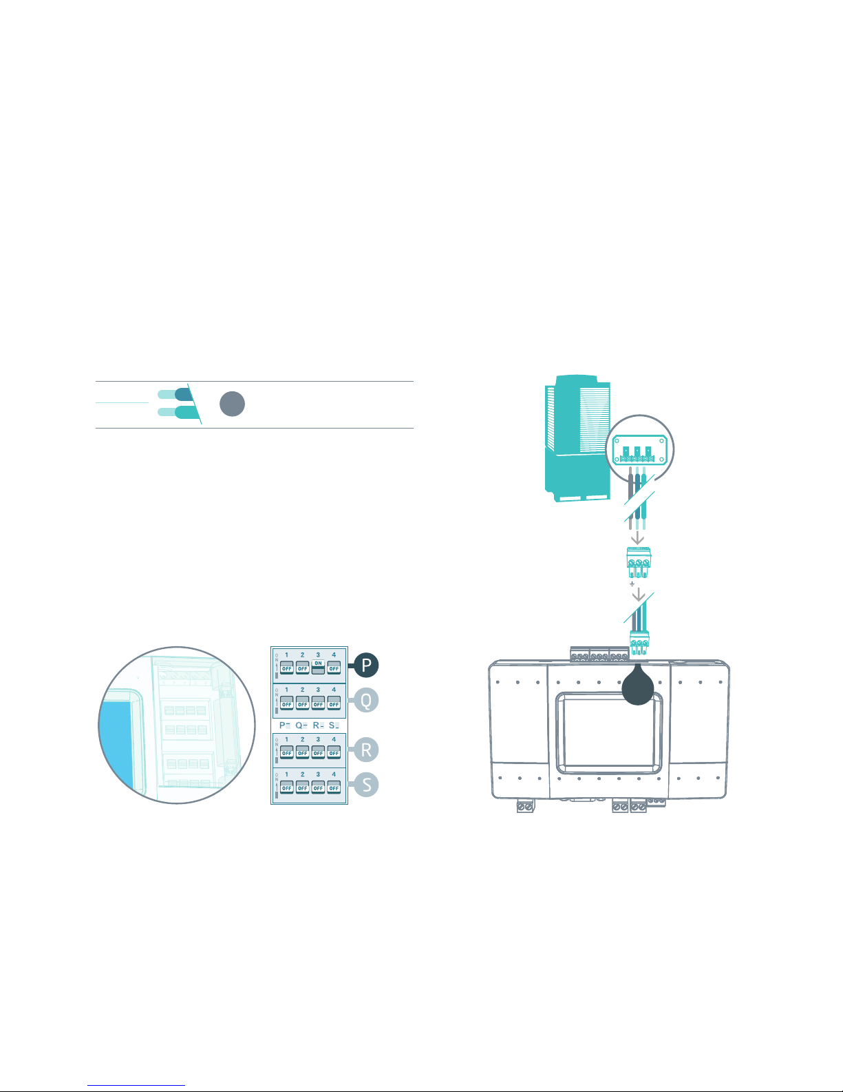
HVAC LG VRF — on L7
1 HVAC Communication Terminals
Connect to the communication terminals on
the HVAC equipment:
HVAC outdoor or indoor
InterA LG
(Max. 128 indoor units)
InterB
2 Connecting to the line plug
Secure the cables in the L7 line plug.
3 Plugging to the TDS20065
Insert the plug in to the TDS20065 L7
socket
4 Check DIP Switches are set correctly
Dip switches setup for VRF HVAC system on L7
LG
LG HVAC Terminal
L7
A B
4
3
2
1
HVAC Gree VRF — on L7
1 HVAC Communication Terminals
Connect to the communication terminals on
the HVAC equipment:
HVAC outdoor only
AGree
Max. 16 indoor units
B
2 Connecting to the line plug
Secure the cables in the L7 line plug.
3 Plugging to the TDS20065
Insert the plug in to the TDS20065 L7
socket
4 Check DIP Switches are set correctly
Dip switches setup for VRF HVAC system on L7
GR
Gree HVAC Terminal
L7
A B
4
3
2
1

HVAC Midea VRF — on L7
Midea HVAC Terminal
L7
A B
4
3
2
1
1 HVAC Communication Terminals
Connect to the communication terminals on
the HVAC equipment:
HVAC outdoor only
X
Midea
Max. 64 indoor units
Y
E
2 Connecting to the line plug
Secure the cables in the L7 line plug.
3 Plugging to the TDS20065
Insert the plug in to the TDS20065 L7
socket
4 Check DIP Switches are set correctly
Dip switches setup for VRF HVAC system on L7
MD

HVAC Samsung VRF — on L7
1 HVAC Communication Terminals
Connect to the communication terminals on
the HVAC equipment:
HVAC outdoor only
R1 Samsung
Max. 64 indoor units
R2
2 Connecting to the line plug
Secure the cables in the L7 line plug.
3 Plugging to the TDS20065
Insert the plug in to the TDS20065 L7
socket
4 Check DIP Switches are set correctly
Dip switches setup for VRF HVAC system on L7
SM
Samsung HVAC Terminal
L7
A B
4
3
2
1

L7
A B
4
3
2
1
HVAC Trane VRF — on L7
1 HVAC Communication Terminals
Connect to the communication terminals on
the HVAC equipment:
HVAC outdoor only
X
Trane
Max. 64 indoor units
Y
E
2 Connecting to the line plug
Secure the cables in the L7 line plug.
3 Plugging to the TDS20065
Insert the plug in to the TDS20065 L7
socket
4 Check DIP Switches are set correctly
Dip switches setup for VRF HVAC system on L7
TR
Trane HVAC Terminal
HVAC Trane (US) VRF — on L7
1 HVAC Communication Terminals
Connect to the communication terminals on
the HVAC equipment:
HVAC outdoor only
R1 Tane (US)
Max. 64 indoor units
R2
2 Connecting to the line plug
Secure the cables in the L7 line plug.
3 Plugging to the TDS20065
Insert the plug in to the TDS20065 L7
socket
4 Check DIP Switches are set correctly
Dip switches setup for VRF HVAC system on L7
TR
Trane (US) HVAC Terminal
L7
A B
4
3
2
1

HVAC Kentatsu VRF — on L7
1 HVAC Communication Terminals
Connect to the communication terminals on
the HVAC equipment:
HVAC outdoor only
X
Kentatsu
Max. 64 indoor units
Y
E
2 Connecting to the line plug
Secure the cables in the L7 line plug.
3 Plugging to the TDS20065
Insert the plug in to the TDS20065 L7
socket
4 Check DIP Switches are set correctly
Dip switches setup for VRF HVAC system on L7
KN
Kentatsu HVAC Terminal
L7
A B
4
3
2
1
Table of contents


