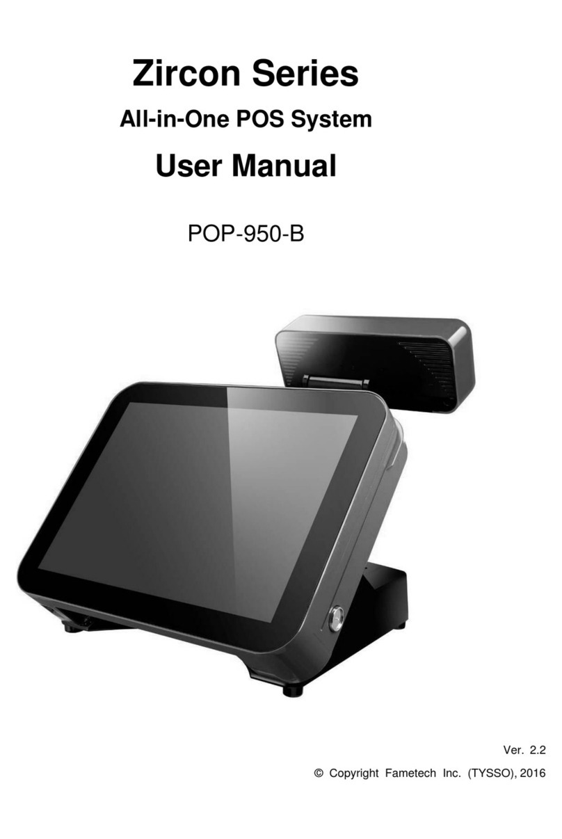
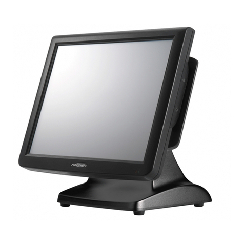
Fametech POS-3000 Series User manual

i
Service Manual
POS-3000 Series
5-Wire Resistive Touch Panel
POS System
POS-3000-D2550 / POS-3000-i/POS-3000-B
Ver. 2.1
© Copyright Fametech Inc. (TYSSO) 2015

ii
Table of Contents
IParts Description ...............................................................................4
AExamining Your System .............................................................................4
Exploded View........................................................................................................4
BParts Description ........................................................................................5
a. Cables .............................................................................................................6
b. Main Board...................................................................................................... 7
c. CPU Cooler Kit .............................................................................................. 12
d. RAM Module.................................................................................................. 12
e. Side I/O Board............................................................................................... 12
f. LCD Panel..................................................................................................... 13
II System Disassembly .......................................................................15
ADetach the Base from POS Unit...............................................................15
BDisassemble the POS Unit .......................................................................16
a. Remove the Back Cover................................................................................ 16
b. Remove the Hard Disk................................................................................... 17
c. Remove the Main Board Cover...................................................................... 18
d. Remove the MSR Kit (optional)...................................................................... 19
e. Disconnect the Inverter.................................................................................. 19
f. Remove the Power Switch............................................................................. 20
g. Disconnect the Touch Panel Connector ......................................................... 20
h. Remove the Side I/O Board........................................................................... 21
i. Disconnect the HDD Cable............................................................................ 21
j. Disconnect the LVDS Cable from the Main Board.......................................... 22
k. Disconnect the connectors of Power Indicator & Speakers ............................ 22
l. Remove the Main Board................................................................................ 23
m. Remove the RAM Module.............................................................................. 24
n. Remove the CPU Fan & Heat Sink................................................................ 25
o. Remove the Speakers, LVDS Cable and Power LED Indicator ...................... 26
p. Remove the I/O Bracket................................................................................. 27
q. Remove the LCD Panel................................................................................. 27
r. Remove the Touch Panel............................................................................... 28
CDisassemble Base Kit...............................................................................29
a. Remove the Power Adapter and Base........................................................... 29
b. Disassemble the Base Arm Set...................................................................... 30
iii
Table of Figures
Figure 1 Exploded View of the System............................................................................... 4
Figure 2 Cables..................................................................................................................6
Figure 3 Main board Layout- Front (POS-3000-D2550)......................................................8
Figure 4 Main board Layout- Front (POS-3000-i) ...............................................................9
Figure 5 Main board Layout- Front (POS-3000-B)............................................................ 10
Figure 6 Main board Layout- Back (POS-3000-B).............................................................11
Figure 7 CPU Fan & Heat Sink (POS-3000-D2550) ......................................................... 12
Figure 8 CPU Fan & Heat Sink (POS-300-i)..................................................................... 12
Figure 9 RAM Module ...................................................................................................... 12
Figure 10 Side I/O Board ................................................................................................... 12
Figure 11 LCD Panel.......................................................................................................... 13

4
I Parts Description
A Examining Your System
Exploded View
Figure 1 Exploded View of the System

5
B Parts Description
No.
Item
Description
1
Front Bezel
Front Bezel (Black, White or Red)
2
LED Indicator
Main Power LED Indicator
3
Sealing Rubber
Touch Panel Rubber
4
Touch Panel
5-Wire Resistive Touch Panel
5
LCD Panel
15-inch LCD Panel
6
Panel Chassis
LCD Panel Chassis
7
I/O Bracket
Bottom I/O Bracket
8-1
8-2
Speaker
Speakers
9
Side I/O Bracket
Side I/O and Power Switch Bracket
10
Power Switch
Main Power Switch
11
Side I/O Board
Side I/O Board (PS2/KB/USB)
12
Main Board
Main Board
13
Main Board Cover
Metal Main Board Cover
14
HDD Bracket
2.5”HDD/SSD Drive Bracket
14-1
HDD Mylar (Insulation Film)
Protective film of HDD Drive
15
Hard Disk Drive
2.5”SATA HDD (or SSD)
16
Back Cover
Back Cover of POS Unit
17
HDD Cover
Hard Disk Drive Cover
18
MSR Module (Optional)**
MSR Module
18-1
MSR Cover (Optional)**
Protective Cover when MSR NOT Installed
19
Antenna Plug
Dust Proof Rubber cap
20
Hinge Cover
Hinge Rear Cover
21
Hinge Holder
Hinge Holder
22
Base
Aluminum Base
23
Holder
Base Holder
24
Base Cover
Base Rear Cover
25
Swivel Set
Hinge Swivel x 2
26
Power Adapter
Power Adapter
27
Metal Holder
Metal Power Adapter Holder
* If the antenna is equipped, the protective plug will not be included in the system.
** The optional peripherals may not include in the system. Please contact the local
representatives or technical support personnel of the providers for further information.

6
a. Cables
HDD Cable
LVDS Cable
Power LED Indicator
Power Switch
Speakers
MSR Cable (optional)
Inverter Cable
I/O Board Cable
Figure 2 Cables

7
b. Main Board
●Main Board Connection / Installation Notes
The table below is the descriptions of the connectors of the main board.
Each connector/slot is used for the specified part or optional peripheral.
Please refer to the notes as below and examine the layouts of the main boards to locate
the correct connectors so as to complete the installation.
i.e.:
To connect the HDD to the main board, please use the HDD cable and locate the
matched connector on the main board; then connect the HDD cable to the Hard Drive.
No.
Connector/Slot
Connection/Installation Notes
1
HDD Connectors
Please use the HDD cable and connect to the Hard
drive. (Black: Data; White: HDD power)
2
Reserved*
Reserved* ( for Capacitive Touch Panel)
3
Connector of Side I/O Board
Connect to the Side I/O Board (PS/2 and USB)
4
Connector of Resistive Touch
Control Unit.
Connect to the Resistive Touch Panel
5
Connector of PWR Indicator
Connect the Power Indicator to the main board.
6
Connector of Power Switch
Connect the Power Switch to the main board.
7
LVDS Connector
Use the LVDS Cable and connect to the LCD Panel.
8
Audio Connector (Speaker)
Connect the Speaker to the main board.
9-1
Connector of Side I/O (MSR)
Connect the Side I/O Connector (MSR) to the main
board.
*Reserved for MSR/i-Button Module
9-2
Connector of Side I/O (USB)
Connect the Side I/O Connector (USB) to the main
board.
*Reserved for MSR/i-Button Module
10
Inverter Connector
Please use Inverter Cable and connect to the Inverter.
11
RAM Module Slot
Install the RAM module to the main board.
12
CPU FAN Connector
Install the CPU Cooler kit(CPU Fan & Heat Sink)

8
●POS-3000-D2550
Front View
Figure 3 Main board Layout- Front (POS-3000-D2550)
1
2
6
3
5
7
9-1
9-2
11
4
8
12
CPU
Fan
Connector
10

9
●POS-3000-i
Front View
Figure 4 Main board Layout- Front (POS-3000-i)
1
2
6
3
5
7
9-1
9-2
11
4
8
12
CPU
Fan
Connector
10

10
●POS-3000-B
Front View
Figure 5 Main board Layout- Front (POS-3000-B)
1
2
6
3
5
7
9-1
9-2
11
4
8
12
CPU
Fan
Connector
(Reserved)
10

11
Figure 6 Main board Layout- Back (POS-3000-B)
CFAST
Slot

12
c. CPU Cooler Kit
Figure 7
CPU Fan & Heat Sink (POS-3000-D2550/POS-3000-B)
Figure 8
CPU Fan & Heat Sink (POS-300-i)
d. RAM Module
Figure 9 RAM Module
e. Side I/O Board
Figure 10 Side I/O Board
To Main Board (3)
Use I/O Board Cable and
connect to the Main Board.
To Main Board
(CPU Fan Connector)
To Main Board
(CPU Fan Connector)

13
f. LCD Panel
Figure 11 LCD Panel
Note:
The specifications and features of parts may update without prior notice.
Please contact the local representative for the detail information.
To Main Board (7)
Use LVDS Cable and connect
to the LCD Panel and to Main
Board.
To Main Board (10)

14

15
II System Disassembly
A Detach the Base from POS Unit
1. Turn off the computer and remove all
power cords from the computer system.
Tilt the LCD panel to the horizontal level
and unplug the power cord.
2. Remove the hinge holder covers
according to the direction of the arrows.
3. Loosen the 5 screws and detach the
base holder from the panel

16
B Disassemble the POS Unit
a. Remove the Back Cover
Loosen the screw to remove the HDD
cover.
Note:
Place the monitor assembly on a flat,
clean and stable location
(desk, table…etc).
1. Loosen the screw x 8 to remove
the back cover.

17
b. Remove the Hard Disk
Hard disk with bracket
The detached bracket and HDD Mylar (left)
Hard Disk (right)
1. Use a Hex screw driver to loosen
the spacer and disconnect the
HDD cable.
Remove the spacer
2. Detach the HDD bracket from
the hard disk. Store them at a
secured place.
Detach the HDD bracket

18
c. Remove the Main Board Cover
1. Loosen the screw x 9 to remove
the metal Main Board Cover.
2. The inner view of POS Unit.

19
d. Remove the MSR Kit (optional)
If the POS system is supplied with an
optional MSR Kit, please follow the
steps to remove the kit:
1. Loosen the screw of the MSR kit
2. Disconnect the MSR cable and
remove the MSR kit.
e. Disconnect the Inverter
Inverter and cable
Disconnect the cable of LCD Panel
from main board
(as yellow mark indicated).
Disconnect the Inverter onboard

20
f. Remove the Power Switch
1. Loosen the securing screws to
detach the bracket.
2. Disconnect the cable of
Power Switch.
g. Disconnect the Touch Panel Connector
Remove the Flat-Wired Cable of the Touch Panel
from the Main Board
The Touch Control Unit is embedded
in the Main Board of POS-3000-i.
Disconnect the flat-wired cable of the
Touch Panel before removing the
Main Board Unit.
This manual suits for next models
3
Table of contents
Other Fametech Touch Terminal manuals

Fametech
Fametech TP-8515 User manual

Fametech
Fametech TP-2515 User manual

Fametech
Fametech POS-8017F Series User manual

Fametech
Fametech Zircon Series User manual

Fametech
Fametech TP-2515 User manual

Fametech
Fametech AP-3515 User manual

Fametech
Fametech PKB-044 User manual

Fametech
Fametech POStation 7000 Series User manual

Fametech
Fametech POS-6000 Series User manual