manuals.online logo
Brands
  1. Home
  2. •
  3. Brands
  4. •
  5. Teletek electronics
  6. •
  7. Fire Alarm
  8. •
  9. Teletek electronics SensoIRIS MCP150PR User manual

Teletek electronics SensoIRIS MCP150PR User manual

This manual suits for next models

1

Other Teletek electronics Fire Alarm manuals

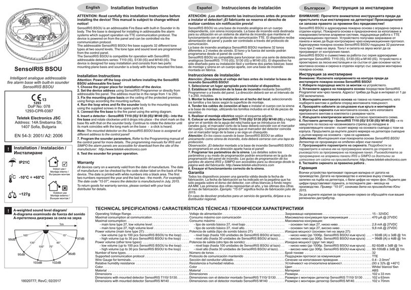
Teletek electronics SensoIRIS BSOU IS User manual

Teletek electronics

Teletek electronics SensoIRIS BSOU IS User manual

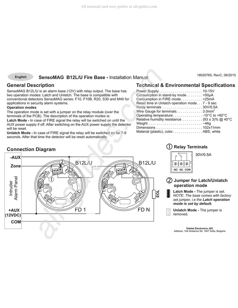
Teletek electronics SensoMAG B12L/U User manual

Teletek electronics

Teletek electronics SensoMAG B12L/U User manual

Teletek electronics Natron MCP User manual

Teletek electronics

Teletek electronics Natron MCP User manual

Teletek electronics SensoIRIS WSST User manual

Teletek electronics

Teletek electronics SensoIRIS WSST User manual

Teletek electronics IRIS Assembly instructions

Teletek electronics

Teletek electronics IRIS Assembly instructions

Teletek electronics SensoIRIS T110 IS User manual

Teletek electronics

Teletek electronics SensoIRIS T110 IS User manual

Teletek electronics SensoIRIS BSOU User manual

Teletek electronics

Teletek electronics SensoIRIS BSOU User manual

Teletek electronics SF300 User manual

Teletek electronics

Teletek electronics SF300 User manual

Teletek electronics TTE Combo User manual

Teletek electronics

Teletek electronics TTE Combo User manual

Teletek electronics SIMPO Installation guide

Teletek electronics

Teletek electronics SIMPO Installation guide

Teletek electronics SensoIRIS BSOU User manual

Teletek electronics

Teletek electronics SensoIRIS BSOU User manual

Teletek electronics SensoMAG MRB50 User manual

Teletek electronics

Teletek electronics SensoMAG MRB50 User manual

Teletek electronics iRIS8 Owner's manual

Teletek electronics

Teletek electronics iRIS8 Owner's manual

Teletek electronics SensoIRIS T110 IS User manual

Teletek electronics

Teletek electronics SensoIRIS T110 IS User manual

Teletek electronics SensoMAG F10 User manual

Teletek electronics

Teletek electronics SensoMAG F10 User manual

Teletek electronics SF50 User manual

Teletek electronics

Teletek electronics SF50 User manual

Teletek electronics SensoIRIS WSOU User manual

Teletek electronics

Teletek electronics SensoIRIS WSOU User manual

Teletek electronics SensoMAG F10 User manual

Teletek electronics

Teletek electronics SensoMAG F10 User manual

Teletek electronics Natron WSS User manual

Teletek electronics

Teletek electronics Natron WSS User manual

Teletek electronics SensoMAG F10B User manual

Teletek electronics

Teletek electronics SensoMAG F10B User manual

Popular Fire Alarm manuals by other brands

Simplex 4010ES Quick reference guide

Simplex

Simplex 4010ES Quick reference guide

Global Fire Equipment VALKYRIE AS manual

Global Fire Equipment

Global Fire Equipment VALKYRIE AS manual

Zeta Alarm Systems INFINITY ID2 installation manual

Zeta Alarm Systems

Zeta Alarm Systems INFINITY ID2 installation manual

System Sensor 22051TLE-RF-26 Installation and maintenance instructions

System Sensor

System Sensor 22051TLE-RF-26 Installation and maintenance instructions

Pittway Notifier AM2020 troubleshooting guide

Pittway

Pittway Notifier AM2020 troubleshooting guide

Ampac ZoneSense user manual

Ampac

Ampac ZoneSense user manual

Kidde VM-1 Technical reference manual

Kidde

Kidde VM-1 Technical reference manual

LST SIM016-3 Specification sheet

LST

LST SIM016-3 Specification sheet

Fireboy- Xintex FBD-MZ Owner's Manual & Installation Instructions

Fireboy- Xintex

Fireboy- Xintex FBD-MZ Owner's Manual & Installation Instructions

GST DI-9204 Installation

GST

GST DI-9204 Installation

Fire-Lite Alarms MS-2 instructions

Fire-Lite Alarms

Fire-Lite Alarms MS-2 instructions

hyfire HY5000 Series install guide

hyfire

hyfire HY5000 Series install guide

Radionics Radionics 9124 user guide

Radionics

Radionics Radionics 9124 user guide

UniPOS FD 7120 instruction manual

UniPOS

UniPOS FD 7120 instruction manual

bolid S2000-IP-03 instruction manual

bolid

bolid S2000-IP-03 instruction manual

FIREGUARD GLOBAL FG-S01_AP quick start guide

FIREGUARD GLOBAL

FIREGUARD GLOBAL FG-S01_AP quick start guide

Panasonic MEW01091 operating instructions

Panasonic

Panasonic MEW01091 operating instructions

Notifier UZC-256 installation manual

Notifier

Notifier UZC-256 installation manual

manuals.online logo
manuals.online logoBrands
  • About & Mission
  • Contact us
  • Privacy Policy
  • Terms and Conditions

Copyright 2025 Manuals.Online. All Rights Reserved.

SensoIRIS MCP150PR
SensoIRIS MCP150PB
~257 g
Installation
!
Teletek Electronics JSC
Address: 14A Srebarna Str,
1407 Sofia, Bulgaria
EN 54-11:2001
EN 54-11:2001 / A1:2005
EN54-17:2005
EN 54-17:2005 / AC:2007
DoP No: 057
1293 19
Tested by EVPU
1293-CPR-0606 Rev.1
-10°C ÷ +60°C
(93±3)%@+40°C
2
0.5-2.5mm
Intelligent analogue addressable fire
alarm manual call point
with built-in isolator module/
Intelligenter analog adressierbarer
Handfeuermelder mit eingebautem Isolator
ATTENTION: SensoIRIS MCP150PR/PB must
be connected only to fire panels, which
support TTE communication protocol!/
ACHTUNG: SensoIRIS MCP150PR/PB ist nur
mit einem Bedienfeld verbindbar, das ein
TTE Kommunikationsprotokoll unterstützt!
Indoor Use/
Innenmontage
ISOLATOR MODULE TECHNICAL SPECIFICATIONS / TECHNISCHE PARAMETER DES ISOLATORS
Vmax . . . Max. line voltage. . . . . . . . . . . . . . . . . . . . . . . . . . . . . . . . . . Max. Spannung im Kreis. . . . . . . . . . . . . . . . . . . . . . . . . . . . . . . . . . . . . . . . . . . . . 32
Vnom ...Nom. line voltage . . . . . . . . . . . . . . . . . . . . . . . . . . . . . . . . . Auslegungsspannung im Kreis .......................................28V
Vmin . . . . Min. line voltage . . . . . . . . . . . . . . . . . . . . . . . . . . . . . . . . . . Min. Spannung im Kreis .............................................15V
Vso max .Max. voltage at which the device isolates* ..............Max. Spannung, bei der das Device den Kreis unterbricht* .................7.5V
Vso min..Min. voltage at which the device isolates* . . . . . . . . . . . . . . Min. Spannung, bei der das Device den Kreis unterbricht* ..................5.9V
Vsc max .Max. voltage at which the device reconnects** . . . . . . . . . . Max. Spannung, bei der das Device den Kreis wiederherstellt** .............6.7V
Vsc min. . Min. voltage at which the device reconnects** . . . . . . . . . . . Min. Spannung, bei der das Device den Kreis wiederherstellt** . . . . . . . . . . . . . . 5V
Ic max. . . Max. rated continuous current with the switch closed .....Max. Dauerstrom bei geschlossenem Schlüssel (ununterbrochenem Kreis) . . . . . 0.7A
Is max. . . Max. rated switching current (e.g. under short circuit) . . . . . Max. Strom der Wahlleitung (z.B. beim Kurzschluss). . . . . . . . . . . . . . . . . . . . . . . 1.8A
II max . . . Max. leakage current with the switch open (isolated state) . Strom bei Lekage beim geöffneten Schlüssel (unterbrochener Kreis) . . . . . . . . . . 16mA
Zc max ..Max. series impedance with the switch closed. . . . . . . . . . . Max. Serienimpedanz bei geschlossenem Schlüssel (ununterbrochenem Kreis) .0.12Ω@28VDC;
0.15Ω@15VDC
* Note: Switches from closed to open/ Hinweis: Schaltet vom geschlossenen zum offenen Zustand
** Note: Switches from open to closed/ Hinweis: Schaltet vom geschlossenen auf offenen Zustand
18020951; RevC; 02/2019
General Description
The addressable manual call point SensoIRIS MCP150PR/PB is
designed for application in addressable fire alarm systems, which
support TTE communication protocol. The call point has a built-in
isolator module which when used allows continuous operation of
the loop in case of short circuit and without need of using additional
isolator modules.
The call point is powered on from the fire panel and can be
controlled via the communication protocol.
Working Principle
In stand-by mode the LED is blinking on every 10 seconds showing
communication with the control panel. Note: The LED indication can
be disabled/enabled from the control panel.
To alert for fire alarm situation the user has to break the glass and
to press the button - the red LED is on.
To reset the call point back in stand-by mode you have to use the
special key to open the front cover. Replace the broken glass with
new one - see the item “Maintenance”. The call point is resetting
automatically with closing the front cover back in place - a click is
heard.
The label “Out of commission” can be used until the glass is
replaced and the call point is put back into normal operation.
Testing the Call Point Operation
From the panel menus start a test procedure for fire alarm. Open
the front cover of the call point using the key. Press the button to
initiate a fire alarm. The red LED lights on. Close the front door of
the call point to reset it - a click is heard. Reset the fire panel to
normal operation mode.
Allgemeine Beschreibung
SensoIRIS MC150PR/PB ist ein adressierbarer Handfeuermelder, der speziell auf Nutzung in
adressierbaren Brandmeldesystemen, die ein TTE Kommunikationsprotokoll unterstützen,
ausgelegt ist.
SensoIRIS MCP150PR/PB ist mit einem eingebauten Isolator ausgerüstet, der die ununterbrochene
Funktion des Kreises bei einem Kurzschluss sichert und keinen zusätzlichen Isolator verlangt.
SensoIRIS MCP150PR/PB wird vom Bedienfeld gespeist und kann über das
Kommunikationsprotokoll gesteuert werden.
Funktionsweise
Im Dienstmodus blinkt die LED-Anzeige des Melders alle 10 Sekunden bei jeder Kommunikation mit
der Zentrale. Hinweis: Die LED-Anzeige kann über die Menüs der Zentrale deaktiviert oder aktiviert
werden.
Um den Brandalarm zu betätigen, muss der Benutzer das Schutzglas brechen und auf die
Drucktaste drücken – die LED-Anzeige leuchtet rot.
Zur Zurücksetzung des Dienstmodus des Handmelders hat der Installateur zuerst den Frontdeckel
durch einen speziellen Schlüssel zu öffnen. Das zerbrochene Glas ist dann nach der unter Punkt
“Wartung” beschrieben Anleitung auszutauschen. Die Zurücksetzung des Dienstmodus des
Handmelders erfolgt automatisch mit dem Schließen des Frontdeckels – es ertönt ein
Klappgeräusch.
Empfehlung: Das Schild mit der Beschriftung “Außer Betrieb” kann an Stelle des gebrochenen
Glases bis zu seinem Austausch durch ein neues Glas und der wiederholten Inbetriebnahme des
Handmelders angebracht werden.
Überprüfen der Funktionsfähigkeit
Starten Sie ein Testverfahren über die Menüs der Zentrale. Öffnen Sie den Frontdeckel des Melders
mit dem Schlüssel. Drücken Sie die auf Taste, um den Brandalarm auszulösen. Die LED-Anzeige
des Melders leuchtet rot. Schließen Sie den Frontdeckel des Melders zu, um seine Funktion in
Dienstbetrieb zurückzusetzen – es ertönt ein Klappgeräusch. Setzten Sie die Zentrale zurück, um
sie auf normalen Betriebsmodus wieder umzuschalten.
Operating voltage . . . . . . . . . . . . . . . . . . . . . . . . . . . . . . . . . Betriebsspannung . . . . . . . . . . . . . . . . . . . . . . . . . . . . . . . 15÷32VDC
Current consumption without communication (max). . . . . . . Verbrauch im Ruhemodus, ohne Kommunikation (max.) . 125µА@27VDC
Current consumption with communication (max) . . . . . . . . . Verbrauch bei Kommunikation (max.) . . . . . . . . . . . . . . . . 160µА@27VDC
Current consumption in Fire mode . . . . . . . . . . . . . . . . . . . . Verbrauch im Feuermodus . . . . . . . . . . . . . . . . . . . . . . . . 3mA
Material (plastic) . . . . . . . . . . . . . . . . . . . . . . . . . . . . . . . . . . Material (Kunststoff) . . . . . . . . . . . . . . . . . . . . . . . . . . . . . ABS
Call point type (method of operation according EN 54-11) . . Typ des Handmelders (Funktionsweise nach EN 54-11) . B
Working element (2 parts): Arbeitsbereich (2-teilig):
- Frangible element (a break glass). . . . . . . . . . . . . . . . . - Zerbrechliches Element (zerbrechliches Glas) . . . . . non-resettable / nicht rücksetzbar
- Operating element (a button). . . . . . . . . . . . . . . . . . . . . - Bedienelement (Drucktaste). . . . . . . . . . . . . . . . . . . . resettable / rücksetzbar
Indication “Fire alarm”. . . . . . . . . . . . . . . . . . . . . . . . . . . . . . Indikation des Alarmmodus . . . . . . . . . . . . . . . . . . . . . . . . red LED / LED Indikation rot
Dimensions. . . . . . . . . . . . . . . . . . . . . . . . . . . . . . . . . . . . . . Abmessungen ..................................125x125x36mm
TECHNICAL SPECIFICATIONS / TECHNISCHE DATEN
INSTALLATION INSTRUCTIONSEN INSTALLATIONSANLEITUNGDE
Installation Instructions
1. Open the front cover with the key. Remove the
key from the key-lock and keep in safe.
2. Remove the operating element and PCB
together - use a flat screwdriver to unlock the
plastic fixtures from the supporters.
3. Run the loop wires through the cable openings
and mount the box on the place of installation.
4. Set the address of the call point using
SensoIRIS Programmer (connect the 2-pin cable
to the PROG terminal on the PCB) or directly from
fire panel. The address must be in the range from
1 to 250. Note: The unique ID number of the
device is visible on a sticker placed on the back of
the front cover.
5. Connect the loop wires to the call point
terminals - see the connection diagram.
6. Place back the operating element and PCB into
the box and lock the fixtures to the supporters.
7. Remove the label “Out of commission” from the
back of the glass.
8. Close the front cover - a click is heard.
9. Test the call point functionality.
Installationsanleitung
1. Öffnen Sie den Frontdeckel mit dem Schlüssel. Ziehen Sie den
Schlüssel aus dem Schloss heraus und legen Sie ihn zur Seite.
2. Nehmen Sie die Drucktaste mit der Platine heraus – verwenden
Sie einen kleinen platten Schraubendreher, um die
Befestigungselemente von den Abstützungen abzunehmen.
3. Ziehen Sie die Verbindungsleiter durch die Kabelöffnungen
durch und montieren Sie das Gehäuse auf dem Montageort.
4. Die Adresse des Handmelders über den SensoIRIS
Programmierer einstellen (den Kabel - 2 Pins (2-pin) - an die
PROG-Klemme der PCB-Platte anschließen) oder die Menü-
Optionen zur Adressierung der Zentrale verwenden. Die Adresse
muss in der Reichweite von 1 bis 250 einschließlich liegen.
Hinweis: Die eindeutige ID-Nummer des Devices ist auf einem
Aufkleber an der Rückseite des Frontdeckels aufgedruckt.
5. Schließen Sie das Loops an die Klemmen des Melders an -
siehe Schaltplan.
6. Legen Sie die Drucktaste und die Platine zurück und verriegeln
Sie die Befestigungselemente an den Abstützungen.
7. Nehmen Sie das Schild „Out of commission“ („Außer Betrieb“)
von der Rückseite des Glases ab.
8. Schließen Sie den Frontdeckel zu - es ertönt ein Klappgeräusch.
9. Testen Sie die Funktionsfähigkeit des Handmelders.
Ј
Ј
Connection diagram / Verbindungsschema
Attention: Power off the loop circuit before installing the call point! When you use
the integrated short circuit isolator module, connect one of the “+Loop” loop lead to the
“Izo” terminal of the call point./
Achtung: Schließen Sie die Stromversorgung des Kreises aus, bevor Sie den
Melder anschließen. Damit der eingebaute Isolator in Betrieb kommt, haben Sie den
einen Ausgang “+Loop” des Kreises mit der Klemme “Izo” zu verbinden.
1. Rotate the cover up to view the key-
lock.
2. Use the key from the kit elements to
open the front cover for maintenance or
test.
1. Drehen Sie den Deckel, um den
Zugang zum Schloss zu ermöglichen.
2. Verwenden Sie den Schlüssel aus den
zur Verfügung gestellten Ersatzteilen, um
das Wartungsgehäuse zu öffnen oder
einen Test durchzuführen.
General View / Frontansicht
L+L-
Prog
Izo
L+L-
Locked/
Verriegelt
Unlocked/
Entriegelt
3. Use a flat screw-driver to unlock the
plastic fixtures from the supporters.
4. Remove the operating element and the
PCB together.
3. Verwenden Sie einen kleinen platten
Schraubendreher, um die
Befestigungselemente von den
Abstützungen zu entriegeln.
4. Nehmen Sie die Drucktaste mit der
Platine heraus.
Elements / Elemente
5. Mounting holes.
6. Cable entry holes.
7. Additional opening for cable entry,
protected with plastic cover. Suitable for
cable gland mounting, ø17mm.
5. Montageöffnungen.
6. Kabelöffnungen.
7. Zusätzliche Öffnung zur Durchziehung
des Kabels, der mit einer Kunststoffkappe
geschützt ist. Geeignet zur Montage an
einer Verschraubung mit einem
Durchmesser von ø17mm.
View from
above/
Ansicht
von oben
Front view/
Frontansicht
Mounting / Montage
Changing a broken glass./ Austausch eines zerbrochenen Glases.
Maintenance / Wartung
Note: The presented view is showing
the back side of the front cover./
Hinweis: Die angezeigte Ansicht
ist von der Rückseite des Deckels.
-Loop
-Loop
+Loop
+Loop
L+L-
Izo
L+L-
Prog