Teletics ZipLine User manual

ELETICS
ZipLine
(& ZipLine 2)
Quickstart Installation Manual
January 21, 2010
1

2
Introduction
TheTeleticsZipLineisawirelesssystemthatallowsuptotwostandard
analog(POTS)phonelinesandanethernetLAN(internet)connectionto
bequicklyinstalledbetweentwobuildingsorlocationsupto1mile/1.6
kilometersapart.
TheZipLineisdesignedtobeeasytoinstall.Youwillneedthefollowing
tools:
‐PowerDrill/Screwdriverw/Phillipsbits
‐10mmnutdriver/wrench
‐Wirefishline
Box Contents
TheTeleticsZipLineboxcontainsthefollowing:
‐2ZipLineOutdoorRadios,LINE&PHONE
‐2poweradapters
‐2AntennaMounts
‐AccessoryKit(WhiteBox)
Cabling
EachZipLineradiocomesequippedwith30Meters/100feetof
OUTDOORRATEDcablewhichrunsfromtheZipLinetothePower/POTS
PowerInjector,whichisusuallymountedinthecustomer’stelcoroom.
Thecableisusedforthephoneconnectionsaswellaspower.YOUMAY
SHORTENTHISCABLEIFYOUWISH,BUTYOUMAYNOTLENGTHENIT.
Keepinmindthatthiscablelengthmaximumdistanceisduetothe
maximumlengthallowableforthepowerwiresinsidethiscableonly.
ThecablelengthFROMtheTeleticspowerinjectorPOTSRJ11connector
TOthetelcoline,PBXordesksetmaybeupto300feetintotalusing

unshieldedtwistedpaircat3cableforthetelephonecircuitsandcat5eor
cat6forethernet/data,orevengreaterdistanceswhenusingshielded
cables.ThisallowsforalmostanyinstallationtousetheZipLinesystem.
TherearetwoconnectionscomingoutoftheZipLine.Theprecabled
connectionhasthePOTSlinesandpower,thebottommiddle
weatherproofconnectorisforCat5edata.
EachoutdoorZipLineradioshouldbeelectricallygroundedbyuseofa
groundluginstalledononeoftheboltsusedtoholdtheZipLineonthe
polemountbracketsandruntoaproperelectricalground.Thisisnot
onlyasafetyrequirementforlightningdissipationpurposes,butalso
improvessystemradioperformance,sincetheenclosureprovidesradio
shieldingagainstunwantedradioandelectricalnoiseonthephonelines.
AssumingthattheoutletwhichtheTeleticsPowerInjectorspowersupply
isproperlyinstalledaccordingtoelectricalcodes,nofurthergrounding
pointsinthesystemisrequired.Theelectricalcircuitsforthephoneand
ethernet/dataconnectionsshouldNEVERbegrounded.Thisincludesall
connectionsinthepowerinjector.Phoneconnections“float”.
Cable Gland Assembly
InsidetheaccessoryboxthatcamewiththeZipLine,
youwillfind2blackcableglandsthatlooklikethis:
Youshouldunscrewthetwoparts.Youshould
leavethesmallrubberO‐ringwhereitis.
YouwillnoticethattheO‐ringhasaslitinit.Thisisto
allowtheethernetcabletobecompletelyassembledon
theground,priortoinstallingitontheradio.
3
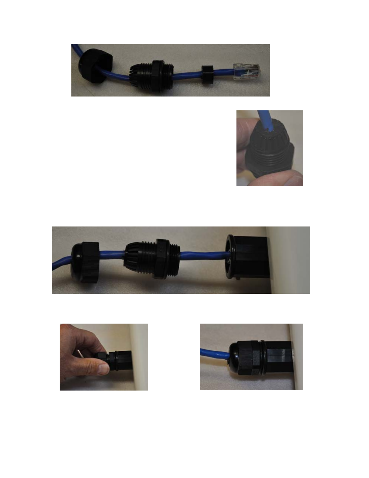
Thisistheorderthateverythinggoestogetherprioronthecable:
4
Thenextstepistopushtherubberringinto
positionsothatitwillcompresswhentheglandis
assembled.YoushouldGENTLYuseasmall
screwdrivertoslideitinsidethemainbodyofthe
glandhousinguntilitisflushwiththelittleplastic
fingersatthebottomofthegland,likeshownin
thepicturetotheright‐>
Youcannowslidetheglandupanddownthecablewhileyoupluginthe
ethernetconnectorintothebottomoftheradio:
Screwintheglandhousing: Andthenthebottomglandcap:

Installation
MounttheZipLineRadiosashighupaspossibleonbothbuildings.The
radiosmust“see”eachotherwithoutobstructionsbetweenthem,and
sinceradiotravelsina“football”shapebetweenantennas,youmustnot
onlyhaveadirectpathbetweentheantennas,butthepathalsomustbe
wideenough,asdeterminedbythedistancebetweentheradios:
Radio height required by distance between radios
Distance (mi./km) .25/.40.5/.801/1.6
Minimum Height( ft/m)
10/314/4.319/6
Forexample,ifyouhavetwobuildingsahalfmileapart,theZipLine
radiosshouldbe14feetabovetheground,plustheheightofanything
elsethatisinbetweenthebuildings.So,iftherearedeliverytrucks
movingbetweentheradios,theyneedtobe14abovetheheightofthe
trucks,soabout30feetup.Sameruleappliesfortrees,etc.
TherearetwoZipLineradiosincludedineachkit.ThereisoneLINEunit
andonePHONEunit.ThePHONEunitneedstobeconnectedtoaPhone
atthe“remote”end.TheLINEunitneedstobeconnectedtothePBX,
KeySystem,orPOTSLINEatthe“main”location.
DialtoneislocallygeneratedonthePHONEunit,soifyoureversethe
radios,youwillnotgetdialtoneatthephoneend.Thefastestwayto
checkifyouhavethecorrectradioateachendistolookatthecolorof
thecableglandontheZipLine.PHONEZipLineradioshaveBLACKcable
glandsonthetelcocable.LINEZiplineradioshaveBeigecableglandson
thetelcocable:
Beige(LINE)Radio Black(PHONE)Radio
5
Assembly Tips
Therearetwoofeverything.Herearesomebasicsetuptips:
•It REALLY matters what radio is at what end!!
•The ZipLine unit that has a BLACK cable gland on the cat3 cable
should plug into a phone or modem or fax machine. (You may
also say that this is the radio that goes to the REMOTE end, or
the end that currently does not have a phone)
•The ZipLine that has a BEIGE (or WHITE) cable gland on the cat3
cable should plug into a telephone LINE (that comes from a
phone company, or office PBX).
•You can use any other component at either end of the
installation. This includes the ZipLine Power Injectors
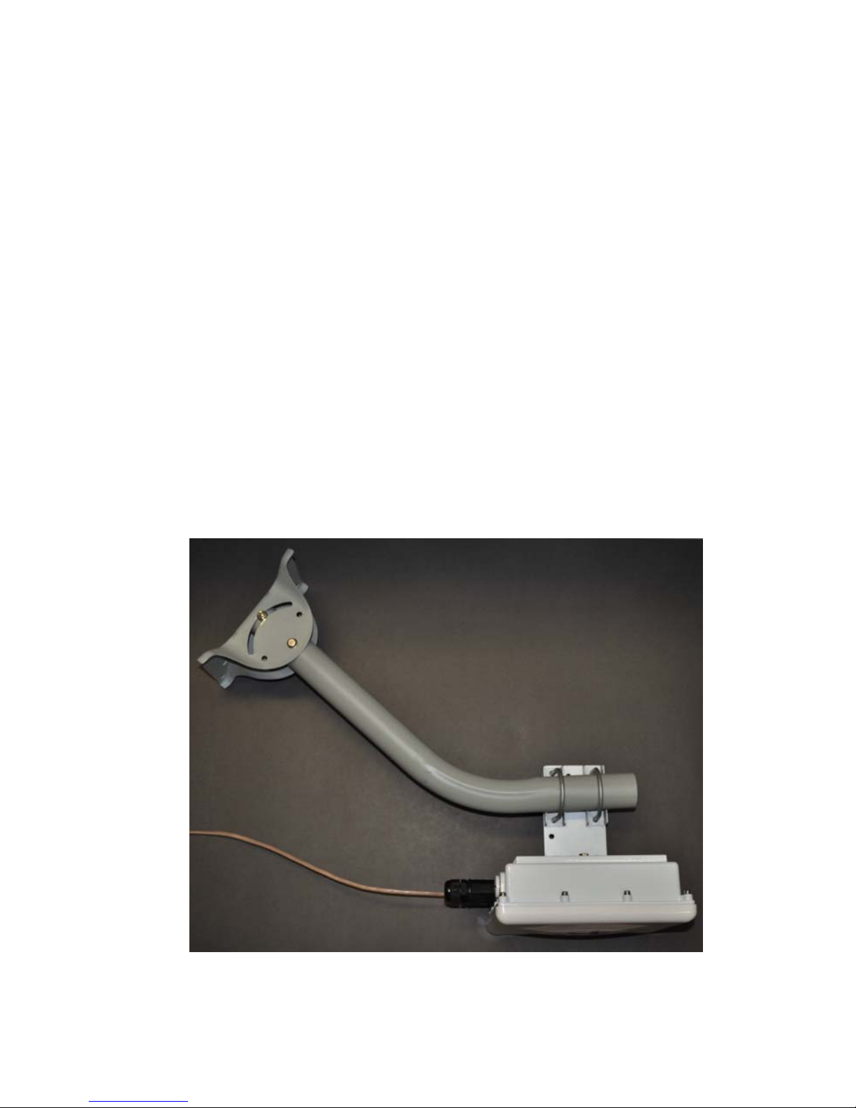
•Here is what each end will look like just before you install it:
6

•First,attachthe
aluminumbracketto
thebackoftheZipLine.
Usethe4bolts,
washers,andlock
washersthatarealready
onthebackoftheradio:
•Next, put the U-Bolts in place.
These are also packaged in the
Accessory Kit (the white box), and
are wrapped in plastic wrap, along
with washers and lock washers:
•The hardware for the
pole mounts is included
with the brackets
themselves. Look for
three bolts and 3 nuts in
brass. Here is how you
should put the pieces
together prior to
tightening anything:
7
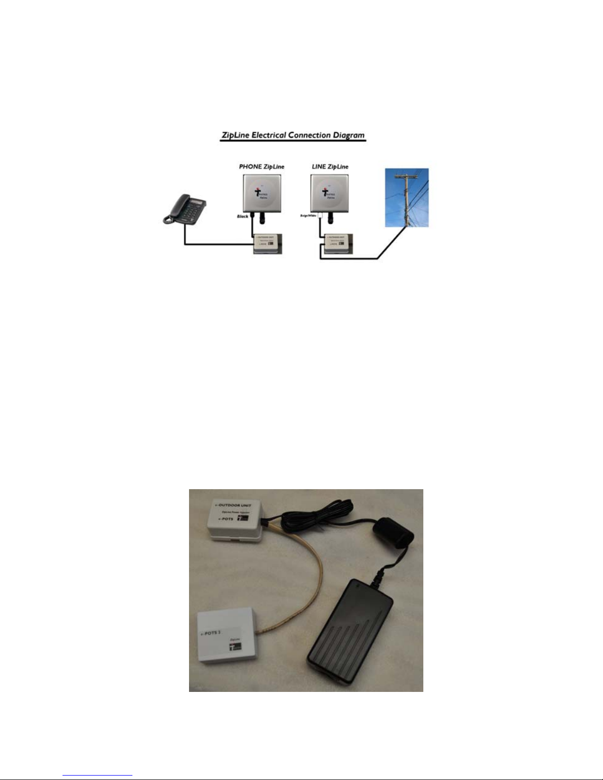
Electrical Connections
Here is a diagram of all the components in the ZipLine kit, and how they
hook together:
•The electrical connection between the power injectors and the
wall adapters have not been shown for clarity. They must be
plugged into the wall once the other connections have been
made.
•The only difference (electrically) between the ZipLine and the
ZipLine 2 is the ZipLine 2 had connections to extend a second
line over the radio link. The ZipLine 2 has a second “dongle” that
is connected to the Power Injector for the second POTS circuit.
In all other respects, the installation of the system is identical.
8

9
•It does not matter the order in which the radios are powered up.
•The weatherproof RJ45 connectors may be left unused, as long as
you tighten them to ensure no moisture or contaminants get
inside them.
•The RJ45 connection performance is about the same as an office
network LAN connection. It is suitable for email, internet access
etc.
•The RJ-45 connection on the LINE side may be plugged into an
office router, etc. If the PHONE RJ-45 connection is to be
shared between computers, it is recommended that it is routed
as well, to ensure LAN traffic between computers at the remote
end does not go “over the air”, thereby affecting the performance
of the wireless LAN connection by relaying unnecessary LAN
traffic.
Aiming the antennas
Onceyouhavecompletedtheinstallation,trytogetbothradiospointing
attheotherasbestasyoucan.Itisessentialthattheradiosaremounted
insuchawaythatthecablingcomesoutthebottom(towardsthe
ground).
TheZipLineantennasallowupto15degreesvariationinbetweenthe
PHONEandLINEunitsleft/rightandup/down.Youraimingdoesnothave
tobeperfecttohavethesystemwork.Youcanessentially“eyeballthem
in”andgetagood,stablesignal.
Forexample,ifyourZipLinePHONEandLINEunitsare500yards/meters
apart,andoneismounted5feethigherthantheother,andtheleft/right
angleisoutby3or4degrees,youwillstillhaveagoodstablelink.

TheTeleticswebsitehassoftwarethatcanassistyouingettingthebest
signalpossible.ThesoftwareiscalledTUtilZipLine24,andcanbe
obtainedatwww.teletics.com/support.Thereisnochargeforthis
software.
Startup / Testing
Once the antennas have been aligned, you may test the system by dialing
in and out of the phone at the remote end. You do not need to do
anything different than you would for any other phone that is on the
system, with one exception. If your phone system requires you to dial
“9” for an outside line, you need to dial the entire phone number with
the leading 9 at one time, ie. 919165551212, instead of “9” (Wait for dial
tone), then the number. This is called one stage dialing, and is the only
method used with the ZipLine.
If you are using the RJ45 data connection as well, you should be able to
use your computer in exactly the same way you would at the other end.
System Diagram
10

11
Basic Troubleshooting
•If you do not get a dial tone when you pick up the phone, it
is most likely that you either have no power to the PHONE
ZipLine radio, or have accidentally installed the LINE unit at
the remote end. Check that the phone is plug into a
ZipLine unit with two black cable glands (one small and one
large), and that the power adapters LED is illuminating when
power is applied.
•If you are experiencing any kind of AC hum or noise during
a phone call, this usually indicates that one of the outdoor
units has not been properly grounded. You need to ground
the outside chassis of the outdoor units in order to ensure
a suitable path to ground, both in the case of a lightning
strike, and to reduce spurious radio noise.
•Incoming ring forwarding delay is what happens to capture
caller ID on incoming calls. If you dial into the remote site
while you are right next to it, you will notice about two
rings occur before the remote site phone will ring. This is
required by the ZipLine to capture the caller ID
information, which is supplied after the first ring by the
phone company, prior to completing the call to the remote
site’s phone. This is normal.
•Grounding – The ZipLine is considered to be a low voltage
device, and therefore usually may be installed by anyone
without need for permits or inspections. However, you
need to make certain the outside case is grounded for
lightning reasons, and you should consult your local
electrical / safety codes in your area prior to performing any
kind of permanent equipment installation. Additionally, the
ZipLine Power Injector lid can be removed if you want to

12
either permanently screw it to the communications room
wall, or directly run telephone wire to the unit. However,
DO NOT GROUND ANY CONNECTIONS INSIDE THE
ZipLine POWER INJECTOR. The green wire inside the
ZipLine Power Injector is a floating phone signal – the
system will malfunction if you ground it!
•Use with Modems – The ZipLine has been tested up to
14.4kbps using standard modems and phone lines. In many
cases, higher data rates can be obtained, due to
compression that is automatically provided by the modem
protocol. To improve dial up connection times and
reliability, you should set the maximum connect speed for a
ZipLine connected remote site to 14.4 Kbps. This is
typically by setting register S37 using the ATS37=10 and
AT&N8 commands to set maximum data rates. These
commands may vary by your particular modem
manufacturer.
Technical Support
Supportcanbeobtainedbycallingyourlocaldealerorat
www.teletics.com/support
This manual suits for next models
1
Table of contents
Popular Extender manuals by other brands


Rose electronics
Rose electronics CrystalLink CLK-1U4TP-100M/PE Installation and operation manual

Intelix
Intelix DIGI-USB2-4P installation guide

Wodaplug
Wodaplug EOC Master manual

Leviton
Leviton PE200-1 installation instructions

Daikin
Daikin ROTEX EHS/500/1 quick start guide

Positron
Positron BRX-XLR user guide