IEEE 802.11a
4.9GHz
TT 4900
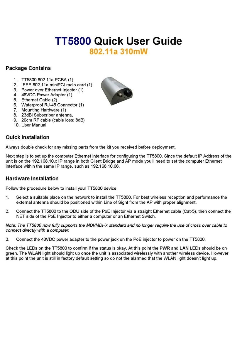
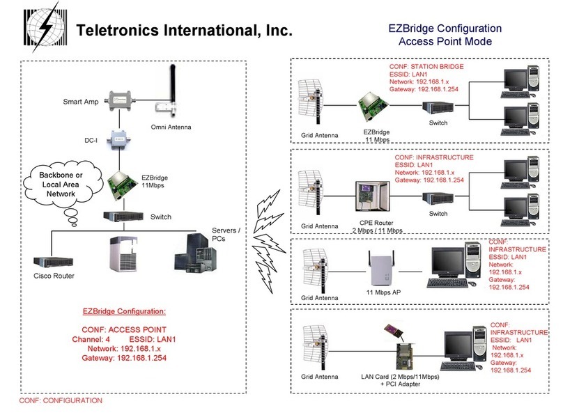
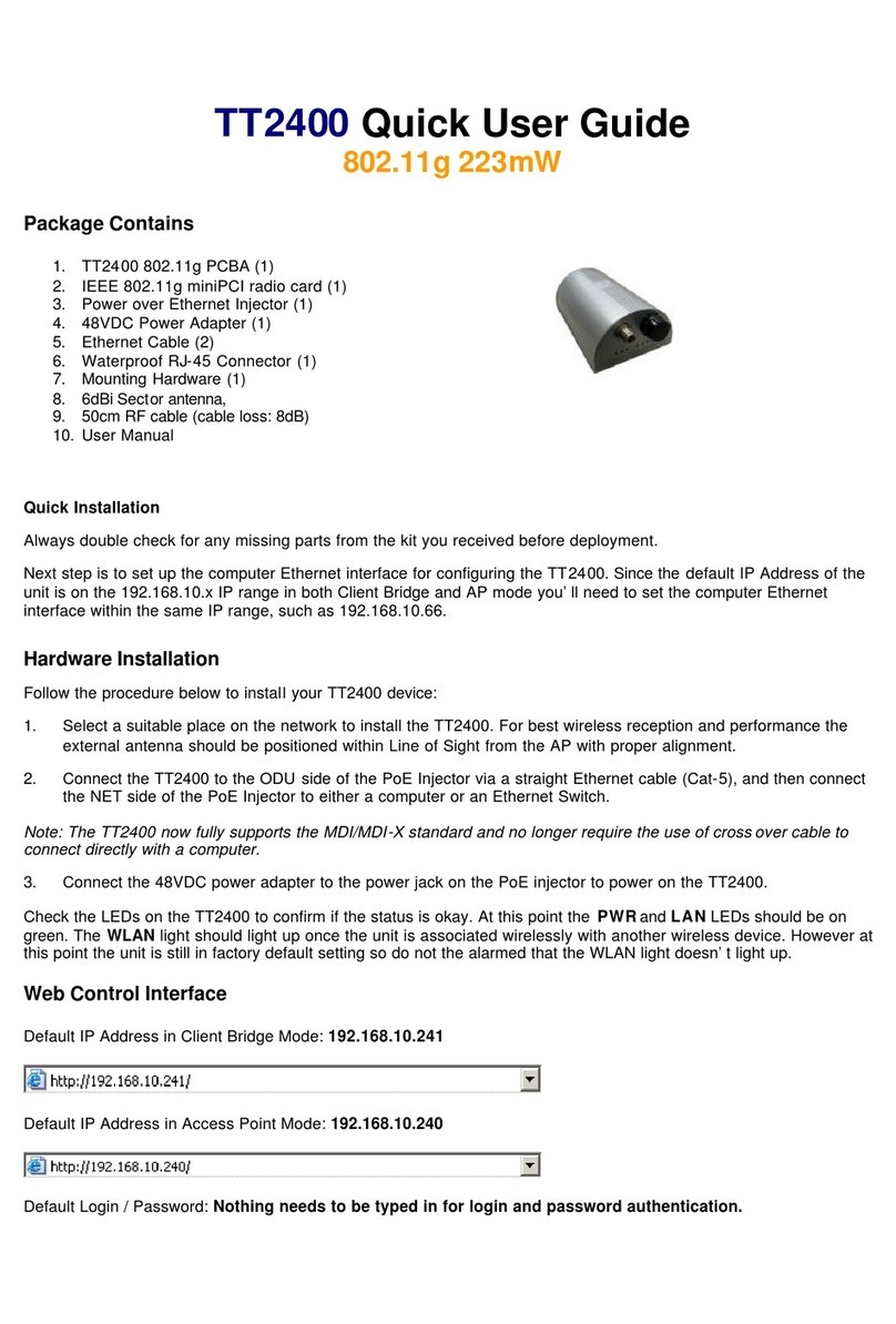
TT™4900 802.11a PCBA (1)
IEEE 802.11a Mini PCI Card (1)
Power Over Ethernet Injector (1)
48VDC Power Adapter (1)
Ethernet Cable (2)
Waterproof RJ-45 Connector (1)
Mounting Hardware (1)
Quick User Guide
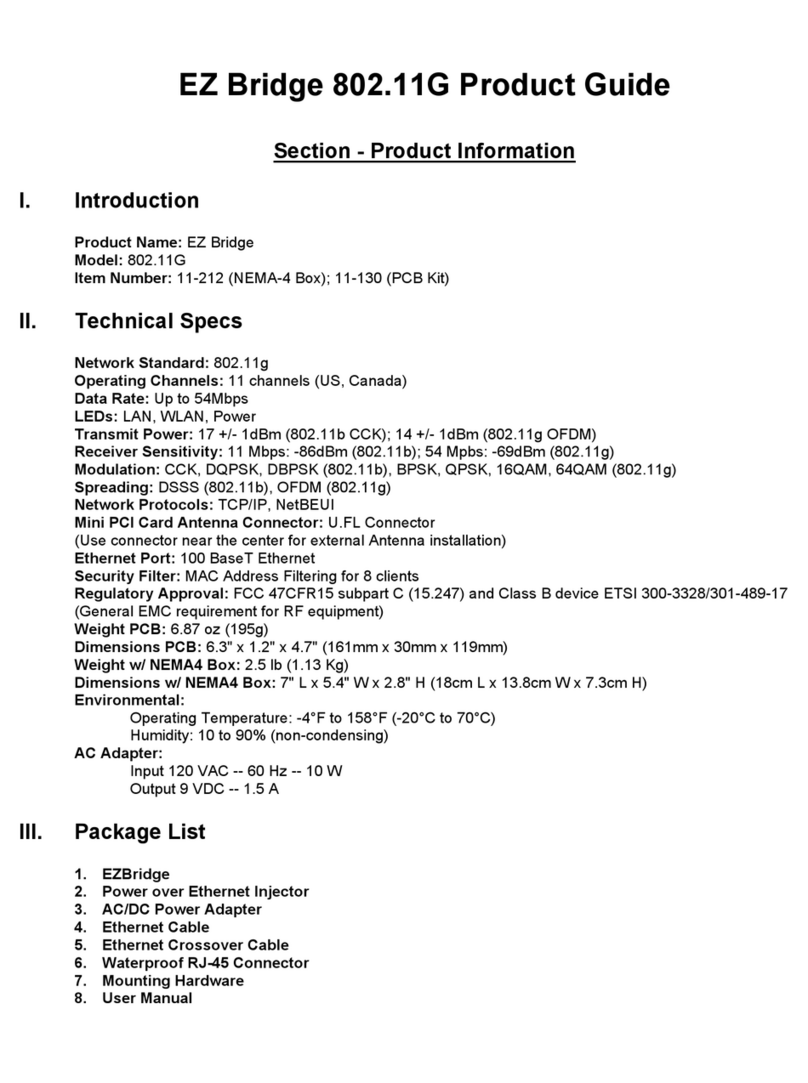
Quick Product Guide
Product Specifications:
CPU: Ubicom IP3023
Radio: Atheros 802.11a
Mechanical Specifications:
Chassis Dimension (W x D x L): 200mm x 70mm x 120mm
Board Specifications:
Network Standard: IEEE 802.11a, IEEE 802.3, IEEE802.3x
Ethernet: 10/100BaseT Ethernet, Auto MDI/MDI-X
Network Architecture Infrastructure: Ad-Hoc, MAC, CSMA/CA
Status Indicators: Power, Wireless LAN, Ethernet LAN, and RSSI
Push Button: Reset to Default Button
Radio Specifications:
(200mW)
IEEE 802.11a 5GHz Mini PCI Card
Specification Description: Chipset MAC/BB
Processor Atheros AR5213 RF Chip Atheros AR5414A
Power Consumption: Tx: ~1000mA Rx: ~400mA
Antenna Connector: N-type Female
Output Power:
Receiver Sensitivity: -90 dBm @ 6 Mbps
-72 dBm @ 54 Mbps
RF Channels: Total of 12 Non-Overlapping Channels
(4 Channels: 5.725 ~ 5.850 GHz)
Data Security: WPA/WPA2, 64/128 bit WEP
Fully Transparent Bridge: Unlimited MACs
Management: Web and SNMP based Management
DC Power Input: Includes 48VDC Adapter and PoE
Injector with surge protection, IEEE 802.3af compliant
Frequency Band: 4.950, 4.960, 4.970 GHz
Operating Environment: -40 °C to + 70 °C
Enclosure: Silver Powder Coated Cast Aluminum
23 dBm (+/- 1.5dB) @ 6/9/12/18/24 Mbps
22 dBm @ 36 Mbps
21 dBm @ 48 Mbps
18 dBm @ 54 Mbps
TT™4900 FEATURES
1.
2.
3.
4.
5.
6.
7.
8.
Package List
Ultra High 500mW Output
power in OFDM modulation
(w/optional M58 Amplifier)
Web & SNMP based Management
Transparent bridging supports
unlimited MACs
WPA/WPA2 & 64/128 bit WEP
Data Security
5 Ultra-bright LEDs indicating RSSI
Ruggedized Waterproof &
All-Weather Enclosure
7.87" x 2.75" x 4.7"
Warranty Policy
Limited Warranty
1. All Teletronics products have 1 Year Warranty Period. (Except List of Antennas Attached)
2. Our Warranty Period does not cover physical damages, misuse of the product, and natural disasters.
3. International customers have 60 business days return policy, in order to receive full refund for the
items purchased. Only if the item is consider to be brand new unit. (Unopened Items)
4. Domestic customers have 30 business days return policy, in order to receive full refund for the items
purchased. Only if the item is consider to be brand new unit. (Unopened Items)
5. Within the 30/60 business days, for all used items, there will be a restocking fee charge (0-45%).
Depending on the condition of the item. Restocking Fee might vary.
6. All original materials must be returned in good resalable condition.
7. No refund, exchange or full credit will be issued after the 30/60 business day return policy.
8. Out-of Warranty items are repaired or replaced only with the customer’s prior approval. Labor charges
and freight will vary based on the condition of defective item.
9. Advanced Replacement Cases, must be issued within the 1 Year Warranty Period
10. All RMA numbers automatically expire 30 days after date of issuance.
11. Teletronics reserves the right to refuse any RMA shipment that does not come with RMA Case
Number or an invalid RMA Case Number.
Terms & Conditions
1. REPAIR WARRANTY: All warranties are void if Teletronics finds that the product has been abused, physically damaged
or altered in any way without prior written authorization. 2. OUT OF WARRANTY PRODUCT: Out-of-Warranty Products are
repaired only with the customer’s prior approval. For Out-of-Warranty repair charges, please contact us at 301.309.8500
x136
or
[email protected].
3. PACKAGING: Please clearly mark the RMA number on the outside of the packaging. Damage or loss of goods during shipment is the sole responsibility of the customer. Product must be returned in original
carton or in packaging of equal or greater quality. 4. RMA NUMBER: Any returned product without a valid RMA number or
no RMA number will be refused and returned to the sender. RMA numbers are only valid for 30 days from the date they
are issued. Please write the RMA number on the box in bold letters using permanent marker on at least two different sides
of the box. 5. PRODUCT: Ship only the product(s) specified on the original RMA request and includes any additional
items. Any additional products will require a new RMA number. 6. SHIPPING COST: The customer is responsible for the
cost of shipment to Teletronics and we will be responsible for the cost of shipment back to the customer. Ship to:
Teletronics International, Inc. 2 Choke Cherry Road, Suite 100 Rockville, MD 20850 USA. 7. SHIPPING METHOD: All the
repaired products will be shipping back to customers via UPS/FedEX Ground service. For International customers via
Economic 8. ADVANCED REPLACEMENT: If you are requesting Advanced Replacement for the defective product, you must
provide us with a valid credit card number as a guarantee. Please Note: Advanced Replacement charges will be applied to
the customer’s credit card, if the defective product is not received by Teletronics within 21 business days.
9. RMA REFUND: Customer is required to provide the original invoice/receipt to request RMA credit.
6 Easy Steps to Receive an RMA Case#
1. Go to: http://www.teletronics.com/RMA.html
2. Download the RMA Form; fill it out the entire fields with the appropriate product information
4. Within 1 Business Day, you will receive an email with the RMA Receipt Confirmation
5. Package the defective unit with the suitable material
6. Identify the outside of the box with the RMA Case # given in the RMA Receipt
7. Ship the package to: Teletronics – RMA Dept 2 Choke Cherry Rd, Suite 100. Rockville, MD – 20850 USA
NOTE: Advanced Replacement Cases must be issued before 4:30pm (Eastern Time),
in order to ship the package the same business day.
*Specifications Subject to Change without Prior Notice!
All Rights Reserved. Copyright 2006 Teletronics International, Inc.
2 Choke Cherry Road, Rockville, MD 20850 Tel: 301.309.8500 Fax: 301.309.8851
