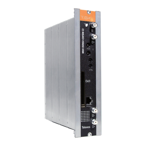
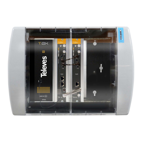
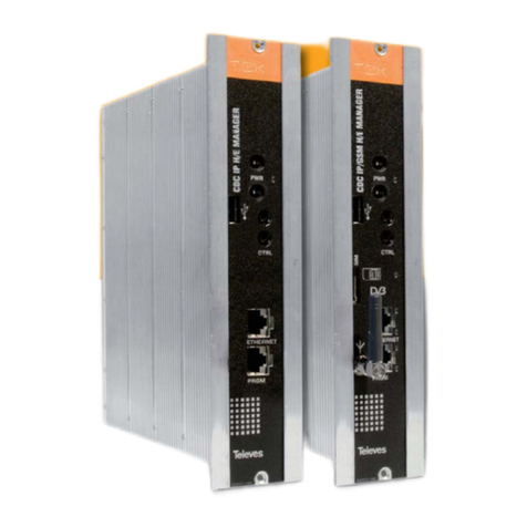
Televes TOX Series User manual

DVBS2 - QAM CI
EN
Ref. 563501
User Instructions
www.televes.com


ENGLISH
EN
Contents
1. Technical specifications ...................................................................................................................... 5
2. References’ descriptions .................................................................................................................... 7
3. Mounting ............................................................................................................................................. 8
3.1. Wall mounting .............................................................................................................................. 8
3.2. 19” rack mounting ...................................................................................................................... 9
4. Elements’ descriptions ....................................................................................................................... 10
4.1. DVBS2-QAM CI ......................................................................................................................... 10
4.2. Power supply unit ..................................................................................................................... 11
4.3. Amplification options .............................................................................................................. 12
4.4. Universal programmer ............................................................................................................. 13
5. How to use the product ...................................................................................................................... 14
5.1. Standard Menu ........................................................................................................................ 14
5.2. Extended menu ......................................................................................................................... 16
5.3. Saving of parameters ............................................................................................................... 18
6. Controlling the device ........................................................................................................................ 19
7. Example of application. Distribution of 7 DVB S2 channel in QAM format ........................................ 20
8. Rackmount standards ........................................................................................................................ 21
9. Standards for mounting cabinets ....................................................................................................... 23
DVBS2 - QAM CI


EN
5
1. Technical specifications
* The unit’s consumption with CAM will depend on the type of CAM being used. For the LNB it is considered a standard consumption of 250mA.
The Power Supply Unit is able to powering up to seven DVBS2-QAM CI modules maximum.
Is necessary to use both PSU outputs when consumption of one of them exceeds 4A (maximum current in each output).
The technical characteristics described are dened for a maximum ambient temperature of 45°C (113ºF). Forced ventilation must be used for higher temperatures.
Satellite
Demodulator
Input Frequency MHz 950 - 2150 Through losses (typ.) dB < 1.5
Symbol rate 7.5 Mbaud 10 -30 Modulation DVB-S2 QPSK, 8PSK
DVB-S 2 - 42.5 DVB-S QPSK
Frequency Steps MHz 1 FEC Inner code LDPC 9/10, 8/9, 5/6, 4/5, 3/4, 2/3, 3/5, 1/2, 1/4,
1/3, 2/5
Input and Output
connectors type “F”female FEC Outer code Bose-Chaudhuri-Hocquenghem
Input impedance ohm 75 Roll-o Factor % 20, 25, 35
LNB power&tone control Vdc/KHz 13-17- OFF / 22KHz (ON-OFF) Return losses (min.) dB 10
QAM
Modulator
Modulation format QAM 16, 32, 64, 128, 256 Scrambling DVB ET300429
Symbol Rate max. Mbaud 6,9 Interleaving DVB ET300429
Roll-o Factor % 15 Bandwidth (max.) MHz 8.3
Block Code Reed Solomon (188, 204) Spectral inversion (selec.) Normal / Inverted
RF output
Output Frequency (selec.) MHz 46 - 862 Through losses (typ.) dB < 1,5
Frequency steps KHz 250 Return losses (typ.) dB > 12
Output level (max.) (selec.) dBμV 80 ±5 Input and Output
connectors type “F” female.
Output level adjustment
(progr.) dB > 15 Output Impedance ohm 75
General
Consumption 24Vdc
(with signal)* mA
300 (no CAM inserted; LNB power OFF)
400 (CAM inserted; LNB power OFF)
550 (no CAM inserted; LNB power ON)
650 (CAM inserted; LNB power ON)
Protection index IP20

DVBS2 - QAM CI 6
1.2. Broaband Amplifiers technical specifications
1.3. Power Supply Unit technical specifications
Power Supply Unit
5629
Mains voltage Vac/Hz 196 - 264 / 50-60 Total current (max)
(outpur 1 + output 2) A5
Output voltage Vdc 24 Max current per output A 4
Amplier
5575
Frequency range MHz 46 ... 862 Connector type “F”
Gain dB 44 ± 2,5 Powering voltage Vdc 24
Regulation margin dB 20 Consumption at 24 Vdc mA 450
Output level (60 dB)
42 CH CENELEC dBμV 105 Test socket dB -30
Amplier
451202
Frequency range (1) MHz 47 ... 862 Connector type “F”
Gain (1) dB 40 - 53 (selectable) Mains voltage Vac/Hz 196 - 264 / 50-60
Max. output level (1)
DIN 45004B dBμV 129 Max. Power W 16
Frequency range (2) MHz 5 ... 30 Test socket dB -20
Gain typ. (2) dB 20/ -3
Maximum output level (2)
DIN 45004B dBμV 129/ ---
(1) Forward channel (2) Return channel (active/passive)
1.4. Blocks Diagram
Demodulator
DVB-S
DVB-S2
TS Process
Modulator
QAM
INPUT
SAT Interface
CI
CAM
Up
Converter OUTPUT
DVB-C

EN
7
2. Description of references
Product Range
563501 DVBS2-QAM CI T-0X
5575 T.0X Broadband Amplier 44dB 120dBμV
451202 Amplier DTKom (47 - 862 MHz)
5559 T.0X Headend Manager CDC-IP
555901 T.0X Headend Manager CDC-IP GSM
5629 T.0X Power Supply Unit 24VDC/5A
Accessories
7234 Universal Programmer
5071 T03-T05-T.0X Wall mounting rail L=50 cm
5239 T03-T05-T.0X Wall mounting rail (12 Modules+PSU) L=56 cm
5301 19” Subrack frame
507202 T.0X Lockable cabinet with Ventilation Unit (7 Modules + PSU)
4061 75 Ohm DC-Block terminal load
4058 75 Ohm terminal load
422601 T05 to T.0X Power interconnection lead L=40 cm
422602 T05 to T.0X Management interconnection lead L=40 cm
422603 T.0X Management interconnection lead L=1m
5673 Blank plate

DVBS2 - QAM CI 8
UQQA-S2-CI-S
DVBS 2-QAM CI
UQQA-S2-CI-S
DVBS 2-QAM CI
UQQA-S2-CI-S
DVBS 2-QAM CI
UQQA-S2-CI-S
DVBS 2-QAM CI
UQQA-S2-CI-S
DVBS 2-QAM CI
UQQA-S2-CI-S
DVBS 2-QAM CI
ABC
BROADBAND AMPLIFIER
TEST
(-30dB)
1
2
CLAC!
7234
5575
4061
5071
5239
563501
5629 IF SAT
input
QAM
output
3. Mounting
3.1. Wall mounting
NOTE: The use of both PSU power outputs is recommended to balance the consumption. For example, 4+3 or 3+4

EN
9
UQQA-S2-CI-S
DVBS 2-QAM CI
UQQA-S2-CI-S
DVBS 2-QAM CI
UQQA-S2-CI-S
DVBS 2-QAM CI
UQQA-S2-CI-S
DVBS 2-QAM CI
UQQA-S2-CI-S
DVBS 2-QAM CI
UQQA-S2-CI-S
DVBS 2-QAM CI
BROADBAND AMPLIFIER
PWR
TEST
(-30dB)
5301
3.2. 19” rack mounting

DVBS2 - QAM CI 10
(UHF or VHF and with a maximum bandwidth of 8
MHz) using an agile up-converter.
Additionally, it incorporates a Common Interface
slot for inserting a conditional access module
(CAM) that permits the unscrambling of services.
Programming of the transmodulator operating
The DVBS2 to QAM transmodulator with CI receives
a satellite transponder, in any of DVBS (QPSK) or
DVBS2 (QPSK or 8PSK) modulation formats, and
demodulates it to obtain a transport stream packet.
Then, the transport stream packet is modulated in
QAM format and converted to the output channel
parameters (input frequency, output channel,
modulation format and adaptation of services
mainly) is performed by means of the universal
programmer (ref. 7234).
4. Elements’ descriptions
4.1. DVBS2 - QAM CI
1
3
2
4
CAM
UQQA-S2-CI-S
CTRL
PRGM
DVBS2-QAM CI
PWR
6
7
9
5
8
1. SAT IF input
2. SAT IF output
3. RF input
4. RF output
5. Powering input
6. Status LED
7. Control BUS connector
8. CAM slot
9. PC/Programmer socket
Insert the smartcard completely
into the CAM slot before powering
modules. Card contacts looking
left and forwards when it is being
inserted.
02340036001 003
CTRL
CAM PRGM
B

EN
11
4.2. Power supply unit
Connectors to
power the
modules (1)
Status LED
(1)
Mains input
230V~
02340039001 003
UQQA-S2-CI-S
CTRL
DVBS2-QAM CI
PWR
REMARK: - The Power Supply Unit is able to powering up to seven DVBS2-QAM CI modules maximum.
- Whenever the demand of power exceeds 4A (max. current for each output), it is necessary to distribute it between the two powering outputs of the PSU.
24V: OK
0V: Overload or short circuit
24
24
24
0
0
24
Masa

DVBS2 - QAM CI 12
1. RF output
2. Test output
3. RF input 1
4. RF input 2
5. Powering input
6. Status LED
7. Attenuator
1. Mains input (196- 64 V~ 50/60 Hz)
2. Ground terminal
3. ON/OFF LED
4. MATV input / Return channel output
5. MATV input test
6. MATV output test
7. MATV output / Return channel input
Broadband amplier (47 a 862 MHz.) in shielded zamak
chassis, with gain congured by the installer.
It features two input connectors, to allow mixing of channels coming out from
two different systems. If only one of the inputs is used, it is recommended to
load the unused input with a 75 ohm terminator, ref 4061.
As the rest of T.0X units, this amplier is powered via the 24 Vdc power BUS.
Input signals through connectors 3 & 4 are combined and amplied in the
frequency band 47-862 MHz
4.3. Amplication options
OPTION “A” - Amplier ref. 5575 OPTION “B” - Amplier ref. 451202
1
3
2
4
5
6
7
02340038001 002
BROADBAND AMPLIFIER
PWR
TEST
(-30dB)
I. max 150mA
196-264 ~ 50/60Hz
Fuse: T1A L 250
USO EXCLUSI O EN INTERIOR
FOR INDOOR USE ONLY
¡¡¡ATENCIÓN!!!
NO ABRIR. TENSIONES ELE ADAS DENTRO
¡¡¡WARNING!!!
DO NOT OPEN. LIVE PARTS INSIDE
Test IN
-20 dB
MATV
10 dB 10 dB
C. Ret
OK - Return
OK - MATV
20 dB20 dB
Test OUT
-20 dB MATV
+10 dB
C. Ret
On
Ret.
IN
Ret.
OUT
MATV 20 dB
02340019002
1 2 3 4 5 6 7

EN
13
4.4. Universal Programmer PCT 5.0
ABC
PCT 4.0 UNIVERSAL
The programmer features 4 buttons:
(short press) - Selection of parameter
(positioning of the cursor).
-Modication of the parameter chosen by
the cursor (ashing)
(short press) - Change menu
(long press) - Change between Principal
and Extended menus
(long press) - Save changes to memory
+ Cloning menu.
+ + Increases the contrast of the screen.
+ + Decreases the contrast of the screen.

DVBS2 - QAM CI 14
5.1. Standard Menu
a. Input menu
The rst main menu allows selection of input
frequency, the symbol rate, and the LNB
powering (0, 13 V-22KHz, 13 V, 17 V-22KHz, 17 V)
INPUT
Freq:1922MHz
27.500 Kbaud
LNB:1 V22KHz
To modify the frequency, press until the cursor
shifts over the desired digit. Then change its value
using keys and .
The range of allowed input frequency values is
950-2150 MHz, whereas the range for symbol rate
is 10 to 30 Mbaud for DVB-S2 signals and 2 to 42.5
Mbaud for DVB-S signals.
In the event that there is a “short circuit” in the
input connector (LNB powering enabled), the
LED will ash on the front of the module until the
condition disappears.
5. - How to use the product
Connect the controller to the front socket of the
module (“PRGM”).
At rst, the controller’s rmware version will
appear:
PCT firmware
version
------------
V:5.
Next, it is displayed the rmware version of the
DVBS2-QAM CI module :
Unit
Firmware
version:
1.00.00016
b. QAM Modulation menu
The following standard menu displays the
selectable QAM modulation output parameters:
QAM
Mod: 256QAM
IQ: normal
Baud:6.900Mb
The available options for this menu as well as their
possible values are:
• QAM modulation order: 16QAM, 32QAM,
64QAM, 128QAM and 256QAM.
• The IQ parameter is the modulation format
selection and can be set to “normal” or
“inversion”.
• In the processing mode (see Versions menu)
the user must select the baud rate of the QAM
output, up to a maximum of 6.9 Mbaud.
In transparent mode, this parameter is
calculated automatically as a function of
both input rate and modulation order you
have selected, and can not be changed. If the
selected QAM modulation is not able to make
room to the input rate, it will show “OVF!”
(Overow) and the value of the QAM output
rate. If the satellite input is not engaged, it
will show “Baud: unlock”.
Remark: The bandwidth required depends on the
number of services present on the output
(those selected as ON or DCY, see menu
of services).

EN
15
c. Output menu
The next standard menu shows the frequency
or output channel, the level control and the
selection of output spectrum inversion.
OUTPUT
Ch:C21
(474.000MHz)
Lev:99 Norm.
OUTPUT
Freq: 474.00
Level: 99
Output:Norm.
To change a parametre, press key until the
desired parametre starts ashing. Then you can
change its value by means of keys and .
The output frequency range is 46 to 862 MHz
The output level control allows values between 00
and 99.
The available output values are:
• Norm Normal Output Mode
• CW Continuous Wave Mode. A continuous
carrier is generated in the output
frequency selected (useful for balancing
the headend in the absence of an input
signal).
• OFF No output is generated.
• NULL QAM output modulation with null
packets only
d. Services menu
This menu shows the list of transport stream
services selected. Each time the user selects a new
input transport stream, the unit performs a search
for services.
During the process, the unit will show the message
below displaying the number of channels as soon
as they are being found:
SERVICE
Scanning: 1
Once the search has completed, a list of services is
displayed with the following information:
SERV 10125
2/8 18/25
France 2
OFF
It is indicated the service order number as well
as the total number of services in the multiplex
(the gure indicates that the 2nd service out of
8 services, is available), the statistics (18/25) and
the service name. In the processing mode (see
Versions menu) it is shown if the user has selected
it to: either remove its encryption from the output
(OFF) by means of a module CAM (DCY), or to pass
through without modication (ON).
Statistics information is the following: rst number
indicates the percentage of the output occupied
by the displayed service; second number indicates
the free percentage at the output.
In the example:
• Service “La2” would occupy the 18% of the
output (since it is set OFF, means that it is being
eliminated)
• There is a 25% of free room.
• So we can easily see that, in principle, this
service could be activated (ON or DCY), since
there is still sucient capacity at the output.
The free capacity percentage at the output is
only updated once recorded the conguration
of services.
Additionally, on the upper right corner of the
window it is indicated the status of the service
(scrambled or plain) at the input and at the
oputput:
Service scrambled at the input and at
the output.
Service scrambled at the input and
plain at the output.
Service scrambled at the input.
If the service is set to OFF (removed) shows the
service identier (service_id) in decimal format.
In the transparent mode ((see Versions menu) it is
not possible neither eliminate nor decode services,
so no changes are allowed on this menu.

DVBS2 - QAM CI 16
e. Measurements menu 1
The next menu provides an indication of the
quality of the input signal by estimating the C/N
(dB) and the link margin (dB).
MONITOR >>
C/N:14.1dB
L.M.: 7.7dB
f. Measurements menu 2
This menu shows the occupancy rate of the
output of the module as well as the maximum
reached. Exceeding the maximum occupancy
rate will cause an overow at the output, and this
condition wil be indicated.
MONITOR
Occupancy:
76%
Max:80%
MONITOR
Overflow!!
It is not recommended occupancy values above
82%. This menu is “read only”, therefore keys and
are not operational.
You can reset the maximum occupancy by pressing
.
In the transparent mode (see Versions menu),
if the QAM modulation selected does not allow
make room for the input rate, it will be indicated
by “Overow!” as well as indicating the actual QAM
output rate.
5.2. Extended menu
When the key is held down for more than 3
seconds the unit displays a series of menus that are
used less frequently, called extended menus.
a. Conguration Menu
This menu allows to:
- Set the address of the unit (it is needed whenever
the unit has to be controlled by the Headend
Manager CDC).
- It also selects the state of servicesonce the input
scanning is nished :
SERV ON: At the end of the scan all services are
set to ON state.
SERV OFF: At the end of the scan all services are
set to OFF state.
- Either channel of the table to be used or the mode
of operation using the channel frequency.
CONFIG.
CDC Adr: 001
SERV: ON
CCIR N.Z.Ind
Tables of channels available for selection are:
• CCIR
• China
• Chile
• Italy
• France
• OIRT channels
• Irland
• South Africa
• Polond
• Australia

EN
17
b. Identifiers menu
Some DVB-C receivers may have problems
receiving transmodulated channels that share
the same identier (transport_stream_id). To avoid
these cases, the user can change the following
output multiplex identiers:
transport_stream_id (ts_id)
network_id (n_id)
original_network_id (on_id).
You can choose between Auto mode (identiers
are not changed) or Manual mode.
When switching from Auto mode to Manual mode,
the display lists the identiers received at the input
and the user can change them.
NIT IDs
Auto
IDs Manual
ts_id:0x04fc
n_id: 0x055f
on_id:0x055f
This menu is not displayed in Transparent mode.
Output tables are the same as the input ones.
c. Temperature measurement menu
The following menu indicates the unit’s current
temperature as well as the maximum recorded. It
is possible to reset the maximum by pressing the
key.
MONITOR
Now: 04
Max: 05
reset
The recommended operational margins are as
follows:
• Optimum Operation : 0-6
• High Temperature: 7-8
• Excessive Temperature: 9-10
If the maximum recorded is outside the optimum
margin, the installation should be revised in an
attempt to reduce the temperature.
If the DVBS2-QAM CI modules have been installed
in a housing ref. 5069 and the temperature of one
of the modules is outside of the optimal operating
range, the ventilation unit will have to be installed
ref. 5334. To check whether this change is e ective
the maximum can be reset and its value checked
after a given time.
d. Versions menu
This menu displays the rmware versions for
the unit as well as the one of the QAM modulaor
(FPGA).
VERSION
FW:1.00.4
Mod:1.00.9
Transparent
It also lets you select between two modes of
operation:
- Processing: delete / decode services; generate
output tables and LCNs. The user selects the baud
rate of the QAM output.
- Transparent: The input data pass to the output,
simply by changing the modulation. You can not
neither delete/decode services nor adding LCNs.
The QAM output rate is calculated from both
satellite input rate and QAM modulation order
selected.

DVBS2 - QAM CI 18
e. CAM user interface menu (MMI)
This menu allows access to the user interface
conditional access module (CAM), for example,
check versions or rights of the card:
CAM MMI
Press for
menus
f. LNC (Logical Channel Number)
menu
This menu lets you assign a LCN (Logical Channel
Number), between 1 and 1023, to the services
that are present at the output (those marked ON
or DCY).
LCN
1/4
Fashion TV
N:000
LCN
/4
Soyuz TV
NO LCN
To change the LCN, make use of keys , and ▲or
▼. If you select 0000 as the LCN, it will show “NO
LCN.”
This menu is not displayed in Transparent mode.
g. Language Menu
This last extended menu allows the selection of
menu languages (Spanish / English / German/
French):
LANGUAGE
English
By pressing the keys ▲and ▼, you change the
selected language.
5.3. Saving of parameters
Once the desired value has been selected in any
of the menus (normal or extended), in order to
save the information, hold down the key for
approximately 3 seconds. The screen will display
the following:
Saving
settings and
restarting
...
If you change the conguration data, but these
have not been recorded, the previous settings
are restored after 30 sec of elapsed time, ie, the
changes are canceled.

EN
19
6. - Controlling the Device
This version of the DVBS2-QAM CI allows
conguration and monitoring via a PC, both locally
and remotely.
a. Local control
The “Headend Management” programme (v2.14
or higher) is required, as well as a special lead
(provided with the programme) that connects a PC
serial port to the “PRGM”socket of the DVBS2-QAM
CI module.
The programme can be used to set up and read all
the operating parameters, as well as to monitor the
correct operation of the device.
b. Remote control
It is necessary to have a Headend Control module
(ref. 5559 or 555901) that includes the programme
mentioned above.
Once the communication with the headend
control has been established, all the controllable
devices that have been installed in the headend
can be accessed. In this case it is imperative that
each module is programmed with a dierent
device address selected between 1 and 254.
LANGUAGE
English
CAM MMI
Press for
menus
MONITOR
Now: 04
Max: 05
reset
CONFIG.
CDC Adr: 001
SERV: ON
CCIR N.Z.Ind
MONITOR
Occupancy:
76%
Max:80%
MONITOR >>
C/N:14.1dB
L.M.: 7.7dB
OUTPUT
Ch:C21
(474.000MHz)
Lev:99 Norm.
INPUT
Freq:1922MHz
27.500 Kbaud
LNB:1 V22KHz
Long press
Menu Structure
IDs Manual
ts_id: 0x04fc
n_id: 0x055f
on_id: 0x055f
LCN
1/4
Fashion TV
N:000
~
QAM
Mod: 256QAM
IQ: normal
Baud:6.900Mb
SERV 10125
2/8 18/25
France 2
OFF
VERSION
FW:1.00.4
Mod:1.00.9
Transparent

DVBS2 - QAM CI 20
7. Example of application
Distribution of 7 DVB S2 satellite channels in QAM format.
DVBS2-QAM CI
DVBS2-QAM CI
DVBS2-QAM CI
DVBS2-QAM CI
DVBS2-QAM CI
DVBS2-QAM CI
DVBS2-QAM CI
5629
451202
75 ohm
4061
The diagram shows the reception and processing of 7 DVB S2 channels to be distributed as QAM channels.
At any situation, the limitation of 4 A per output of the PSU must be kept in mind.
QAM Output
7 x 563501
Other manuals for TOX Series
21
This manual suits for next models
1
Table of contents
Other Televes Network Hardware manuals