TELEWAVE 44 User manual

www.SteamPoweredRadio.Com
TELEWAVE,
INC
.
Operation
Manual 7034
Revision
A,
February,
1979
j!a!~/1/ep
~/..
13/1979
611
MODEL
44
BROAD
BAND
RF
WATT
METER
DESCRIPTION
AND
OPERATION
CONTENTS
1.
GENERAL
2.
PHYSICAL
DESCRIPTION
3.
FUNCTIONAL
DESCRIPTION
4. SPECIFICATIONS
.
....
-
~TELEWAVE
J7
g
REV
•
FWD
.,
'
.OFF
so. !I
150•
soo·
..
-
Model 44
Broad
Band
RF
Watt
Meter
©
TE
L
EWAVE.
INC.,
1979
PRINTED
IN
U.S
.
A.
(1
15}
'¼t
-'f-f'd[)
PAGE
3
5
7
9
Page 1

www.SteamPoweredRadio.Com
7034
5.
6.
7.
CONTENTS
OPERATION
Unpacking
RF
Connections
Incident
Power
Measurements
Reflected
Power
Measurement
VSWR
Calculation
True
Power
At
Load
Calculation
Directivity
Error
Ins
ertion
Error
MAINTENANCE
Warranty
Service
Calibration
Replaceable
Parts
REFERENCE
•
••
I
Page 2
PAGE
10
10
10
11
11
12
13
13
13
14
14
15
17
18

www.SteamPoweredRadio.Com
7034
1.
GENERAL
1.01 This
manual
provides
the
physical
and
functional
description
and
operating
theory
necessary
for
effective
use
of
the
Telewave,
Inc.,
Model
44
Broad
Band
Radio
Frequency
(RF)
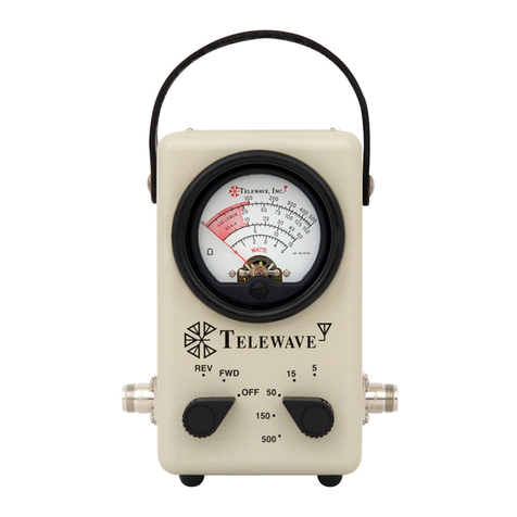
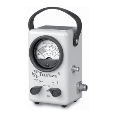
Watt Meter. Figure 1-1 illustrates
the
Model
44
RF
Watt Meter.
Its
features
include:
• Does
not
require
inserts,
• Does
not
require
bandswitching,
• Displays five
power
ranges,
• Meas1ues 1
to
500
Watts,
• Provides 5 Watts full scale,
•
Frequency
range
is
20
to
1000
MH
z,
• Measures
incident
and
reflected
power,
•
Optionally
available
with
type
Nor
UHF
connectors,
• Lightweight, rugged
and
easy
to
carry.
1.02
The
instrument
integrates
two
broad-band
directional
couplers
for
measuring i
ncident
and
reflected
power,
detectors,
ranging,
calibration
and
display. This wi
de
band
and
dynamic
range
instrument
does
not
require
inserts
or
band
switching.
1.03 A
20
µA
taut
band
meter
movement
is used
to
display
l,he
measured
power
providing
the
measurement
accuracy
necessary
to
tune
low
power
portable
transmitters.
1.04
The
user
is
provided
with
a
convenient,
easy
to
read,
vo
ltage
standing
wave
ratio
(VSWR)
chart
on
the
rear
of
the
instrument
for
determining
VSWR from
the
measured
incident
and
reflected
powe
r levels.
1
.05
A die-cast
metal
case
houses
the
instrument
for
rugged
field use.
The
Model
44
is ideally
suited
for
mobile,
marine
and
aircraft
applications
as well as
base
stations.
Page
3

www.SteamPoweredRadio.Com
7034
2. PHYSICAL DESCRIPTION
2.01
The
physical details
of
the
Model
44
Broad
Band
RF
Watt
Meter
are
illustrated
in
Figure
2-1
and
the
functions
of
these
elements
are
tabulated
for
the
user
in
Table
2-1.
2.02
The
instrument
is designed
for
rugged field use
and
is
housed
in
a die-cast
metal
case
with
a l
eather
carrying
strap.
Measurement
circuits
in
the
watt
meter
draw
a few
microwatts
from
the
user's
rf
source
to
power
the
instrument
making
it
unnecessary
to
supply
ac
power
or
batteries. A carrying case (Model
TC44)
is
furnished
opt
ionally.
Table 2-1 -Model
44
Broad Band
RF
Watt Meter -
Controls and Indicators
Key Element
1 In
put
Connector
2
Output
Connector
3 Mode
Switch
Function
Provides a
connection
to
the
RF
source,
e.g.,
RF
power
amplifier
or
transmitter.
Mates
with
a
type
N
connector.
Provides a
connection
to
the
RF
load,
e.g.,
antenna
or
dumm
y
load.
Mates
with
a
type
N
connecto
r.
(1)
OFF
-Provides
protection
to
meter
during
instrument
transit.
(2)
FWD -
(Forward)
- Displays
the
incident
power.
(3)
REV
-(Reverse) -Displays
the
reflected
power.
4
Power
Range Displays five
RF
power
ranges.
Page
5

www.SteamPoweredRadio.Com
7034
K
ey
5
6
7
8
Table 2-1 -
Mod
el
44
Broad Band
RF
Watt
Meter
-
Controls
and
Indic
ators
(Continued)
El
ement
Func
t
ion
RF
Range Provides range sensitivity for
the
display.
Switch
Identification
Provides
the
user
with
the
model
and
Label serial
number
of
the
instrument.
VSWR
Chart
Provides
the
user with
information
for
determining
the
VSWR from
the
mea-
sured
incident
and
reflected power.
Carrying Provided
for
transporting
the
instrument.
Strap
Page 6

www.SteamPoweredRadio.Com
703
4
3. FUNC
TIONAL
DES
CR
IPTI
ON
3.01
The
Model
44
RF
Watt
Meter
is
made
up
of
two
major
sections.
Refer
to
the
schematic
diagram in
Figu
re 3-1
for
this
description.
(a) A D
ual
RF
Directional
Coup
l
er
with
directivity
of
greater
than
25
dB.
(b) A
voltmeter
circuit.
Five ranges are
provided.
3.
02
The
50
Ohm
coaxial
Dual
Directional
Coupler,
Al ,
samples a small
amount
of
the
power
delivered
to
the
rf
load,
the
incident
power.
A small
amount
of
the
power
reflected
from
the
rf
load is also
sampled.
The
coupler
also
incorporates
two
rf
detectors
which deliver
de
output
voltages
proportional
to
the
sampled
rf
power.
3.03
The
Mode
Switch,
Sl,
determines
which
of
these
voltages is displayed
on
the
voltmeter,
Ml.
The
RF
Power Range
Switch,
S2,
selects
the
appropriate
range
and
calibration
resistors
for
the
power
to
be
measured.
Each
range is
provided
with
an
adjustable
potentiometer
for
range
calibration.
3.04 Meter,
Ml,
is provided with five scales which
correspond
to
the
RF
Power
Range
Switch
positions
.
The
lower
third
of
the
meter
scale
is
shaded
red,
alerting
the
user
to
switch
to
a
lower
power
range for
fu
ll
instrument
accu
r
acy.
An OFF
position is provided
on
the
Mode
Switch,
S1,
whi
ch
shunts
out
the
meter
movement
. This provides
dampening
for
the
sensitive
meter
when
the
instrument
is being
transported.
Page 7

www.SteamPoweredRadio.Com
7034
4.
SPECIFICAT
IO
NS
4.01
Table 4-1 will provide
the
user
with
tabulated
specifi-
cations
for
the
Telewave
Model
44
Broad
Band
RF
Watt
Meter. These are
provided
to
assist
the
user
in
formulating
the
applications,
acceptance
criteria
and
for
periodic
recalibration
of
this
instrument.
Minor
deviations
from
these
specifications
which
do
not
affect
the
performance
of
the
Model
44
Watt
Meter
are
excluded
from
the
warranty
.
Table 4-1 - Model
44
Broad Band
RF
Watt
Meter Specifications
Par
ameter
Frequency
Range
Accuracy,
20
to
100
MHz
100
to
512
MHz
512
to
1000
MHz
Power
Ranges
Primary Line
Impedance
VSWR
RF
Connectors
Standard
Optional
Dimensions
Height
Width
Depth
Weight
Characteristic
20
to
1000
MHz.
±6
per
cent
with Figure 7-1 curve.
±5
percent.
±6
per
cent.
5,
15
,
50,
150
and
500
Watts.
50
Ohms
nominal
.
1.1
maximum
.
Type
N.
Type
UHF.
These
connectors
r
educe
the
frequency
accuracy
in
the
512
to
100
0 MHz range.
16.83
cm
(6-5/8
in.)
10.16
cm
(4
in.)
8.26
cm
(3-1/4
in.)
1.36
kg
(3
lbs.)
Pag
e 9

www.SteamPoweredRadio.Com
7034
5. OPERATION
Unpacking
5.01
After
the
Model
44
RF
Watt
Meter
arrives,
examine
the
shipping
containe
r
for
visible loss
or
damage. Carefully
unpack
the
watt
meter
and
examine
the
exterior
fo
r damage.
IM
PORTANT
The
Mod
el
44
RF
Wall
Meter
is
caref11/ly t
ested,
inspect
ed
and
packed
before
leav
in
g
rh1•
Tel
ewave
factory.
Claims
for
loss
or
damage
sus
tained
ill
transit
should
be
made
upon
the
carrier,
NOT
TO
Telewave
In
c.,
as
follows:
( I }
Visible
!,oss
or
Damage
-A
ny
evidence
11111
st
be
noted
Oil
rhe
freighr
bill
or
express
delivery
sh
eet.
The
form
required
to
f
il
e
such
a claim
will
be
supplied
by
the
carrier.
(2)
Concealed
loss
or
Damage
-
Thi
s
damage
does
1101
becom
e
eviden
t
until
after
rhe
wa
tt
meter
is
unpacked.
When
th
e
damage
is
di
scovered
,
make
a
written
req
u
est
for
i11sp
ec
1ion by
th
e c
arri
er's
agent
w
ithin
fif
t
een
days
of
the
deliver
y elate.
File
a
clai
m wi
th
th
e carri<'r.
RF Con
nection
s
5.02
The
following
procedure
will
as
s
ist
the
user
in
prepara-
tion
for
making
an
rf
power
measur
e
ment.
Refer
to
Figure 2-
1.
Step
Procedure
1 Remove
the
rf
power
from
the transmission line.
10

www.SteamPoweredRadio.Com
7034
Step
Procedure
2
Set
the
RF
Range
Switch
to
the
500
Watt position.
3
Connect
the
RF
Source
to
the
Model
44
input
connector.
4
Connect
the
RF
Load
to
the
Model
44
output
connector.
Incident Power Measurement
5.03
The
following
procedure
will assist
the
user in
makjng
an
incident
or
forward
power
measurement.
Refer
to
Figure 2-1.
Step
Procedure
1
Set
the
Mode Switch
to
the
FWD
position.
2 Apply
rf
power
to
the
transmission line.
3 Move
the
RF
Range
Switch
to
a
lower
range
if
necessary
to
obtain
a
reading
in
the
upper
two-thirds
of
the
scale.
4
Note
the
meter
reading.
Apply
a
Correction
Factor
if
the
frequency
is
from
25
MHz
to
100
MHz.
Refer
to
Figure 7-1.
Reflected Power
Me
as
urement
5.04
The
following
procedure
will assist
the
user
in
making
a r
eflecte
d
or
reverse
power
measurement.
Page 11

www.SteamPoweredRadio.Com
7034
Step
Procedure
1
Set
the
Mode
Switch
to
the
REV
position.
2
Same
procedure
as
Step
2
of
5.03.
3
Same proc(>dure
as
Step
3
of
5.03.
VSWR Calculation
5.05
The
following
procedure
will assist
the
user
in
df'ter-
mining
the
Voltage
Standing
Wave Ratio.
Step
Procedure
1
Perform
the
procedures
outlined
in
5.03
and
5.04.
Record
the
true
incident
and
reflected
power.
2
Refer
to
the
VSWR
Chart
on
the
rear
of
the
instru-
ment
or
Figure 7-2.
Apply
the
reading,
Step
1 above,
to
the
chart.
3
The
VSWR is read
from
the
nearest,
sloping
line.
£?or
higher
accuracy,
calculate
the
VSWR
by
this
formula:
l+
V:
BEY
(Watts}
f~
O
(Watts)
VSWR = p
BEY
(Watts)
1 - p
FWD
(Watts)
Page 12

www.SteamPoweredRadio.Com
7034
True Power
at
loa
d Calcul
at
ion
5.06
The
following
procedure
will assist
the
user
in
deter-
mining
the
actual
power
delivered
to
the
load.
S
tep
Procedure
1 P
erform
the
procedures
outlined
in
5.03
and
5.04.
Record
the
true
incident
and
reflected
power
.
2
Subtract
the
reflected
power
from
the
incident
power.
This
difference
is
the
true
power
at
the
load.
D
irec
tivity Error
5.07 Directivity
error
results
from
the
effect
of
imperfect
directivity in
the
Dual Directional Coupler. Directivity
is
the
ability
of
the
coupler
to
sense
power
flowing
in
one
direction
and
be insensitive
to
any
power
which
may
be
flowing in
the
reverse
direction.
T
he
directivity
error
is
included within
the
specified
instrument
accuracy
of
±5%.
In
sertion
Er
ro
r
5.08
When
the
rf
load
and
rf
source
are
well
matched,
any
error
contributed
by
inserting
the
Model 44
RF
Watt Meter is negligible.
At
VSWR's
of
over
1.5
and
at
frequencies
above
100
MHz,
the
transmission line
length
becomes critical. Since
the
impedance
on
either
side
of
1/2 wavelength
is
identical,
a length
of
coaxial cable
can
be
added
to
the
Model
44
to
equal
1/2
wavelength,
thus
elimi-
nating
any
error
due
to
the
width
of
the
watt
meter.
5.09
The
chart
shown
in Figure 7-3
shows
the
length
of
RG-8/U
cable
and
connectors
vs.
frequency
which
must
be
added
when
the
user prepares a cable.
The
following
should
be
considered
when
cutting
the
cable.
Page
13

www.SteamPoweredRadio.Com
7034
(a)
lf
type
UHF-259
connecto
rs
are
used,
the
cable length
is
measured
from
tip
to
tip
of
the
center
pin
of
the
plugs.
(b)
If
type
N
connectors
ar
e used,
the
cable
length is
measured
from
end
to
end
of
the
oute
r
conductor
of
connectors.
6.
MA
INTENANCE
6.01 The Model
44
RF
Watt
Meter
is designed
with
high-
reliability
components
and
operates
on
low
de
pow
er
levels.
It
can
be
e
xp
ected
to
operate
at
peak
performance
for
long
intervals. A
periodic
cali
bration
check
conducted
by
an
rf
standards
laboratory
is
rec
ommen
ded
at
least
once
a year.
Warra
nty
Service
6.02
It
is
intended
that
the
Model
44
be
maintain
ed
on
a
unit-replacement
basis
during
the
warranty.
Fau
l
ty
units
should
be
returned
to:
Manager, Customer Serv
ice
TELEWAVE, INC.
2166
Old
Middlefie
ld
Way
Mount
ain
Vi
ew, California
94040
(415)
968-44
00
6.03 When
mat
erial
is
returned
to
Te
lewave,
the
following
info
rma
tion
will
expedite
repair
and
return
if
it
is
included:
(a)
The
Model
44
serial
number.
Refer
to
Figure 2-1
and
Table
2-1
fo
r
ID
plate
lo
cat
ion.
I
nclude
the
date
of
purchase
and
the
Purchase
Order
Number
if
known.
(b) A
brief
statement
of
the
problem.
Page
14

www.SteamPoweredRadio.Com
7034
(c)
The
name
and
telephone
number
of
the
individual
most
familiar
with
the
problem.
Calibration
6.04
Adjustments
to
calibration
should
be
performed
by
a
rf
calibration
l
aborato
ry. Calibration
should
be
made
at
a frequency
of
250
MHz
when
possible. If
it
is necessary
to
perform
the
calibration
at
a
frequency
below
100
MHz,
consult
Figure 7-1
for
the
correction
factor.
6.05
The
calibr
ation
potentiometers
are
located
on
a
pc
assembly inside
the
instrument.
Refer
to
Figure 2-1.
--
Figure 6-1 - Calibra
tion
Potentiom
eters
and
Parts L
oca
tion
MP3
R1
R15
R3
R7
R11
Al
Page 15

www.SteamPoweredRadio.Com
7034
Vanabl
e
RF
So
urce
Low
Pass
F1Jtc,
ln
•Lme
Power
Aeforeoce
Model
44
Under
Cal1brat
,on
Figure 6-2 -Calibration
Equipment
Set-up
RF
load
Remove
the
four
bumper
screws from
the
rear
panel. Remove
the
rear
panel. Figure 6-1 illustrates
the
calibration
poten-
tiometer
locations.
(a) Forward R 1 - 5 Watt range,
R 3 -
15
Watt range,
R 7 -
50
Watt range,
Rll
-
150
Watt range,
R15
-
500
Watt range.
(b)
Reverse R 2 - 5 Watt range,
R 6 -
15
Wattrange,
Rl0
-
50
Watt range,
R14
-
150
Watt range,
R19
-
500
Watt range.
6.06
Refer
to
Figure 6-2,
the
Calibration
Equipment
Require-
ments.
Perform
the
calib
ration
as follows:
Step Procedure
1
Set
the
rf
source
to
250
MHz.
2
Set
the
watt
meter
Mode Switch
to
FWD position.
3
Set
the
watt
meter
RF
Range Switch
to
5 Watts.
4
Set
the
rf
source
to
5 Watts
out.
5 Adjust
Rl
until
the
watt
meter
reads 5 Watts.
6 Reverse
the
watt
meter
rf
connections
in
the
rf
line.
Page
16

www.SteamPoweredRadio.Com
7034
Step
Procedure
7
Set
the
watt
meter
Mode Switch
to
REV
position.
8 Adjust
R2
until
the
watt
meter
reads
5 Watts.
9 Reverse
the
watt
meter
rf
connections
in
the
rf
line.
10
Set
the
watt
meter
Mode Switch
to
the
FWD position.
11 R
epeat
Steps 1
thro
ugh
10
for
the
15
,
50,
150
and
50
0 Watt ranges.
12
Reinstall
the
rear
panel
and
bumper
screws.
Replaceable Parts
6.
07
Table 6-1
tabulates
t
he
replaceable parts
which
the
user
might
expect
to
replace
during
the
in
st
rumen
t lifetime.
Table 6-1 -Model
44
RF Watt Meter -Replaceable Parts List
t-
t RH
llFSr.fl•Jf'ltfltJ
ttrG
Mf
U
,.,,.
A l ;111r.:£TrtONAP
f'O
IJPI
tR
: lll11~l
T£LFWAVF
f,044
M I :,-u-1rR:
70
IIA
TRIPLE
Tr
/OH
r
MP
I
t,NO~
:
RAV!HtnN
MS
Qt
~;._
1
t◄
-H•:)t1
MF'
2 :SCJ;:fLJ:
lRl
l~jf; llt:-AI•
r~
,,
(IU/R
AU
Y
flf"SCR
l
r-
I
HIN
Mr
.I
ISTRAf'
! 1 nnu1-r,
lfLHIAVf
tll-
H4
MP
:srRFW: flllJ'tf•ffi• 6
~~,
rl-1
[Y"Vt
J
f<44
~
if(
!
Vi'+f\
rr
0.:-"~W
1
0'\%
:'.~"
(IHM 1'1t'.; U:->Olfl'.2~•
..'Ff
I R ? :
r~:
VI\~
er
0 . :1
'):W
lO\Y.
;,,r;t-,.
flHM
if!'.;
ll:t
01
f,
•."l~1?Jl
R j :R: Vt.Fi
er
n.:1
0::
u
Jo\Z
w,
(Jt,iM
err,
U'.'01Fd(),H1
R • :~;
f),'fJ
er
o.~Ju
~,\¼
I
,RI\
nMM
A~
Rrrtl
R ;
;i;
:
HO
CL
o.
:•~w
~\%
l , Al, fltlM
AT<
Ren-;
~ 6
:I<!
VAi~
er:
o.
;,~w
10\Y.
10,
fJHM
rrs
ll:-10JJd0.1ift
R 7 :R:
VAh
er
0 ,
7~,IJ
10\X
!OK
l1HM r
r~
ll:
10 I
Rl(l
~
fi
I R fl
:R:
nw
t;[
0,
:-J~if,J
"",\/.
"'
fllH1
M<
Rrn:;,
R 9
:H!
f)(ll
f(
o.,~u
~-\:!
!tit(
OHM
AR
FWl17
I R
JO
IR
!
VAR
re
o.
~~,w
1
o,x
10,
OH/I
r
rs
1no1~tn<
H
R
ll
:R:
VAH
r"
o,:-•5u
JO\¼
'."".""1K
OHM
r,~
0:-01
,e:1
rn
R
J;,
:1<:
FXlt
rr
o. 7sw
~,\'Z
JJ
s
OHM
Af<
hl
n1
R 13
:r.·
: r
'l<n
rr
o.
:,::;w
'.,\¼
~11'
Of
<M
A&
"r,(17
' R
1.
:R
:
V/\R
Cf'
O,
?f-t"-1
10\">;
:'JI,
OHM
r rs ,,:,,01R;•;,1lf
R 1--, : f.•:
VAR
cc 0 .
:,51,,1
20\:C:
;_,~t,.,
OHH
rrs
lf?OIH:'"1~11-1
r,
II,
""
F)([I
er
o.
~~
w
'S\Y.
o;,,
OII
M
Al<
1\('fl7
R
11
:Rl
rx1,
r.c
o.
2~l.i
r ,
I\
•~
F)~•h,
flHh
AO
f</:117
I R 10
IR:
VAR
rr
(}, :l!',
IJ
I()\;!
:>'jl\
OHM
('JS
ll.'Cl1t.:Y·, ·~~
R
!9
IR:
F
XII
cc
0,:"$1.J
'.:J\Z
~o
fl"M
M•
~,,:t~OI
R
.'0
If<:
f--
XI
•
rr
o . :i•,c.1
a\%
~o
fl'IH
A[•
~tfl?
s l
/C-1
Wl
ffH:
ROff'!,-;.•y ~
,·n1
r '
JU'1
U-Nft,'AI
~"lR
t·ri;,no
~
s
~
;~ilJI
Jr:,.t :
ROT/\R)
2
I'll!
l
<,
n,s
rTNH.;AI
A&
t·Al,01),1
Page 17

www.SteamPoweredRadio.Com
7034
7.
REFERENCE
7.
01
Part
7 c
on
tains
ad
ditional
information
on
t
he
Mo
del
44
RF
Watt
Me
t
er
whi
ch
the u
se
r may need to r
efe
r
to
pe
rio
di
cally.
7.02 Figure 7-1 will
furn
ish
th
e us
er
with
a
watt
me
te
r
corr
ect
ion
factor
for
power
measurements below
100
MHz. For ex
ampl
e:
Fre
qu
ency
= 95 MHz,
Ind
icated Power =
27
5 Wa
tts,
Corr
ect
ion
Fact
or for
95
MH
z=
+4%,
A
ctual
P
owe
r = (
275
W) + (9.
00
W)
=
284
Watts.
•40
_ ,
,_,__
--
•
35
'--
_,__
I
I
+30 -I -
I
-
--
>--
-
\
,_,_
_
\
--
115
\
_ , -
-\
--
•
10
'1,
...
~
-
.....
-,--
--
25
50
75 100
125
FreQuencv
. MHl
Figur
e 7-1 - Model
44
RF
Watt
Meter
Cali
bratio
n
Char
t
For
F
requencie
s
Belo
w
150
MHz
Page 18
1
50
Table of contents
Other TELEWAVE Measuring Instrument manuals
Popular Measuring Instrument manuals by other brands
Gelia
Gelia 4000070701 manual
China Electronics Technology Instruments
China Electronics Technology Instruments AV3672 Series user manual

Fluke
Fluke 1773 Calibration manual
MICRO-DESIGN
MICRO-DESIGN F100MX Operator's manual

Lumantek
Lumantek WEIVER 2.0 manual
Afriso EURO-INDEX
Afriso EURO-INDEX OWWG 3 operating instructions
Victron energy
Victron energy BMV-702 Quick installation guide
geo-FENNEL
geo-FENNEL FL 210A user manual

PCB Piezotronics
PCB Piezotronics 356B20 Installation and operating manual

MRC
MRC CO2-9904SD Operation manual
Martini Instruments
Martini Instruments MI 306 instruction manual
Konica Minolta
Konica Minolta AeroDR SKR 4000 Operation manual


