manuals.online logo
Brands
  1. Home
  2. •
  3. Brands
  4. •
  5. Telex
  6. •
  7. Intercom System
  8. •
  9. Telex Audiocom EMS-4001 User manual

Telex Audiocom EMS-4001 User manual

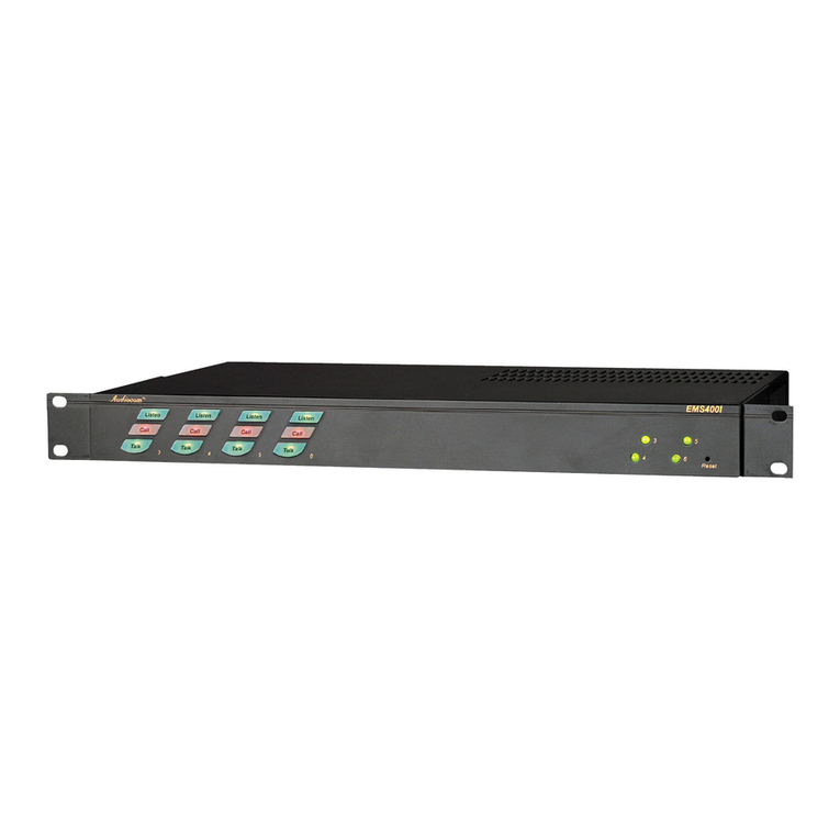
EMS-4001
Expansion Master Station
The EMS-4001 adds four powered intercom channels to an MS-2002 or MS-4002 Master Station, and it provides talk, listen
and call buttons for the added channels. Up to four EMS-4001 Expansion Master Stations may be connected to the MS-2002
or MS-4002 to can add up to 16 channels (20 channels total). The MS-2002 or MS-4002 microphone is used to talk back to the
EMS-4001 channels, and the MS-4002 speaker is typically used for listening. However, there are also separate speaker jacks
on the back panel of the EMS-4001 for independent monitor speakers, if desired. There are also 4 additional program inputs on
the back of the EMS-4001, one for each added channel.
Simplied Expansion
The EMS-4001 integrates four powered channels with talk,
listen, and call controls in a single rack mount unit. Saves on
rack mount hardware and eliminates power supply to expan-
sion station interconnect cables.
Compatibility and Flexibility
Connects directly to an MS-2002, MS-4002 or US-2002
Master Station to add 4 complete powered channels. Or
connects to a previous EMS-4001 or ES-4000A Expansion
Station to add another 4 powered channels (up to 18-20
channels total).
Overload/Short-Circuit Protection
Provides automatic current limiting during short circuits or
overloads. Front panel fault indicator provided for each chan-
nel. The SPS-2001 has Instantaneous Auto Reset (IAR), the
newest technology in performance and safety, which uses
a revolutionary new circuitry that dynamically monitors line
fault conditions.
Mic Kill
Turn off all microphones on a selected expansion channel, or
all channels, using the master station’s Mic Kill key.
Dedicated Program Inputs
Each expansion channel has its own program input. Con-
nect any line-level audio source for monitoring in the master
station’s speaker or headset and for routing to the expan-
sion channel if desired. When program audio is routed to
the channel it can be set to interrupt while the master station
operator is talking on the channel.
Binaural (Stereo) Listening
If the master station is equipped with external powered
speakers you can assign the EMS-4001 channels to either
right or left speaker.
Instantaneous Auto-Reset
Instantaneous Auto Reset (IAR), the newest technology in
performance and safety, which uses a revolutionary new
circuitry that dynamically monitors line fault conditions. Then,
when the fault is removed, automatically brings individual
power supply channels up.
Clear-Com Compatible
Features
Line Drawing
EMS-4001 Specications
General
Input and Output Power:
AC Input: 100-240 VAC, 50/60 Hz
Channel Power (each channel): 24 ±1 VDC, 1 A
Dimensions: 1.75” (44.5 mm) high, 19” (483 mm)
wide, 10.31” (261.9 mm) deep
Weight: approximately 4.5lbs (2kg)
Environmental Requirements:
Storage: -20°C to 80°C; 0% to 95% humidity, noncon-
densing
Operating: -15°C to 60°C; 0% to 95% humidity, non-
condensing
Program Input Connectors
Input Level: 100mV maximum
Voltage Gain: 25 ±3 dB
Output Level (to intercom channel): 1.0Vrms nominal,
2.3Vrms max.
Input Impedance: 75k ohms
Common Mode Rejection: Greater than 50 dB
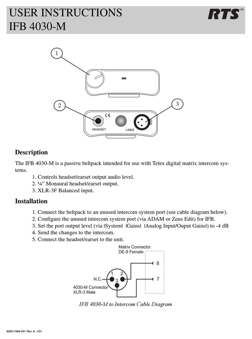
Connector type: DB9F female, 9-pin D-Sub
Pin 1: Common
Pin 2: Channel 3 program in low
Pin 3: Channel 4 program in low
Pin 4: Channel 5 program in low
Pin 5: Channel 6 program in low
Pin 6: Channel 3 program in high
Pin 7: Channel 4 program in high
Pin 8: Channel 5 program in high
Pin 9: Channel 6 program in high
Intercom Channels, Balanced Mode (BAL/UNBAL
switch set to BAL)
Output Level: 1 Vrms nominal
Input Impedance: 300 ohms ±10%
Bridging Impedance: greater than 10,000 ohms
Sidetone: -40 dB, 35 dB adjustable range
Figure 4 - EMS-4001 sidetone adjustment locations.
Call Signaling:
Send: 20 kHz ±100 Hz, 0.5 Vrms ±10%
Receive: 20 kHz ±800Hz, 100 mVrms
Mic-Kill Frequency:
Send: 24 kHz ±100 Hz, 0.5 Vrms ±10%
Receive: 24 kHz ±800 Hz, 100 mVrms
Noise Contribution: less than -70 dB
Common Mode Rejection Ratio: greater than 50 dB
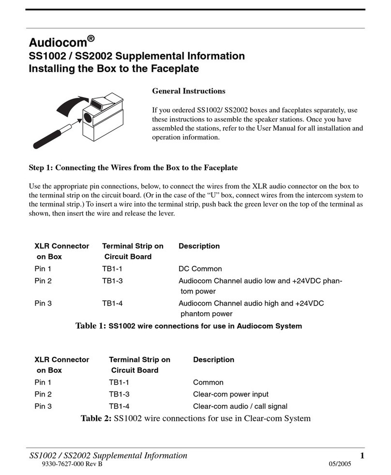
Connector type: One XLR-3M for each channel
Balanced Conguration Pinouts
Pin 1: DC/audio Common
Pin 2: Intercom audio low and +24 VDC output
Pin 3: Intercom audio high and +24 VDC output
Intercom Channel, Unbalanced Mode (BAL/UNBAL
switch set to UNBAL)
Output Level: 2 Vp-p (750 mVrms)
Input Impedance: 200 Ohms ±10%
Bridging Impedance: greater than 10k ohms ±5%
Call Signaling:
Send: 11 ±3 VDC
Receive: 4 VDC minimum
Connector Type: One XLR-3M for each channel
Pin 1: Common
Pin 2: +30 ±1 VDC output
Pin 3: Intercom audio high
Expansion Input/Output
Connector Type: 1/8” Stereo phone jack
Tip: Talk output
Ring: Listen input
Sleeve: Common
Ordering Information
EMS-4001
4 channel expansion station with 2.0 amp power sup-
ply with instantaneous auto reset in a single unit.
Catalog Number: 90007713000
This specications information is preliminary and is subject to change without notication.
Brand names mentioned are the property of their respective companies.
Contact Information
Telex Communications, Inc.
12000 Portland Avenue South
Burnsville, Minnesota 55337
Telephone: (800) 392-0498
Fax: (800) 323-0498
Form Number: 9320-7713-000 Rev B
Date: December, 2006
Other manuals for Audiocom EMS-4001

2

Other Telex Intercom System manuals

Telex 4030 User manual

Telex

Telex 4030 User manual

Telex RadioCom BTR-300 User manual

Telex

Telex RadioCom BTR-300 User manual

Telex 4030 User manual

Telex

Telex 4030 User manual

Telex CM300 User manual

Telex

Telex CM300 User manual

Telex BP-325 User manual

Telex

Telex BP-325 User manual

Telex Legacy XO-1 User manual

Telex

Telex Legacy XO-1 User manual

Telex RadioCom TR-200 User manual

Telex

Telex RadioCom TR-200 User manual

Telex Audiocom SS-2002 User manual

Telex

Telex Audiocom SS-2002 User manual

Telex Audiocom IC-4M User manual

Telex

Telex Audiocom IC-4M User manual

Telex RadioCom TR-300 User manual

Telex

Telex RadioCom TR-300 User manual

Telex RadioCom BTR-300 Administrator guide

Telex

Telex RadioCom BTR-300 Administrator guide

Telex ICW-6 User manual

Telex

Telex ICW-6 User manual

Telex EKP-832 User manual

Telex

Telex EKP-832 User manual

Telex RadioCom BTR-800 User manual

Telex

Telex RadioCom BTR-800 User manual

Telex Audiocom BP-2002 User manual

Telex

Telex Audiocom BP-2002 User manual

Telex Audiocom SPS-2000 User manual

Telex

Telex Audiocom SPS-2000 User manual

Telex Audiocom EMS-4001 User manual

Telex

Telex Audiocom EMS-4001 User manual

Telex RadioCom BTR-500/600C User manual

Telex

Telex RadioCom BTR-500/600C User manual

Telex RADIOCOM BTR-300B User manual

Telex

Telex RADIOCOM BTR-300B User manual

Telex Audiocom SS-1002 Manual

Telex

Telex Audiocom SS-1002 Manual

Telex IFB-1000 User manual

Telex

Telex IFB-1000 User manual

Telex Audiocom WM1000 User manual

Telex

Telex Audiocom WM1000 User manual

Telex Vega IP-1616 User manual

Telex

Telex Vega IP-1616 User manual

Telex Legacy XO-1 User manual

Telex

Telex Legacy XO-1 User manual

Popular Intercom System manuals by other brands

urmet domus IPerCom 1741 Installation handbook

urmet domus

urmet domus IPerCom 1741 Installation handbook

urmet domus 1717 manual

urmet domus

urmet domus 1717 manual

ASL INTERCOM PRO Series user manual

ASL INTERCOM

ASL INTERCOM PRO Series user manual

NuTone LA522WH Installation & operating instructions

NuTone

NuTone LA522WH Installation & operating instructions

Radio Shack 43-222B owner's manual

Radio Shack

Radio Shack 43-222B owner's manual

ARC LMLR-710 manual

ARC

ARC LMLR-710 manual

Fermax MEET 1W Installer manual

Fermax

Fermax MEET 1W Installer manual

Savant ITP-E8000V2x Quick reference guide

Savant

Savant ITP-E8000V2x Quick reference guide

Elvox PETRARCA 6020 Installation and operation manual

Elvox

Elvox PETRARCA 6020 Installation and operation manual

AAS PhoneAire 16-1050 Installation and programming instructions

AAS

AAS PhoneAire 16-1050 Installation and programming instructions

Toa EXES-6000 Specifications

Toa

Toa EXES-6000 Specifications

Commax CDV-352HD user manual

Commax

Commax CDV-352HD user manual

Aiphone LAF-1B installation manual

Aiphone

Aiphone LAF-1B installation manual

Code Blue PHXS01 Admin guide

Code Blue

Code Blue PHXS01 Admin guide

Mircom TX3-TOUCH-S15B-WR Installation

Mircom

Mircom TX3-TOUCH-S15B-WR Installation

Vimar K40916 user manual

Vimar

Vimar K40916 user manual

Aiphone MC-60/4 Specifications

Aiphone

Aiphone MC-60/4 Specifications

2T Technology Voyager Voice Sleek Installation & user manual

2T Technology

2T Technology Voyager Voice Sleek Installation & user manual

manuals.online logo
manuals.online logoBrands
  • About & Mission
  • Contact us
  • Privacy Policy
  • Terms and Conditions

Copyright 2025 Manuals.Online. All Rights Reserved.