Telkonet Aida Owner's manual
Aida
Installation, Operation, & Maintenance Guide (IOM)

CONTENTS
Updates 3
Chapter 1: Overview 1
Intended Audience 1
What is Aida? 1
What Can the Telkonet Thermostat Do? 1
Sample Use Cases 1
Maximum Number of Associated Devices 2
How to Get Support 2
FCC Compliance Statement 2
Chapter 2: Installation 4
Voltage Options-Summary 4
Required Equipment 5
Installation - High Voltage (Non-Class 2) 9
Installation - Low Voltage (Class 2) 14
Chapter 3: Add Ons 17
About Wiring the Aida 17
NTC Probe 17
CT Inputs 17
Chapter 4: User Interface 19
Chapter 5: Appendices 20
Proportional Valve Control; Analog Output 20
JBox Mounting Options 21
2
Aida IOM

UPDATES
Revision 4: add FCC RF Exposure statement and Canadian RF Exposure Statement
3
Aida IOM

Chapter 1: Overview
INTENDED AUDIENCE
These instructions are intended for:
lInstallers who are either Telkonet certified installers or have completed a series
of Telkonet micro-training courses (contact your Telkonet Project Manager for
details)
lFacilities engineers who will maintain Telkonet devices
WHAT IS AIDA?
Aida thermostats are like traditional thermostats in that they are wired to the HVAC
system. They feature six relays, and the occupants interact with them to adjust room
climate.
Aida thermostats are different than traditional thermostats in that they are “smart”.
Aida thermostats feature occupancy sensors, so it is important to install them in the
location where they can best sense occupancy
WHAT CAN THE TELKONET THERMOSTAT DO?
The Telkonet thermostat will automatically learn and adapt to the heating and cool-
ing patterns of each room.
For example, a room on the east side of a building will receive direct sunlight in the
morning and will either need less heating or more cooling. However, as the day pro-
gresses, the room will need more heating or less cooling as it moves into the shade. A
Telkonet thermostat will continually monitor the room, learn its patterns, and adjust
its heating and cooling profiles accordingly.
Telkonet thermostats also learn and adapt to occupant schedules. When a room is
unoccupied, the thermostat will enter an energy-saving mode, allowing the room to
drift away from the desired set point. During this drift period, the thermostat will oper-
ate the HVAC unit less often, reducing energy costs. When the room becomes occu-
pied again, the Telkonet Recovery Time™ technology built into each thermostat will
return the room to the setpoint without the occupant noticing.
SAMPLE USE CASES
Telkonet thermostats are available in several possible configurations, to address spe-
cific requirements of multiple applications including hotels, classrooms, university
housing, military residence halls, senior living facilities, multi-dwelling units, and a
wide variety of other commercial and industrial spaces.
Chapter 1: Overview 1
Aida IOM

MAXIMUM NUMBER OF ASSOCIATED DEVICES
Aida can accept associations with up to 32 total Telkonet and other compatible wire-
less devices, such as occupancy sensors and door contacts.
HOW TO GET SUPPORT
DURING INSTALLATION
Contact your dedicated Telkonet Project Manager if you have any installation ques-
tions.
AFTER INSTALLATION
Contact the Telkonet Support Center at [email protected], (414) 302-2203, or the
phone number you were provided at installation, based on your support subscription
plan.
FCC COMPLIANCE STATEMENT
This equipment has been tested and found to comply with the limits for a Class B
digital device, pursuant to Part 15 of the FCC Rules. These limits are designed to
provide reasonable protection against harmful interference in a residential install-
ation. This equipment generates, uses and can radiate radio frequency energy and if
not installed and used in accordance with the instructions, may cause harmful inter-
ference to radio communications. However, there is no guarantee that interference
will not occur in a particular installation. If this equipment does cause harmful inter-
ference to radio or television reception, which can be determined by turning the
equipment off and on, the user is encouraged to try to correct the interference by one
or more of the following measures:
* Reorient or relocate the receiving antenna.
* Increase the separation between the equipment and receiver.
* Connect the equipment into an outlet on a circuit different from that to which the
receiver is connected.
* Consult the dealer or an experienced radio/TV technician for help.
Operation with non-approved equipment is likely to result in interference to radio
and TV reception. The user is cautioned that changes and modifications made to the
equipment without the approval of the manufacturer could void the user's authority
to operate this equipment.
FCC RF Exposure Statement: To comply with FCC RF exposure compliance require-
ments, the device must be installed to provide a separation distance of at least 20 cm
from all persons.
Chapter 1: Overview 2
Aida IOM

CANADIAN COMPLIANCE STATEMENT
This device contains licence-exempt transmitter(s)/receiver(s) that comply with Innov-
ation, Science and Economic Development Canada’s licence-exempt RSS(s). Oper-
ation is subject to the following two conditions:
(1) This device may not cause interference.
(2) This device must accept any interference, including interference that may cause
undesired operation of the device.
Canadian RF Exposure Statement: This equipment complies with Canada radiation
exposure limits set forth for an uncontrolled environment. This equipment should be
installed and operated with minimum distance 20 cm from the radiator and your
body.
L’émetteur/récepteur exempt de licence contenu dans le présent appareil est con-
forme aux CNR d’Innovation, Sciences et Développement économique Canada applic-
ables aux appareils radio exempts de licence. L’exploitation est autorisée aux deux
conditions suivantes
1) L’appareil ne doit pas produire de brouillage;
2) L’appareil doit accepter tout brouillage radioélectrique subi, même si le brouillage
est susceptible d’en compromettre le fonctionnement.
Declaration d'exposition aux radiations: Cet equipement est conforme aux !imites
d'exposition aux rayonnements IC etablies pour un environnement non controle. Cet
equipement doit etre installe etre utilise avec un minimum de 20 cm de distance
entre la source de rayonnement et votre corps.
FCC ID
Aida: tbd
ABOUT THIS PRODUCT
This product is intended for outlet box mounting.
This product utilizes relays as the load-controlling/switching elements.
This product does not include GCFI functionality (as commonly required for systems
that control in-floor radiant electric heat).
This product has a “marked off” position but have the capacity to open only one pole
of the load supply circuit. Accordingly, this product is limited to the control of loads
having only one ungrounded supply pole (120 or 277 V ac circuits). In the off position
the ungrounded pole is opened when the thermostat is placed in the off position.
This product is not suitable for safety or limiting applications.
This product is not suitable for plenum applications/installations.
Chapter 1: Overview 3
Aida IOM

Chapter 2: Installation
VOLTAGE OPTIONS-SUMMARY
High Voltage Installation Option
(30 V or greater) Low Voltage Installation Option
There is only one installation option:
1. JBox with Vertical Mud Ring Mount:
requires adapter plate as shown in
FIGURE 3.
There are 3 options. Select based on code
and desired look:
1. Drywall mount: no conduit required;
no JBox adapter plate required.
2. JBox with Vertical Mud Ring Mount:
requires adapter plate .
3. JBox with Horizontal Mud Ring
Mount.
Chapter 2: Installation 4
Aida IOM

REQUIRED EQUIPMENT
Required Equipment High
Voltage
Low
Voltage
Anchors: EZ-Lock plus provided screws: 4 – 50 lb. (if drywall
mount) x
Backplate (included) x
Drill x x
Aida (included) x x
Electrical tape x x
Flathead screwdriver x x
JBox (if applicable) (not included) x x
Level x x
Screw Terminal Block as applicable (included) x x
Pen x
Screwdriver-Phillips Head x x
Screwdriver-precision set x
Screws-four #5 ½” coarse thread (vertical JBox mount) x x
Screws-two #6-32 1” (vertical or horizontal JBox mount) x x
Speed nut (if applicable) x
UL rated caulk x x
Voltmeter x x
Wire harnesses as applicable (included) x
Wire nuts x x
Wire stripper x x
Chapter 2: Installation 5
Aida IOM
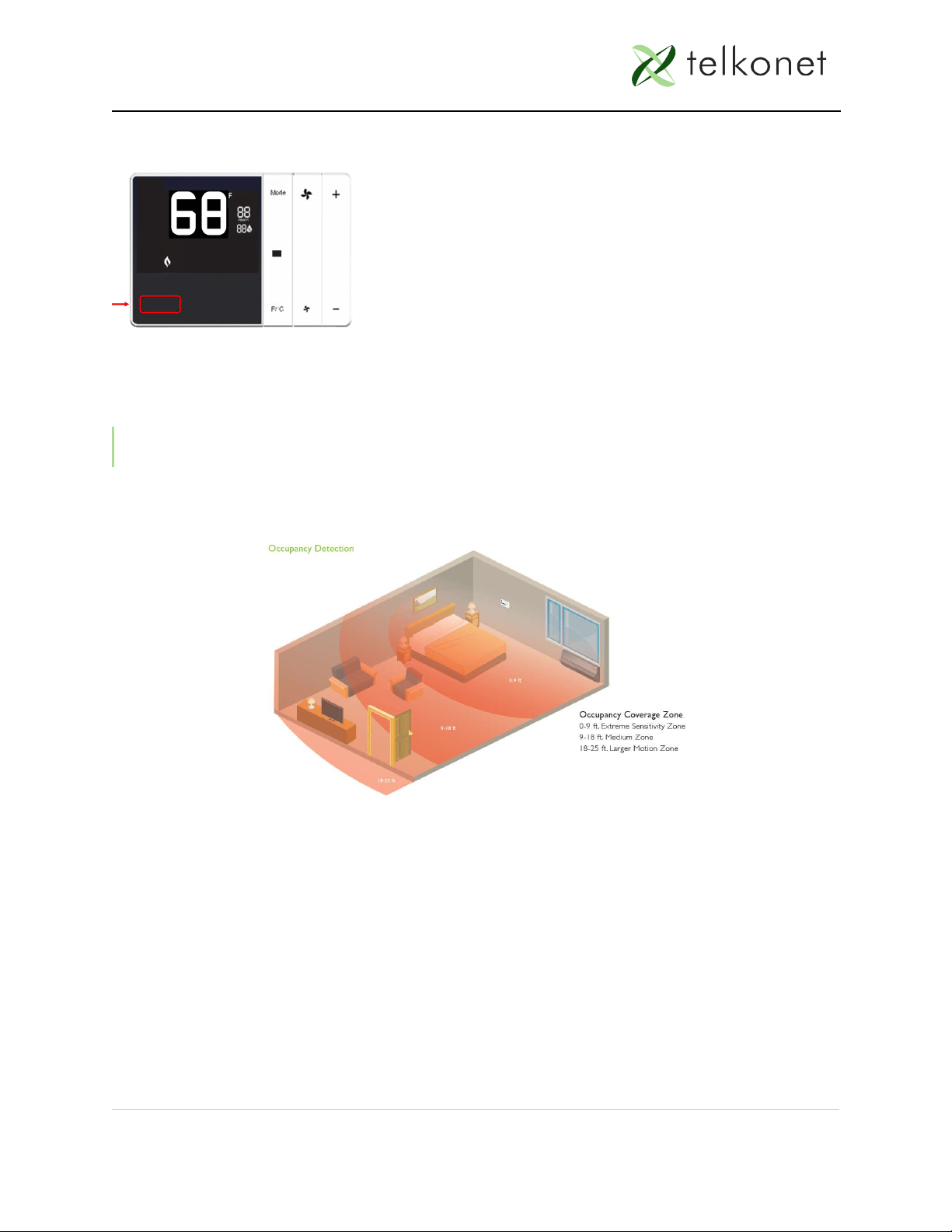
LOCATION PLANNING
The Aida features a passive infrared (PIR) occupancy sensor, so where you install it is
important. If you install it in an out-of-the-way area where it cannot sense occupancy,
the heat or air conditioning will be more likely to shut off or drift while the room is
occupied.
NOTE: Be sure to install the Aida within view of the bed as shown below.
SENSITIVITY ZONES
Chapter 2: Installation 6
Aida IOM

Mounting Con-
siderations Best Practices
Distance to Occupant
If the occupants will likely
be stationary (e.g., sleeping
in bed)…
position within 0-9 feet of
their expected location.
If the occupants will move
occasionally (e.g., working
at a desk)…
position within 18 feet of
their expected location.
If the occupants will move
regularly (e.g., walking
down a hall) …
position within 25 feet of
their expected location.
The thermostat has a 140° wide horizontal viewing
angle.
If no door contacts or remote occupancy sensors are
used in a residence, then the thermostat should either
be located with 9 feet of the bed with an unobstructed
view or have delays adjusted with "night locking" to pre-
vent setback during the evening hours.
PLACEMENT GUIDELINES
Placement Guidelines
Point toward main sleeping area if possible (max 9' from bed)...
...otherwise, point to center of room
Mount ON wall, notIN wall
Vents in backplate require proper air flow
Standard height is 60" from finished floor; ADA height is above 15" and below 48"
Mount on an interior wall if possible
Chapter 2: Installation 7
Aida IOM

Placement Guidelines
Avoid spinning fan blades
Avoid direct sunlight
Avoid heat registers
Avoid heat and cold sources in walls (e.g. exterior walls with poor circulation, walls
with pipes circulating hot water, walls near radiators, etc.)
Chapter 2: Installation 8
Aida IOM

INSTALLATION - HIGH VOLTAGE (NON-CLASS 2)
CAUTION!
lHigh voltage installation should only be performed by a qualified heating & air
conditioning contractor or licensed electrician.
lFailure to understand and follow all instructions carefully before installing or
operating this device could cause personal injury and/or property damage.
lAll wiring must conform to local and national electrical ordinances and codes.
lPrevent electrical shock, personal injury, and equipment damage: prior to install-
ation or service, disconnect system’s electric power at main fuse or circuit
breaker box.
1. Ensure the JBox (not provided by Telkonet) has been installed with a vertical
single gang mud ring.
2. Turn off power at the Aida or mounting location using a disconnect switch or
breaker lockout/tag out on appropriate breaker panel.
3. Test that power is off by using a voltmeter.
4. Strip the LINE wire back 0.25 inches.
5. Cap the LINE wire with a wire nut or electrical tape.
6. Cut the COMMON wire so the copper is flush with the insulation.
7. Strip all wires except for COMMON back 0.25 inches.
8. Remove the safety screw from the top of the thermostat using the Phillips head
screwdriver
9. Separate the backplate from the thermostat: use a flathead screwdriver to
GENTLY press the tab next to the screw hole to allow the thermostat to pop
open. WARNING: Using too much force can break the tab.
10. Place thermostat backplate against the JBox adapter plate. The adapter plate
and backplate holes should align if both are correctly oriented.
11. Connect wires and harnesses as per the pinout tables in the Tables section.
12. Mount the Aida backplate on top of the JBox adapter plate, using four #5 ½”
coarse thread screws (or other appropriate mounting screws).
13. Feed wire harnesses through the applicable holes in the backplate.
14. Connect the harnesses to the Aida.
REMINDER: Wiring to the screw terminal block must exit the enclosure at Opening A
of the backplate. Wiring to all other connectors must exit the enclosure at Opening B
of the backplate.
Class 2 and Non-Class 2 wiring must not be mixed within a junction box or conduit
run.
Chapter 2: Installation 9
Aida IOM
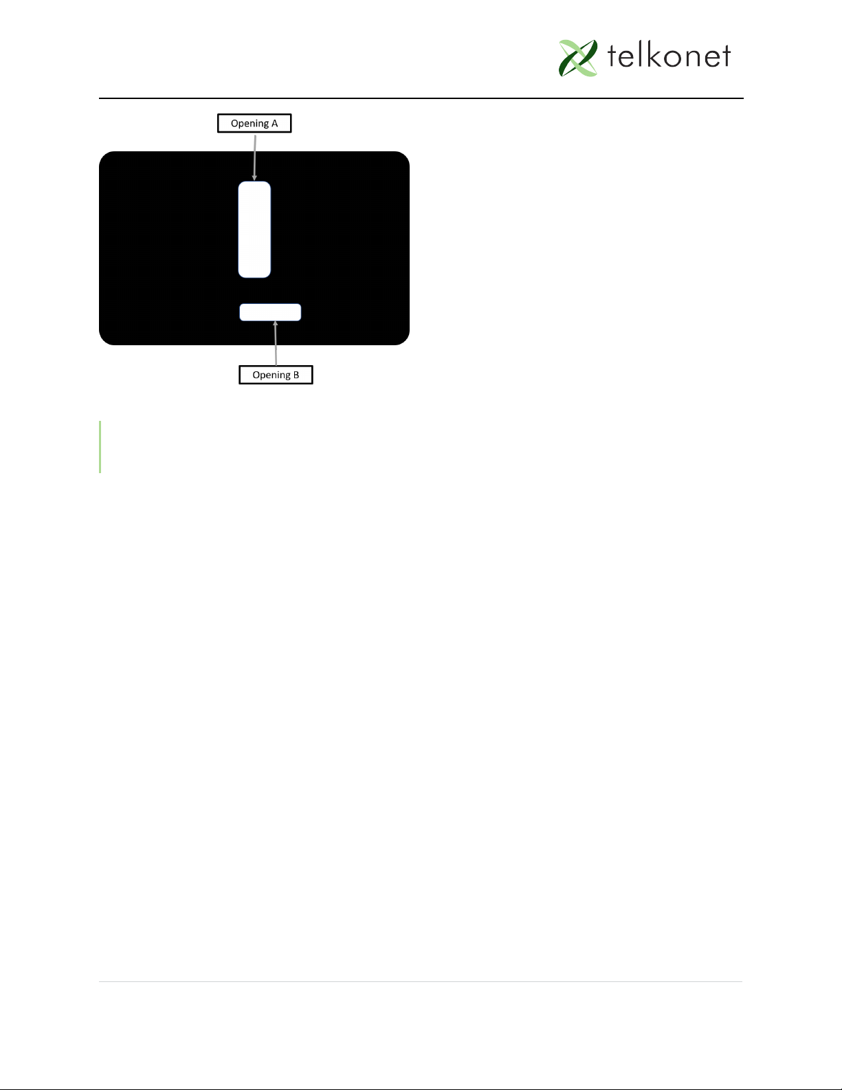
FIGURE 2-1: Backplate Openings A and B, Separate High, Low Voltage Wire
NOTE: For variable output connections: see See Proportional Valve Control; Ana-
log Output on page 20
15. Line up the hinges on the thermostat to the notches on the backplate.
16. Press the top of the thermostat tightly against the backplate.
17. Slowly lower the bottom side toward the wall. Use care not to force the faceplate
closed. If you encounter resistance, check to make sure no wires are pinched
between components.
18. Return the electrical circuit to operation. Remove all lockouts or tags from the
circuit breaker and enable any disconnects.
19. Verify the thermostat display is active.
20. Test all components to make sure that you can engage both the heat and cool,
and all supported fan settings (high, low, etc.). Wiring is complete.
21. Once the thermostat has been snapped onto the back plate, use a Phillips head
screwdriver to insert the safety screw.
Chapter 2: Installation 10
Aida IOM
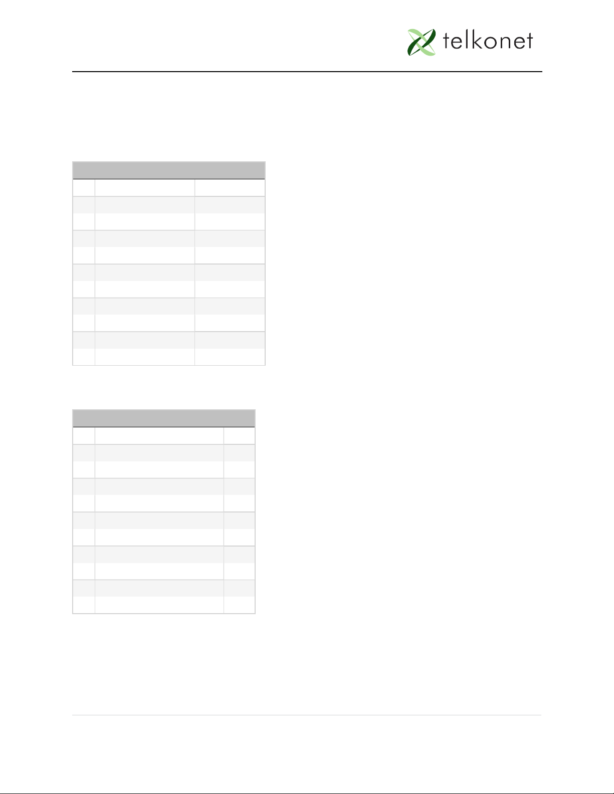
NORTH AMERICAN UL RATING SCHEDULE – NON-CLASS
Inputs
J1
Pin Signal Type
1 Dry Contact #1 Input
2 Dry Contact #2 Input
3 RS485 #1P (VDA) UART
4 RS485 #1N (VDA) UART
5 RS485 #2 P (General) UART
6 RS485 #2 N (General) UART
7 Analog Output #1 Output (0-10V)
8 Analog Output #2 Output (0-10V)
9 3.3V Output Output
10 Ground
J1 Input Table
J2
Pin Signal Type
1 Dry Contact #3 Input
2 Dry Contact #4 Input
3 NTC - Probe #1 Input
4 NTC - Probe #2 Input
5 NTC Probe Ground (shared) Input
6 CT Input A1 Input
7 CT Input A2 Input
8 CT Input B1 Input
9 CT Input B2 Input
10 Ground
J2 Input Table
Chapter 2: Installation 11
Aida IOM

Screw Terminal Block (Wire Gauge 12-28)
Pin Signal Type
1 (C) - Power In - Common Input
2 (Aux) - Auxillary Output
3 (W1) - Heat Output
4 (R) - Power In Input
5 (Y1) - Cool Output
6 (G)- Fan Output
7 (O) (G2) - Changeover / Med Fan Output
8 Switched Power 2 (G / O / W2) Input
9 (W2) (Y2) (G2)(G3) - Multi-speed Output
Screw Terminal Block Table
Other Inputs
J5 Console Port
J9 External module for Salto/Saflok
Other Inputs Table
Chapter 2: Installation 12
Aida IOM

Outputs
Position
Relay
Terminal Ratings
Current/Power Voltage Load Type Action
Type
Design
RLY1,
RLY2,
RLY3
RLY1: STB* (R) and STB (AUX)
RLY2: STB (W1/Y1) and STB (W1)
RLY3: STB (W1/Y1) and STB (Y1)
See note 1
5A 125/250/277 V
ac
General
Use
Operating
1.C
RLY5,
RYL7
RLY5: STB (G/O/W2) and STB (G)
See Note 3
RLY7: STB (G/O/W2) and STB (O)
See Note 3
See Note 1
10A 125 V ac General
Use
Operating
1.C
8A 277 V ac General
Use
1/10HP 125 V ac Motor
1/6HP 250 V ac & 277
V ac
Motor
RLY8 STB (G/O/W2) and STB (W2) See
Note 3 See Note 1
11A 277 V ac Resistive
(including
Fixed Elec-
tric Space
Heating)
See Note 2
Operating
1.A See
Note 2
1HP 250 V ac Motor
1HP 277 V ac Motor
1/2 HP 125 V ac Motor
Output Table
*STB: Screw Terminal Block
Note 1: STB (R), STB (W1/Y1), and STB (G/O/W2) – must be connected to the same pole of the same supply
circuit. Relay contacts must be connected in a same polarity fashion.
Note 2: Relay RLY8 is the only output device rated for the control of fixed electric space heating equip-
ment. This relay will de-energize when the On/Off switch is adjusted to the “OFF” position. RLY8 only
interrupts one pole of the supply circuit. Accordingly, the thermostat/relay is restricted to controlling
fixed electric space heating loads with a single ungrounded conductor – such as loads connected to a
120 or 277 V ac circuit.
Note 3: The total connected load of Relays 5, 7, and 8 should not exceed 16 Amps (through common ter-
minal J3-9STB).
Note 4: Wiring to STB must exit the enclosure at Opening A of the backplate. Wiring to all other con-
nectors must exit the enclosure at Opening B of the backplate. Class 2 and Non-Class 2 wiring must not
be mixed within a junction box or conduit run.
Chapter 2: Installation 13
Aida IOM

INSTALLATION - LOW VOLTAGE (CLASS 2)
Always ensure power has been turned off before starting installation.
1. Turn off power at the Aida mounting location using a disconnect switch or
breaker lockout/tag out on appropriate breaker panel.
2. Test that power is off by using a voltmeter.
3. Remove the safety screw from the left side of the thermostat using the hex
wrench.
4. Separate the back plate from the thermostat: Use a flathead screwdriver to
GENTLY press the tab next to the screw hole to allow the thermostat to pop
open. WARNING: Using too much force can break the tab.
5. For drywall mounting instructions, see below. For JBox vertical installation
instructions: See JBox Using Vertical Mud Ring Instructions on page 15
DRYWALL MOUNTING INSTRUCTIONS (LOW VOLTAGE)
NOTE: Requires four 50 lb. EZ-Lock anchors and screws
6. Strip the LINE wire back 0.25 inches.
7. Cap the LINE wire with a wire nut or electrical tape.
8. Cut the COMMON wire so the copper is flush with the insulation.
9. Strip all wires except for COMMON back 0.25 inches.
10. Verify the wiring now looks similar to this:
FIGURE 2-1: Drywall Mount Wiring
11. Ensure the appropriate wires are jumped between R and SW2 (assuming they
are controlling all fan and modes from the same voltage as powering the
Chapter 2: Installation 14
Aida IOM

thermostat). If installing on a heat pump, ensure that Y1 and W1 are jumped
together.
12. Connect wires and harnesses as per the tables.
13. Verify each wire is secure by gently tugging on it.
14. Hold backplate against wall at appropriate height. Using a pen, level-mark your
holes.
15. Use appropriate drill for anchor and insert anchors into holes.
16. Screw backplate to the wall and into the anchors. Re-check that it is still level.
17. Screw the wires to the screw terminal block.
18. Next: See Steps Common to all Low Voltage Installation Methods on page 16.
JBOX USING VERTICAL MUD RING INSTRUCTIONS
NOTE: Requires Telkonet JBox Adapter Plate and two #6-32 1” screws.
19. Strip the LINE wire back 0.25 inches.
20. Cap the LINE wire with a wire nut or electrical tape.
21. Cut the COMMON wire so the copper is flush with the insulation.
22. Strip all wires except for COMMON back 0.25 inches.
23. Determine which end of the adapter should be situated on top, and which end
should be situated on the bottom.
24. Mount the Aida mounting plate to the mud ring with two #6-32 1” screws.
25. Mount Aida backplate on top of JBox adapter plate, using four #5 ½” coarse
thread screws.
26. Screw down each wire to the matching screw terminal on each block. (If con-
trolling proportional valve or ECM fan, any unused wires must be capped accord-
ing to NEC standards.)
NOTE: For variable output connections: See Analog Outputs on page 21.
27. Connect all other wires and harnesses.
28. Mount the Aida backplate on top of JBox adapter plate, using four #5 ½” coarse
thread screws.
29. Feed wire harnesses through the applicable holes in the backplate. High and
low voltage wires must be fed through separate holes.
30. Connect the harnesses to the Aida.
31. Ensure backplate has appropriate jumpers between R, SW1 and SW2. If
installing on a head pump, ensure there is a jumper between Y1 and W1.
Chapter 2: Installation 15
Aida IOM

STEPS COMMON TO ALL LOW VOLTAGE INSTALLATION METHODS
33. Hook the thermostat to the hinges on the top of the backplate.
34. Line up the hinges on the thermostat to the notches on the backplate. Press the
top of the thermostat tightly against the back plate.
35. Slowly bring the top down as shown. Use care not to force the faceplate closed.
If you encounter resistance, make sure no wires are pinched between com-
ponents and that no pins are bent.
36. Once the thermostat has been snapped onto the back plate, use a Phillips head
screw driver to insert the safety screw.
37. Remove all lockouts or tags from the circuit breaker.
38. Return the electrical circuit to operation.
39. Test all components to make sure that you can engage both the heat and air
conditioning, and all supported fan settings (high, low, etc.). Wiring is complete.
NORTH AMERICAN UL RATING SCHEDULE – CLASS 2
See North American UL Rating Schedule – Non-Class on page 11
EUROPEAN CE RATING SCHEDULE – SELV
tbd
Chapter 2: Installation 16
Aida IOM

Chapter 3: Add Ons
ABOUT WIRING THE AIDA
The Aida interconnects with the existing HVAC system via standard wiring con-
ventions, using 24-277 V ac OR 24 V dc voltage supplied by the HVAC system itself.
NOTE: The Aida allows for three different control voltages.
Telkonet provides bare wire leads on all connectors. It is up to the installer to connect
these leads using an appropriate method described herein. Wiring conventions follow
industry standards; however, it is important to note that the relay configuration is
dynamic and can be modified at the factory or in the field. It is important to always fol-
low site-specific wire diagrams.
NTC PROBE
All Aida models have two inputs. Temp probes can be used for multiple purposes:
1. HVAC Discharge Air temp
2. HVAC Return Air temp
3. Supply Water Temp
4. AquaStat Mode (switches thermostat’s Heat/Cool)
For temperature probe if not using Telkonet provided external temperature probe, a
probe with a Beta R0 must match. Alternatively, a probe can be provided to Telkonet
for lab calibration. Required specifications:
US Sensor model USP10972 or equivalent, per the following:
lResistance at 25 degrees C = 10 000 ohms +/- 1%
lResistance/Temperature curve = "J"
lBeta ( 0 to 50 degrees C ) = 3892 degrees K nominal
Other models may be compatible; provide model number and specifications.
CT INPUTS
All Models have 2 inputs. The CT inputs are commonly used for monitoring/alerting
on fan motors, compressors or other equipment with excessive load or for determ-
ining a failure. The CT Inputs must be used with a compatible CT and sized appro-
priately for the load they will be connected to.
Current Transformer (CT) approved models from Sentran Corp.:
Rated loads are 100, 50, 30, 20 and 10 A respectively.
Chapter 3: Add Ons 17
Aida IOM
Table of contents
Other Telkonet Thermostat manuals


Popular Thermostat manuals by other brands

Nexans
Nexans N-COMFORT KT+ user manual

Trueway
Trueway TX986ML220-V2E manual

Intergas
Intergas Comfort Touch Installation manual & users manual

Watts
Watts FloorStat 500650-120CS user guide

One Hour
One Hour Comfort Sentry NH-522NP Installation and operating instructions

Honeywell
Honeywell Easy-To-See TRADELINE T841B user manual

Spyder Robotics
Spyder Robotics Herpstat HP user manual

Honeywell
Honeywell T8611G Chmnothern IV Instruciton

Honeywell
Honeywell RTH5100B installation instructions

Kanmor
Kanmor 501x Data brochure

Emerson
Emerson White-Rodgers 1C20 user manual

Emerson
Emerson White-Rodgers 1F75H-21PR Installation and operating instructions


