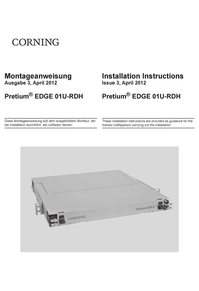
Tellabs 263DC User manual

7te11abs
technical manual
76-81263DC
rev A
practice section 81263DC-1
/81263DC-2/81263DC-3
©Tellabs, Inc., 1May
1984
all rights reserved, printed in USA
263DC
Data Station Termination Systems
-
figure
1.
2630C-1
OST
Sysfem
page 1
page 2
page 5
page
10
page
12
page
11
page
13
contents
section 1general description
section 2application
section 3installation
section 4
circuit
description
section 5
block
diagram
section 6specifications
section
7testing
and
troubleshooting
1.
general
description
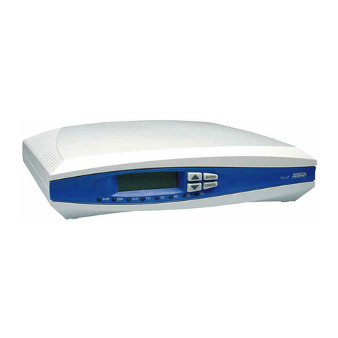
1.01 The Tellabs 263DC-1 (figure
1),
263DC-2,
and 263DC-3 Data Station Termination (DS1)
Systems interface
either
a2wire
or
a4wire data
set
with
a4wire transmission facility. All three
systems
are
compact, self-contained units that
provide data interface and
power
rectification/
regulation circuitry in an attractive enclosure that
can be wall mounted
or
placed on adesktop.
Power
for
these systems can be provided from
battery feed
or
sealing current derived from
the
units' simplex leads,
or
from an external source of
either
nominal 26Vac
or
-22
to
-56Vdc.
All three
systems feature prescription gain and loss in
the
receive channel, prescription loss in
the
transmit
the
263DC-2 and 263DC-3,
this
is in addition
to
channel, and manual
or
two-tone
loopback
In
any provided by
the
receive equalizer) for long
addition, both
the
263DC-2 and 263DC-3 provide sections of nonloaded cable. The facility-side trans-
prescription active equalization in
the
receive formers can also be optioned
to
derive normal
channel. All
three
units also include a20mA simplex leads,
to
provide an internal source of
sealing current source
to
provide sealing current sealing current
to
the
facility,
or
to
provide areturn
for
the
4wire
facility. path for sealing current applied at
the
far
end
of
Note:
Throughout the rest
of
this practice, the term
the
facility. (The
263DC
must be powered from an
2630C
refers to
all
three OST systems unless external source when
the
sealing-current source
otherwise
indicated. option is selected.)
1.02
In
the
event that this practice section is re- 1.05 On
the
station side,
the
263DC
can be
issued,
the
reason for reissue will be stated in this optioned
to
interface either a2wire
or
a4wire
paragraph. modem. In
either
mode,
the
station-side port(s) pro-
1.03 The
263DC
provides from
-24
to
+24dB
of vides capacitively-coupled, balanced, 600-ohm
gain in
the
receive channel and from 0
to
24dB
of terminating impedance.
loss in
the
transmit channel. Transmission levels in 1.06 The
263DC
provides loopback of
the
facility
both channels are prescription-set in 0.1dB incre- for testing and troubleshooting. The loopback func-
ments via DIP switches. The maximum input and tion can be activated either remotely by transmis-
output
level of each channel is
+5dBm.
While
the
sion of a2713Hz tone
or
locally via alocal loop-
263DC-1 provides no amplitude equalization,
the
back lead. When activated remotely,
the
263DC
263DC-2 and 263DC-3 both contain active pre- can be optioned
to
restore normal operation upon
scription equalizers in
their
receive paths. The receipt of asecond loopback
tone
or
automatically
263DC-2's equalizer is slope-type, providing up
to
at
the
end of a20-minute timeout period (receipt of
7.5dB of gain at
2804Hz
(re 1004Hz) in switch- asecond tone before
the
expiration
of
this
timeout
selectable 0.5dB increments. The 263DC-3's equal- period will also restore normal operation). The
izer is aslope/bump-type equivalent to the Western
263DC
system provides equal-level loopback with
Electric modei 309B. switch-selectable gain of 8
or
16dB in
the
loop-
1.04 Transformers· at both facility-side ports back path.
(receive
output
and transmit input) can be switch 1.07
Other
standard features
of
the
263DC
optioned
for
balanced 1200-, 600-,
or
150-ohm System include two 310-type
test
jacks and five
terminating impedance. The 150-ohm option pro- status-Indicating LEDs. The
test
jacks are opening-
vides approximately
2dB
of slope equalization (for type and face
the
DST system at
the
receive output
page
1

practice section 81263DC-1/81263DC-2/81263DC-3
and
transmit input
ports.
Four
of
the
LEDs
are
visible with
the
unit's cover in place. Ayellow
power
on LED lights when
power
is applied
to
the
unit. A
red loopback LED lights when
the
loopback cir-
cuitry
is activated. Two
other
yellow LEOs are
labeled data in and data out; these LEOs light
when data is present in
the
receive and transmit
channels, respectively. Afourth yellow LED located
on
the
unit's printed circuit board lights when
the
internal sealing current source
is
active and seal-
ing current is flowing.
One
optional feature is avail-
able on
the
263DC: apair of gas-tube lightning
protectors for
the
facility-side ports (Tellabs part
number
2630
L2).
1.08 The
263DC
can be powered remotely
(facility-powered) by sealing current
or
battery feed
applied at
the
far end
of
the
facility,
or
can be
powered locally by an external source
of
either
nominal 26Vac
or
-22
to
-56Vdc.
When facility-
powered,
the
263DC
derives its operating voltage
from
the
facility via its simplex leads. The
263DC
requires nominal 20mA sealing current
or
56Vdc
maximum battery feed
for
facility powered opera-
tion. The 263DC's internal sealing current source
cannot be used when the system
is
facility-powered.
When powered from an external source,
the
263DC
requires 18
to
28Vac
or
-22
to
-56Vdc
input. The nominal 26Vac can be supplied from a
commercial 120Vac, 60Hz outlet through use of a
Tellabs
8015
Transformer, which can be ordered at
the
same
time
as
the
263DC. The
263DC
con-
sumes amaximum of
30mA
of current under
normal operating conditions.
1.09 The 263DC is aself-contained DST system
housed in aplastic enclosure with aremovable
cover. Designed primarily for wall mounting,
the
263DC
is also equipped with rubber feet for desk-
top
placement. Ahole in
the
bottom
of
the
cover
(when wall mounted) allows access
to
the
unit for
external connections. Connections
to
the
facility
and
power
source are made at a17-position screw-
terminal strip. Connections
to
the
data
station are
made
to
the
terminal strip
or
to
amodular phone
jack
(similar
to
USOC RJ11C).
1.10 The 263DC can be equipped with
two
optional gas-tube lightning protectors for
the
facility-side ports (Tellabs part
number
2630
L2).
When
the
gas tubes are used,
the
PROT GND pin
on
TB1
must be
connected
to
earth ground for
proper protection from lightning strikes.
2.
application
2.01 The
263DC
DST System is used in applica-
tions
where
adata station communicates with
other
data stations
or
acentral processor unit
(CPU)
over
voice-grade
telephone
facilities. The
unit provides
the
necessary level coordination and
impedance matching
to
interface
the
modem
portion of
either
a4wire
or
2wire data
set
with a
4wire facility. If
the
data station is provided by the
customer,
the
263DC
acts as an interconnect
device,
providing end-termination
of
the
telco
facility.
Loopback
circuitry on
the
263DC
allows
either local (ground) activation
or
remote (two-tone)
activation of facility loopback, with switch-selectable
loopback-path gain of 8
or
16dB. The 263DC-2 and
263DC-3 versions of
the
system provide receive-
channel equalization. All
three
versions can supply
sealing current
to
the
facility.
2.02 Level coordination between
the
station and
the
facility is provided
independently
in each
channel of
the
263DC.
The
receive channel pro-
vides up
to
24dB of prescription gain
or
loss in
0.1dB increments, and
the
transmit channel pro-
vides up
to
24dB
of prescription loss, also in
0.1
dB
increments. The output levels
of
the
two
channels
are controlled by
the
transmit level and receive
level DIP switches (S13 and S19, respectively).
Adjacent
to
each DIP switch position is
the
value,
in
dB, of that switch position. These values are
cumulative;
the
total
amount
of gain
or
loss intro-
duced
into achannel is
the
sum of
that
channel's
DIP-switch positions set
to
in.
The maximum
input
and output level of both channels is
+5dBm.
These
level ranges allow
the
DST system
to
easily accom-
modate
the
-3
receive TLP (transmission level
point) and
+13
transmit TLP (assuming a
-13dBm
OTLP)
required by most modems.
2.03 Adata in and adata
out
LED on
the
cover
of
the
system light when data is present in
the
receive and transmit channels, respectively. The
level
detectors
that
drive
the
LEOs respond
to
data
levels
greater
than
-25dBm.
2.04 Both
the
263DC-2 and 263DC-3 provide
active prescription post-equalization of
the
facility
in
their
receive channels. The 263DC-2 uses a
slope-type amplitude equalizer
to
provide up
to
7.5dB
of
equalized gain at
2804Hz
(re 1004Hz) in
discrete 0.5dB increments. The frequency response
of
the
263DC-2's receive equalizer is
shown
graph-
ically in figure 2and in tabular form in
table
1.
The
263DC-3's equalizer is functionally equivalent
to
the
Western Electric model
309B
Prescription
Equalizer.
In
addition
to
providing slope-type
amplitude equalization,
the
263DC-3
provides
bump-type equalization with variable height and
bandwidth settings. Figures 3and 4
show
the
typical response curves for
the
263DC-3's equalizer
in
the
slope mode; figure 3shows
the
curves
for
loaded cable and figure 4shows the curves for non-
loaded cable. Table 2gives
the
1004Hz
reference
levels for figures 3and 4
for
various settings of
the
slope switch. Figures 5and 6
show
the
typical
response curves
for
the
263DC-3's equalizer in
the
bump mode; figure 5shows
the
curves represent-
ing various height settings versus awide bandwidth
setting and figure 6shows
the
curves represent-
ing various height settings versus anarrow band-
width setting. Table 3gives
the
1004Hz
reference
levels for figures 5and
6.
The equalization functions
of both
the
263DC-2 and 263DC-3 are controlled
by
DIP switches.
page 2

practice section
81263DC-1/81263DC-2/81263DC-3
7
:>dH
MAXIMUM
4KHZ
4KHZ
3KHZ
2KHZ
1KHZ
-2
table
2.
Equalized gam (m dB)
at
1004Hz
lor
263DC-3 equalizer in
slope
mode
-2
FREQUENCV
fjgure
6.
Typical response curves
for
263DC-3
receive-channel
equaiizer
in
bump
mode,
BW
switch
=3
HTSETTINGS
10
,.
6
8
..
C
z•
;;:
C>
2
00
10
HTSElTlNGS
8
,.
12
6
10
..
8
C
z•
"6
C>
2•
2
00
figure
5.
Typical response curves
for
263DC-3
receive-channel
equalizer
in
bump
mode,
BW
switch
=14
slope
loaded/nonloaded
switch
switch setting
setting
NL
L
a
0.0 0.0
(slope
disabled)
10.4 1.4
20.9 2.6
31.4 3.7
41.8 4.7
52.3 5.5
62.8 6.3
73.4 7.2
83.7
7.8
94.2
8.4
10
4.6 9.0
11
5.0 9.5
12
5.4
10.0
13
5.8 10.5
14
6.2
11.0
15
6.6 11.4
o
~d8
MINIMUM
0',
;0
,;
00
"
30
O~,HJ
2S
INCHlMlNTS
"
2804H, 3kHz
FRFOUFNCY
FREQUENCY
table
1.
TYPIcal
receIve-channel slope
equalization for 263DC-2
JOOlil
figure
2.
Typical response curves for 263DC-2
receive-channel
equalizer
'004
HI
o
C>
-2
Z
~2
'::,.
-3
~6
~15
figure
3.
Typical response curves for 263DC-3
receive-channel
equalizer
in slope mode,
loaded
cable
figure 4. Typical response curves
for
263DC-3
receive-channel equalizer in stope mode, nonloaded cable
..
C
Z-1
~
.,
~
1--+''-------1
receive
equalizer equalized gain (in dB)
introduced
at va,ious frequencies
,witch
setting (dB
300Hz
400Hz
500Hz
800Hz
1004Hz
1500Hz
1800Hz
2500Hz 2804Hz
0
00 00
00
00
0.0
00
0.0
00
0.0
0;
-
0.23
-0,19
-
0.15
-0,06
00
+0.1~
'0.24
+043
+0.50
,
.0
-0,~2
042
-0,33
0.13
00
+0.32
-.-0,52
+0.93 +1,07
,
.5
0.75
-0,60
0,49
-0,18
00
+0.46
-+0.74
+1.33 +1.54
"
-100
-0.80
-0.64
-0,24
0.0 +0.61 +0,98
-+1.76
-.-2,04
'.5
-1,22
0.98
-0.78
0.29 0.0 +0,75 +1,20 12.15 +2,49
3.0
-1.50
-1.20 -0.95
-0,36
00
+0,90
'1.45 +2,60 +3.01
35
1.71
-1,37
-1.09
-0,41
00
+1.03 -.-1.65 +2,97 +3,45
'.0
2.02
-1.63
-1.29
-0,49
0.0 -+1.22 +1,95 +3.54 +4.12
"
-2,25
1.79
-142
-
0.53
0.0 +1.33 +2.14
13.90
+4.56
50
-249
-1,98
-1.57
-0,59
00
-'-1,47
t2.36
+4,32 -+5.08
5.5
-268
-2.14 -
1,69
-0.63
0.0
,1.58
+2,53
'4.67
+5,51
6.0
-2.89
-2.30
-181
-0.68
0.0 +1.69 -+2.72 +5.05 +5,99
65
3.07
-2.44
1.93
-0.72
00
+1.79
1287
+5.38
1641
"
-3.29
2.61
-2.05 -0.76
00
1189
+3.05 +5.76 +6.90
75
-3.45
-2.74
-2,15
-0,78
0.0 +1.98
+319
+6.06 -.-730
"
•12
10
8
6
•SLOPE
2
SETTINGS
2
•
0
Z0
"
~
-2
page 3

practice
section
81263DC-1/81263DC-2/81263DC-3
HT
switch
BW
switch
setting**
setting*
6 7 8 9
10
11
12 13 14 15
2
0.0
0.0
0.0 0.0
0.0 0.0 0.0
0.1 0.1
0.2
3
0.0 0.0 0.0 0.0
0.0
0.0
0.1 0.1 0.1
0.3
4
0.0 0.0 0.0 0.0 0.0
0.1 0.1 0.1
0.2
0.4
5
0.0 0.0 0.0
0.1
0.1 0.1 0.1
0.2 0.3 0.5
6
0.0
0.0
0.1 0.1
0.1 0.1
0.2
0.2
0.4
0.7
7
0.0
0.1
0.1 0.1
0.1
0.2 0.2
0.3 0.5 0.9
8
0.0
0.1
0.1 0.1
0.2 0.2
0.3
0.4
0.7
1.2
9
0.0
0.1
0.1
0.2 0.2
0.3 0.4 0.5 0.8
1.5
10
0.0
0.1
0.2
0.2 0.2
0.3 0.4 0.6
1.0
1.7
11
0.1
0.1
0.2
0.2
0.3 0.4 0.5 0.7
1.2
2.0
12
0.1
0.1
0.2
03
0.3 0.4 0.6 0.9
1.4
2.4
13
0.1
0.2
0.3 0.3 0.4 0.6 0.8
1.1
1.7
2.8
14
0.1
0.2
0.3 0.4 0.5
0.7
0.9
1.3
2.0
3.3
15
0.2
0.3
0.4
0.5
0.7
0.9
1.2
1.7
2.5
3.9
*HT
switch position adisables
bump
function.
HT
switch position 1introduces
0.1dB
of gain or less
at
1
kHz.
**BW switch positions athrough 5introduce
0.1dB
of
gain
or
less
at
1kHz
for
all
HT
seltings.
table
3.
Equalized gain at 1004Hz for
263DC-3
equalizer
in
bump mode
2.05 The transformers
at
the
facility-side ports
of
permitting
the
maintenance
responsibility involved
the
263DC
can be switch-optioned
for
1200-ohm in a
particular
case
of
trouble
to
be determined.
terminating
impedance to
interface
loaded cable, 2.09 The
263DC's
loopback
circuitry
can be
for
600
ohms
to
interface
nonloaded cable
or
car- activated either remotely by transmission
of
nominal
rier,
or
for
150
ohms
to
provide approximately
2dB
2713Hz
loopback
tone
from
the
far
end
of
the
facil-
of
equalization (in addition
to
any provided by
the
ity
or
locally by
grounding
the
system's loop
back
263DC-2's
or
263DC-3's receive equalizer)
for
long lead.
Loopback
will
not
occur
accidentally
because
sections
of
nonloaded cable
through
the
deliberate
of
power
failure. When loop
back
is activated,
the
impedance mismatch. Both facility-side transformers loop
back
(LB) relay operates,
disconnecting
the
on the 263DC are center-tapped
to
derive balanced station from the data circuit and looping the receive
simplex leads. path
back
to
the
transmit path. Additional
contacts
2.06 The station-side
ports
of
the
263DC
can be
of
the
LB
relay electrically
disable
the
data
station
optioned
to
interlace
either
4wire
or
2wire data via
the
263DC's
TEK5 and TEK6 leads. The foop-
sets. In
the
2wire mode, an
electronic
hybrid pro-
back
LED on
the
system's
cover
lights
to
indicate
vides
the
necessary
4wire
to
2wire
conversion.
that
loopback
is activated.
Both
the
2wire
and
4wire
ports
provide fixed, 2.10 Remote
loopback
is
accomplished
by plac-
capacitively-coupled 600-ohm terminating imped- ing a
2713Hz
tone
on
the
receive pair
of
the
ances
toward
the
station.
263DC
for
at
least 1.6
seconds
and
then
removing
2.07 An option switch on
the
263DC
selects
the
tone. The
263DC
initiates
loopback
only
upon
either
internal sealing current, external sealing cur-
the
removal
of
the
tone. This prevents accidental
rent,
or
normal simplex leads. In
the
SOURCE looping
of
other
than
the
intended
loopback
point
position,
the
center-tapped leads
of
the
facility-side on amultipoint circuil. The
threshold
of
the
loop-
transformers are
connected
to
anominal
20mA
back-tone-detection
circuit
is
-30dBm
as meas-
integral sealing
current
source. In
the
SINK
posi- ured
at
the
receive input porI. The
loopback
tone
tion,
these
leads are
connected
together
to
pro-
detector's
center
frequency
is
2713Hz
±0.20/0
with
vide ade path
for
sealing
current
applied
at
the
far
amaximum bandwidth
of
75Hz. Asignal-to-guard
end
of
the
4wire
facility. The
SX
position provides ratio
of
6dB
prevents
either
raw data signals
or
normal simplex-lead derivation. An LED on the harmonics of
those
signals from initiating loopback,
263DC's
printed circuit board lights
when
the
thus allowing
the
263DC
to
operate
in
circuits
internal sealing-current source
is
active and cur-
where
similar units
might
be
prone
to
false
rent is flowing. loopback. Aswitch option allows remote
loopback
2.08 The
263DC
DST System can serve as a
to
be
deactivated
by asecond
2713Hz
loopback
testing and
troubleshooting
device
through its
tone
of
O.7-second duration
or
longer
(removal
of
ability
to
isolate
the
facility from
the
station via
the
tone
is not necessary
to
deactivate
loopback),
loopback. The loopback feature allows
the
voice-
or
automatically
after
a
20-minute
timeout
period.
frequency
characteristics
of
the
facility
to
be tested
2.11
Local
loopback
is initiated by placing a
from aremote location
(e.g.,
the
serving
CO).
Loop-
ground
on
the
local loop
back
lead (LOC
LB
back
also allows
the
source
of
trouble
to
be local- terminal
of
TBI).
Loopback
is maintained until
the
ized
to
either
the
facility
or
the
data station, thus
ground
is removed.
page
4

practice section
81263DC-l/81263DC-2/81263DC-3
clears
the
unit's chassis. The cover is replaced by
reversing this procedure.
mounting
3.03 The 263DC
is
wall mounted via three screws
(not supplied) inserted
through
holes
in
the
base
plate
of
the
unit. A
template
for
positioning
the
screws is proVided
at
the
end
of
this practice. Four
rubber feet are supplied
for
desktop
placement.
installer
connections
3.04 Before making any
connections
to
the
263DC, ensure that
power
is
not
applied
to
the
unit.
Power
should be
connected
to
the
unit
only
after
all
other
installer
connections
are made and
after
the
unit is properly optioned.
3.05
Make
all
telco
connections
(facility-side
ports and simplex leads)
to
the
263DC at 17-position
terminal block TBI. The modem connections (station-
side
ports
and
data disable leads), however, can be
made
at
TB
I
or
via
the
modular
phone
jack
(similar
to
USOC
RJllC),
J3, supplied with
the
unit. Access
to both
TB
Iand
J3
is through
the
bottom
of
the
unit. Connections to
the
263DC are listed in table
4.
Note:
When the 263DC is
equipped
with the
optional
gas-tube lightning protectors, the PROT
GND terminal on TB1
should
be
connected
to a
separate earth
ground
to provide maximum light-
ning
protection.
connect:
toTBl
pin:
facility:
XMTOUTTIP
............
...........
..
.............
IT
XMT
OUT
RING.
........
,-
...
TR
RCV
IN
TIP
....
-
..........................
.....
....
RT
RCVINRING
..............................
........
RR
simplex leads:
SX
TRANSM
IT
..........
.. ..
....................
..SXT
SX
RECEiVE
......
.
.................
~R
data station:
XMT
IN
TIP/2WIRE
TIP
...............
DIT/2WIRE
TIP
(or
J3
pin
4)
XMT
IN
RING/2WIRE
RING
........
DTR/2WIRE
RING
(or
J3
pin
3)
RCV
OUT
TiP
........................
DRT
(or
J3
pin
2)
RCVOUTRING
.....................
ORR
(or
J3
pin
5)
DATA
SET
DISABLE
................
TEK5
(or
J3
pin
1)
DATA
SET
DISABLE
................
TEK6
(or
J3
pin
6)
power:
AC
OR
DC
INPUT
......
.......
.
....................
AC
INPUT
GROUND
..........
..................
CKTGND
EARTH
GROUND
.............
....
.......
PROTGND
(only when optional
gas
tube
lightning
protectors
are used)
loopback:
local loopback
......
.
......................
LOC
LB
3.
installation
inspection
3.01 The 263DC Data Station Termination System
should
be
visually
inspected
upon arrival
to
find
any
damage
incurred
during
shipment.
If
damage
is
noted, aclaim should immediately be filed with
the
carrier. If stored,
the
unit should be visually inspected table
4.
External
connections
to
263DC
again
prior
to
installation. 3.06
To
power
the
263DC
from alocal external
cover
removal
source
of
either
nominal 26Vac
or
-22
to
-56Vdc,
3.02
To
instali
the
263DC
System, its protective make
power
connections
to
the
AC
terminals of
plastic
cover
must be removed. The cover is held in
TB
I(polarity need
not
be
considered
in
either
place by a
single
captive
screw
in
the
bottom
of
the
case). If
the
Tellabs
8015
Transformer is used
to
unit. To remove
the
cover, loosen
the
screw and supply
the
required
ac
voltage,
connect
terminals I
swing
the
bottom
of
the
cover
up
and
out
until it and 3
of
the
8015
to
the
AC
terminals
of
TBI, and
page
5
2.12 Equal-level
loopback
is provided by an
amplifier
in
the
263DC's
loopback
path. This ampli-
fier can be switch-optioned
to
insert
either
8
or
16dB
of
gain
between
the
receive
channel
and
the
transmit
channel
when
the
loop
back circuitry is
activated. Thus, in adata circuit with
either
an 8
or
16dB
difference
between
the
receive and transmit
TLPs, a
test
signal transmitted from
the
far
end
of
the
facility
at
the
normal data transmission level will
be returned
at
the
normal receive level. In data cir-
cuits
with
aTLP differential
other
than
8
or
16dB,
the
gain inserted
into
the
loopback
path must be
considered
when
making transmission level tests.
(Please
note
that
this problem can be avoided by
setting
the
amplifier
for
8dB
and inserting an addi-
tional
8dB
of
attenuation
into
the
transmit channel
via
the
xmt
level
switches
while
testing is in
progress.)
2.1
3The
263DC
can be powered locally from
an
external
source
of
either
nominal 26Vac
or
-22
to
-56Vdc,
or
it can be
powered
remotely from de
applied at
the
far
end
of
the
facility and derived
from
the
facility by
the
263DC's
simplex leads. The
power source is selected by aswitch option that con-
nects
the
input
of
the
263DC's
power
rectification/
regulation circuitry
to
the
AC
terminals
of
TB
I
or
to
the
simplex
leads. When
powered
externally,
the
263DC
requires 18
to
26Vac input
at
7.5VA
or
-22
to
-56Vdc
input at 15mA minimum. The required ac
input can be supplied from acommercial 120Vac,
60Hz
grounded
outlet
by using aTellabs
8015
Transformer (ordered separately). When powered
remotely,
Le.,
facility-powered,
the
263DC
requires
aminimum
of
20mA
dc, which can be supplied by a
regulated sealing-current source
or
by
direct
bat-
tery
feed
to
the
4wire
loop.
To
ensure
proper
opera-
tion
of
the
263DC
when
it is facility-powered,
the
ioop
length
between
the
263DC
and
the
power
source
should
not
exceed
1000
ohms
for
sealing
current
or
2000
ohms
for
battery
feed. Also, when
powered
by
battery
feed,
the
voltage across
the
263DC's
simplex
leads must
not
exceed
56Vdc. Both
facility-powering
schemes
are
shown
in figure
7.
Note:
The 263DC's
integral
sealing
current
source
can be
used
only
when the
263DC
is
powered
externally.

practice section
81263DC-l/81263DC-2/81263DC-3
4WIRE
FACILITY
FAR-END
DST 263DC
((
RT [>
~
RCV
~
~
RCV
II
IN {
OU,
JJ
RR
FAC
NOMINAL
8AC
~
_-v
20mA POWER
EXT
PWR
*S17
RECTIFICATION/
MODEM
de
SEALING
CURRENT
AC C
REGULATION
"l
SOURCE
PWR
-
II
TT
-
~
XMT
{
<J
~
XMT
II
OUT
{
IN
JJ
TR
263DC/DC-2 line-powered
by
sealing current
4WIRE
FACILITY
FAR-END
DST 263DC
"RT
[>
~
"RCV {
~
RCV
."IN {
OUT
"
RR
FAC
MAXIMUM
...L
~
_-V
±56Vdc AC POWER
BATTERY
-EXTPWR*S17
RECTIFICATION/
MODEM
FEED AC C
REGULATION
""l
-BATT
PWR
-
II
-
TT
<J
~
XMT
oj
~
XMT
II
OUT
~
IN
"TR
263DC/DC-2
tine-powered by battery
feed
*517
mustbe
settothe
FAC
PWR position
for
facility
powering
of
the
263DC.
517
must be set to
the
EXT PWR position to
supply sealing current to the facility.
figure
7.
263DC
remote powering schemes
then plug
the
8015 into a
grounded
120Vac, 60Hz
outlet. When
the
263DC
is
facility-powered, con-
nect
aregulated source of 20mA sealing current
or
nominal 48Vdc battery across
the
facility at
the
far
end as shown in figure 7_Option switch S17 must
be set
to
the
proper
position
for
either
external
power
or
facility power; see paragraph 3.12. As
stated above, power
connections
to
the
263DC
should be made only
after
all
other
connections
are made and
after
the
unit
is
properly optioned.
optioning
3.07 Optioning
the
263DC
consists of selecting
the
facility-side impedance,
the
2wire
or
4wire data
set interface,
the
loopback path gain,
the
tone-
loopback
release option,
the
power
option, and
selecting external
or
internal sealing current
or
normal simplex-lead derivation. The locations of
the
option switches are shown in figure
8.
Table 5con-
tains a
brief
explanation of
the
functions and set-
tings of each option switch plus aconvenient
optioning checklist. The checklist can be filled
out
(by checking
the
appropriate box for each switch)
either
prior
to
installation
to
allow
for
prescription
optioning of the unit or as the unit is being optioned
to
provide arecord for
future
reference. Detailed
instructions
for
optioning
the
263DC
are provided
in
the
following paragraphs.
3.08 Switch
SII
selects balanced 1200-, 600-,
or 150-ohm impedance at
the
facility-side ports
(receive input and transmit output). Set S
11
to
the
1200, 600, or 150 position as required. Generally,
the
1200-ohm option is used
for
loaded cable,
the
600-ohm option is used
for
nonloaded cable
or
car-
rier, and
the
150-ohm option is used
to
provide a
small amount of slope equalization for long sections
of nonloaded cable through a
deliberate
imped-
ance mismatch.
3.09 Switch S14 selects
the
desired data-station
interface,
either
2wire
or
4wire.
Set
S14
to
the
2W
position
to
interface a2wire modem
or
to
the
4W
position
to
interface a4wire modem.
3.10 Position 1of switch S15
selects
the
amount
of gain inserted between
the
receive channel and
page
6

practice section
81263DC-1/81263DC-2/81263DC-3
figure
8.
263DC
option
sWItch locatIOns
table
5.
263DC
option
summary
and
checklist
the
transmit channel when
the
unit is in loopback
(see paragraph 2.12).
To
insert
8dB
01
gain into
the
loopback path, set S15-1
to
the
8position.
To
insert
16dB of gain into
the
loopback path, set
S15-1
to
the
16
position.
check-
function switch selections settings list
facility-side
S11
150
ohms
150
port
impedances
(rev
out
and
600
ohms
600
xmt
in)
1200
ohms
1200
data-station
S14
2wire
2W
interface
4wire
4W
loop
back-path
S15-1
adS
gain 6
gain
16dB
gain
16
tone
loopback
S15-3
normal
(two
OFF
release
tone)
timeout
TO
(20 minutes)
tone
loopback
S15-2
enabled
n
disable
disabled
OFF
facility
or
S17
facility FAC PWR
external
power
via
power
SX leads
external EXT PWR
power
sealing
current
S18
internal
SOURCE
sealing-
current
source
de
return
SINK
path
for
far-end
source
normal
SX
simplex
leads
3.11 Position 3of S
15
selects
the
tone-Ioopback
release option. For normal two-tone operation
(Ioopback released by second loopback
tone
only),
set S
15-3
to
the OFF position. For timeout operation
(Ioopback released automatically
after
20
minutes
unless asecond tone is received prior
to
that
time),
set S15-3
to
the
TO
(on) position. Position
201
S15
disables the tone loopback circuit. For normal opera-
tion (tone loopback enabled) set S15-2
to
the
IT
(on)
position.
11
tone loopback is not desired, setS15-2
to
the
OFF position.
In
either
case, loopback can
still be activated locally via
the
local ioopback lead.
3.12 Switch S17 selects
either
facility
power
or
external power.
To
power
the
263DC
from sealing
current
or
battery feed via
the
simplex leads, set
S17
to
the
FAC
PWR
position.
To
power
the
263DC
from an external source of nominal 26Vac
or
of
-22
to
-56Vdc,
set S17
to
the
EXT
PWR
position.
Note:
The
263DC
must
be
powered
from an
external source when the 20mA sealing current
source is used.
3.13 Switch
SIB
selects
the
desired sealing cur-
rent option.
To
supply 20mA
of
sealing current
to
the
facility from
the
263DC's internal current
source, set S18
to
the
SOURCE position.
To
pro-
vide areturn path for sealing current supplied from
the
far
end
of
the
facility, set S18
to
the
SINK posi-
tion. If normal simplex lead derivation is desired,
set
SIB
to
the
SX position.
Note:
The
263DC's integral sealing current source
can
only
be used when the 263DC is powered from
an external source.
alignment
3.14 Alignment
01
all
three
versions of
the
263DC
consists of setting
the
transmit and receive
transmission levels and, for
the
263DC-2 and
263DC-3 only, setting the receive-channel amplitude
equalization if required. After all
options
on
the
unit
are selected,
two
methods of
alignment
are avail-
able: prescription
or
direct measurement (non-
prescription). With
the
prescription method,
the
unit's alignment switches are set according
to
the
specifications on
the
circuit layout record
or
on a
computer
printout.
In
cases where
the
information
supplied by
the
CLR
or
printout is inadequate
or
unavailable, it is necessary
to
perform
the
non-
prescription alignment procedure. The procedure
for prescription alignment of
the
263DC's transmit
and receive transmission level is given in para-
graph 3.15;
the
non-prescription alignment pro-
cedure is given in paragraphs 3.19 and 3.20 (long
form) and in figure 9(condensed form). The pre-
scription and non-prescription alignment procedures
for
the
receive-channel equalizer on
the
263DC-2
are given in paragraphs 3.16 and 3.21, respectively.
The prescription alignment procedure
for
the
263DC-3's receive-channel equalizer is given in
paragraph 3.17; information on non-prescription
alignment
01
the
263DC-3's equalizer is provided in
paragraph 3.22.
Note:
To
place the 263DC into loopback for test-
ing,
either
transmit a2713Hz tone
burst
at
alevel
of
page 7
o
"~'"
.
OFF
TT
OFF
TO
o
LOOP
BO~
DATA
o
DATA
o
POWE~
o

practice section 81263DC-1
/81263DC-2/81263DC-3
515
16~8
OFF
TT
OFF
TO
1
Refer
to
the
CLR
and
determine
the
following:
facility
port
impedances, re-
Quired
receive
output
level,
and
transmit
input
level.
Ensure
that
811 (facility
port
impedance) is
set
correctly. Then pro-
ceed
to
step
2and
perform
the
alignment
procedures
in
numeric
order. The para·
graphs
referenced
in
the
procedure
headings
provide
a
more
detailed
ex-
planation
of
that
specific
procedure.
o
LOOP
BACK
o
DATA
IN
o
DATA
OUT
o
POWER
ON
o
GN~L5
.1 ~
.2
!!.
M
.4
~
@+~'I
~
12
B!
C6»~·.I-"
_IN
o
00
FAC
50:~~~
~
rjlt
150600
1200
~EXT
~
...
518
PWR
I~-
I
~
V1~t
::R
YQ
RR
10
CKT
V2~
~
~~D
Y
\y
SXT
®®
~~r.
4W
+- +-
<9
ORR
~OO
(Qj
(Q]
~
~~;
2W
RCV
OUT
I~~~
0TEK5
o
TEK6
~
0AC
oAC
J3_
~~~7,T
Receive
Level
(paragraph
3.19)
2
Arrange
the
receive
portion
of
the
TMS
for
600~ohm
terminated
measure-
ment
and
connect
it
to
the
RCVOUTjack
(XMT
IN/2W
jack
for
2wire
operation).
3
Have
the
far
end
transmit
1004Hz
test
tone
at
the
level
specified
on
the
CLR. Measure the received level.
4Ifthespecified receive level is higher
than themeasured level, set513-1 tothe
GNposition. If
the
specified level is
lower
than the measured level,
set
813·1
lathe
LS
position.
Then
set
the
rev
level
(813-2
through
813-9)
switches
in
the
proper
combination
to
achieve
the
specified
output
level.
Transmit
Level
(paragraph
3.20)
5
Arrange
the
transmit
portion
of
the
TMS
(terminated
at
600
ohms)
for
1004Hz
tone
output
at
the
CLR- speci-
fied
level,
and
connect
it
to
the
XMT
IN/
2Wjack.
6Have
the
far
end
measure
and re-
port
the
received
level. Then
set
the
xmt
level (819)
switches
in
the
proper
com·
bination
to
achieve
the
specified
level
at
the
far
end.
Receive
Equalization
(263DC·2
only;
see
paragraphs3.17
and
3.22
for
the
263DC-3)
(paragraph
3.21)
7
Connect
the
receive
portion
of
a
properlyterminatedTMS
tothe
RCVOUT
jack
(X
MT
I
N/2
WIRE
iack
for2wireopera-
tion). Have
the
far
end
send
1004Hz
and
2804Hz
test
tones
at
the
CLR-specified
level.
Measure
and
record
these
levels.
8
Subtract
the
2804Hz
level from
the
1004Hz
level.
9
Set
to
in
the
proper
combination
of
equalization
switches
on
the
equalizer
subassembly
that
most
closely
approx-
imates
the
amount
arrived
at
in
step
8.
figure 9.
Condensed
non-prescription
alignment
procedures
30dBm
or
higher
for
at
least 1.6-seconds
and
then switches to achieve the required levels. The specific
remove the tone (remote loopback),
or
apply
aamount
of
loss
or
gain (in dB)
introduced
by
each
ground to the local loopback lead.
To
restore normal DIP-switch position is indicated on
the
switch body
operation,
either
transmit a
second
tone burst for
at
adjacent
to
the
switch position. These switch posi-
least 0.7
second
or
remove the
ground
from the tions are cumulative;
the
total
amount
of flat loss
or
local
loopback
lead. gain introduced into achannel is
the
sum of that
prescription
transmit
and
receive
level
channel's DIP-switch positions set
to
in. Switch set-
adjustment
(263DC-1,
-2, -3) tings and achecklist for prescription level adjust-
3.15
To
adjust
the
transmit and receive levels on ment are provided in table
6.
the
263DC
via
the
prescription method, proceed as
263DC-2
prescription
receive
equalizer
tollows: From
the
CLR, determine
whether
gain
or
alignment
loss
is
required in
the
receive channel and set
the
3.16
To
adjust
the
receive equalization on
the
GN/L5
switch (513-1)
to
the
appropriate position 263DC-2 via
the
prescription method, proceed as
(L5
or
GN). Next, determine (from
the
CLR) the follows: From
the
CLR,
determine
the
amount
of
amount of loss
or
gain required in
the
receive chan- equalized gain required at
2804Hz
(re 1004Hz).
nel and
the
amount
of loss required in
the
transmit Equalization is introduced into
the
receive channel
channel. Then set to in
the
proper
combination of via
the
equalizer DIP switch on
the
equalizer sub-
transmit levei (519) and receive level (513) DIP assembly. The specific
amount
of equalized gain at
page
8

practice
section
81263DC-1
/81263DC-2/81263DC-3
table
8.
263DC-2
rounded
equalizer
SWitch
settings
263DC-3's receive equalizer consists
of
entering
the
pertinent
data into acomputer-controlled cir-
cuit design system
that
provides a
printout
specify-
ing
the
required equalizer switch settings. The
BW
and HT switches,
or
the
slope and loaded/nonloaded
switches
are then
set
as directed. The 263DC-3's
receive equalizer can also be aligned by determin-
ing
the
facility characteristics from
the
CLR and
then
setting
the
receive equalizer
switches
as indi-
cated in Tellabs practice
section
819908B
or
Bell
System Practice (BSP)
section
332-912-222. These
practices contain extensive listings of various facility
characteristics (including
combinations
thereof)
and
the
equalizer switch
settings
required
to
com-
pensate
for
these. The 263DC-3's equalizer switch
sellings
and achecklist
for
prescription equalizer
alignment
are given in
table
7.
post-alignment
testing
3.18
After
the
transmission levels and receive
equalization are set, it may be desirable
to
confirm
the
results via end-to-end tests.
Where
computer-
controlled
test
equipment
is used, a
subsequent
printout will verify
the
alignment results. Any devia-
tion from
the
required levels can
then
be adjusted
via
the
appropriate switches. If computer-controlled
test
equipment
is
not
available,
the
alignment
results can be confirmed
by
performing
the
mea-
surements
in
the
condensed
test
procedures
in
figure
9.
non-prescription
receive·
level
adjustment
(263DC-l,
-2, -3)
3.19
To
adjust
the
receive level
of
the
263DC
when prescription level
settings
are not given in
the
CLR
or
when
the
given
settings
do
not
produce
adequate
results, proceed as follows:
A.
Ensure
that
no
receive level DIP-switch posi-
tions are set
to
in. Also
ensure
that
the
facility-
side port impedance switch (SI1)
is
set correctly.
B.
Arrange
the
receive
portion
of
atransmission
measuring set (TMS)
for
600-ohm
terminated
measurement and
connect
it
to
the
ReV
OUT
jack
(XMT
IN/2Wfor
2wire
operation). Have
the
far end send 1004Hz test tone at
the
specified
level.
2804Hz
(re 1004Hz) introduced via each DIP-switch
position
is
indicated on
the
printed
circuit board
next
to
the
switch position. These switch positions
are cumulative;
the
total
amount
of
equalized gain
(0
to
7.5dB)
introduced
is
the
sum
of
those DIP-
switch
positions
that
are
set
to
in. The 263DC-2's
receive equalizer switch
settings
for
prescription
equalizer
alignment
and a
checklist
are given in
table
7.
Because
the
required
amount
of
equaliza-
tion
given in
the
CLR may be specified
to
the
nearest
0.1
dB
while
the
equalization switch is ar-
ranged in 0.5dB increments,
table
8gives
the
rounded switch sellings
fo
the equalizer's full range.
function
switch
settings(in dB) checklist
rev loss
S13-1
LS
or
gain
GN
rev level
S13-2
.1
through
.2
S13-9
.4
.8
1.5
3
6
12
xmt
level
S19-1
.1
through
.2
S19-8
.4
.8
1.5
3
6
12
table
6.
263
DC level
alignment
switches
and
checklist
DSTunit
function
switch
settings
checklist
263DC-2 receive slope
S1
0.5
equalization
1
gain at 2
2804Hz 4
(re 1004Hz)
263DC-3 loaded/non-
S1-1
NL
loaded cable L
slope
S1-2
1
through 2
S1-5
4
8
height
S2-1
1
through 2
S2-4
4
8
bandwidth
S2-5
1
through 2
S2-8
4
8
table
7.
263DC-2
and
263DC-3
receive
equalization
switches
and
checklist
263DC·3
prescription
receive
equalizer
alignment
3.17
Because
the
263DC-3's receive equalizer
switch
settings
are
totally
dependent
upon
the
characteristics
(e.g.,
cable
gauge
and length,
loaded
or
nonloaded, etc.) of
the
facility
to
which
the
unit
is connected, it is recommended
that
the
equalizer
be aligned via
the
prescription method
only. In most cases, prescription alignment of
the
page
9
1000Hz·2804Hz
difference
0.0
to
0.2d8
0.3
to
0.7d8
0.8
to
1.2d8
1.3
to
1.7dB
1.8
to
2.2dB
2.3
to
2.7d8
2.8
to
3.2dB
3.3
to
3.7dB
3.8
to
4.2dB
4.3
to
4.7dB
4.8
to
5.2dB
5.3
to
5.7dB
5.8
to
6.2dB
6.3
to
6.7dB
6.8
to 7.2d8
7.3
to
7.7dB
amount
of
equalized
gain
required
O.OdB
0.5d8
1.0dB
1.5dB
2.0dB
2.5dB
3.0d8
3.5dB
4.0dB
4.5dB
5.0dB
5.5dB
6.0dB
6.5dB
70d8
7.5dB

practice section 81263DC-1/81263DC-2/81263DC-3
C.
Now
have
the
far end send
2804Hz
test
tone at
the
level specified on
the
CLR. Measure and
record
the
received
2804Hz
level.
Subtract
the
2804Hz
level from
the
1004Hz
level recorded
in step
B.
D.
Set
to
in that combination of equalizer DIP
switch positionswhich approximates as closely as
possibie
the
measured difference (see table
8).
263DC-3
non-prescription
receive
equalization
adjustment
3.22 For anon-prescription
alignment
procedure
for
the
263DC-3's receive equalizer, please refer
to
BSP 332-912-221.
4.
circuit
description
4.01
This circuit description is
intended
to
famil-
iarize you with
the
263DC
Data Station Termination
System
for
engineering and application purposes
only. Attempts
to
troubleshoot
the
unit internally
are not recommended and may void
your
warranty.
Troubleshooting procedures should be limited
to
those prescribed in section 7of
this
practice. Refer
to
the
263DC
block
diagram, section 5
of
this
prac-
tice, while reading this circuit description.
4.02 The unit's
power
supply consists of afull-
wave bridge rectifier, acapacitor
input
filter, and a
series voltage regulator. The full-wave bridge rectifier
allows
the
unit
to
be powered from
either
ac
or
de
input voltage. The capacitor input filter provides
isolation from ac signals present on
the
line, and,
when ac
power
is used, eliminates
60Hz
interfer-
ence from
the
signal path. The series voltage regu-
lator is used
to
derive astable de voltage for
the
internal circuitry.
4.03 Transformers at the facility-side ports (receive
input and transmit output) are
tapped
to
provide
switch-selectable 1200-, 600-,
or
150-ohm termi-
nating impedance. Asilicon voltage-transient sup-
pressor on
the
secondary
side
of each
transformer
limits transient potentials
to
asafe level and pro-
vides surge protection. Both transformers are
center-tapped
to
derive balanced simplex leads. A
20mA current source provides an internal source of
nominal 20mA sealing current. The 20mA current
source can be switch-optioned
to
provide sealing
current
to
the
facility via
the
unit's simplex leads,
to
provide areturn path
for
sealing
current
supplied at
the far end of the facility,
or
to
derive normal simplex
leads. Aseal
curr
LED on
the
unit lights when
the
internal 20mA current source is
selected
and cur-
rent is flowing.
4.04 The station side of
the
263DC
can be op-
tioned
to
interface either a2wire
or
4wire
data
station as selected by switch S14. An
electronic
hybrid circuit provides
the
necessary 2wire-to-
4wire conversion in
the
2wire mode.
4.05 Levels between
the
facility and
the
data
station are coordinated by
the
receive
amplifier
and
the
receive-level-control circuit. DIP
switches
in
the
receive-level-control circuit introduce controlled
feedback
into
the
receive amplifier circuitry
to
pro-
page 10
C.
If
the
level measuredat
the
RCVOUT(orXMT
IN/
2
W)
jack
is
the
sameas
that
specifiedon
the
CLR,
proceed
to
the
transmit level adjustment pro-
cedure
(paragraph 3.20). If
the
measured level is
lower than
the
specified level, set
the
GN/LS
switch(SI3-1)
tothe
GN position; if
the
measured
level is higher than
the
specified level, set S13-1
to
the
LS position. Then set
to
in
that
combination
of receive level DIP switch positions which equals
the
required
amount
of gain
or
loss
(i.e.,
the
dif-
ference between
the
specified level and
the
measured level).
Note:
The
amount
of
gain
or
loss introduced by
each position
of
the receive level switch is indicated
on the switch body. These switch positions are
cumulative; the total
amount
of
gain
or
loss intro-
duced
is the sum
of
those switch positions set to
in.
non-prescription
transmit-level
adjustment
(263DC-1,
-2, -3)
3.20
To
adjust
the
transmit level of
the
263DC
when prescription level settings are not given in
the
CLR
or
when
the
given settings
do
not pro-
duce adequate results, proceed as follows:
A.
Ensure
that
no transmit level DIP-switch posi-
tions
are
set
to
in. Also ensure
that
the
facility-
side port impedance switch
(SII)
is set correctly.
B.
Arrange
the
transmit portion of aTMS (properly
terminated at
600
ohms)
to
output
1004Hz
toneatOdBm
(or
other
datalevel specified by
the
CLR), and
connect
it
to
the
XMT
IN/2W
jack.
C.
Have personnel at
the
far
end
measure and
report
the
received ievel;
the
difference between
the
measured level and
the
specified level is
the
amount
of loss required in
the
transmit
channel of
the
DST unit.
Set
to
in
that
combi-
nationoftransmit
level(SI9)
DIPswitch
positions
which equal the required amount of attenuation.
Note:
The
amount
of
loss introduced
by
each
position
of
the transmit level switch
is
indicated on
the switch body. These switch positions are cumula-
tive; the total
amount
of
gain
or
loss introduced is
the sum
of
those switch positions set to
in.
263DC-2
non-prescription
receive
equalization
adjustment
3.21
To
determine
the
need for receive-channel
equalization
(I.e.,
post-equalization at
the
local end
of
the
4wire facility) and
to
make
the
required
adjustments when
the
263DC-2 is used, proceed
as follows:
A.
Ensure
that
none of
the
four equalizer DIP-
switch positions are set
to
in. Also ensure that
the
facility-side port impedance switch
(SII)
is
set correctly.
B.
Arrange
the
receive portion of aTMS for 600-
ohm terminated measurement and connect it
to
the
RCVOUTjack(XMT
IN/2
Wfor
2wire
opera-
tion). Have
the
far end send
1004Hz
test
tone
at
the
level specified on
the
CLR. Verify
the
pres-
ence
of test
tone
and record
the
measured
level.

practice
section
81263DC-l
/81263DC-2/81263DC-3
envelope delay distortion
less than 100 microseconds,
400
to 3000Hz
peak/average ratio
greaterthan 98
I
receive
channel
I
level range
o
to
24dB
of
gain
or
loss in switch selectable 0.1dB
increments,
with
gain or loss selected via switch
option
input impedance
150ohms ±15%, 600 ohms ±10%, or
1200
ohms
±10%,
balanced, switchable
total harmonic distortion
1%
maximum, 300
to
4000Hz
2630C-2
equalization
up
to
7.5dB
of
active slope equalization
at
2804Hz
(re 1004Hz) in switch-selectable0.5dB increments
2630C-3
equalization
slope/bump equalizer for loaded or nonloaded cable
-equivalent
to
Western Electric 30gB
-30dBm.
Aminimum
6dB
guard
band prevents
remote
loopback
activation
by
other
than
the
in-
tended
signal. Local
loopback
is
deactivated
by
removing the ground from the
LOC
LB
lead. Remote
loop
back
is deactivated in
either
of
two
ways: upon
receipt
of
asecond
2713Hz
tone
burst
of
0.7
second
or
longer, or automatically after a20-minute
timeout
period. The method
of
remote
loopback
de-
activation is selected via switch option. When
the
timeout
method
is selected,
loopback
can still be
deactivated by transmission
of
a
second
2713Hz
tone
before
the
timeout
period expires. An option
switch is also available
to
disable
the
remote-Ioop-
back
function
completely
when
desired.
4.12 Aloopback amplifier in
the
loopback
path
can be switch-optioned
to
provide
either
8
or
16dB
of
gain
between
the
receive
and
transmit
channels
when
the
unit
is in
the
loopback
mode. In circuits
with
either
an 8
or
16dB
differential
between
the
receive and transmit TLPs, this feature allows a
test
signal received at
the
normal data level
to
be re-
turned
to
the
remote location
at
the
same
level as
in normal operation.
specifications continued on page
13
specifications
noise
10dBrnCO maximum
maximum input level
+5dBm
maximum output level
+5dBm
6.
vide
up
to
24dB
of
gain or loss in
the
receive
channel
in
O.ldB
increments.
One
of
the
DIP switch
positions determines whether gain
or
loss is inserted
by
the
receive amplifier.
4.06
Both
the
263DC-2 and 263DC-3 provide
active post-equalization
of
the
facility via integral
prescription
amplitude
equalizers in
their
receive
channels. The 263DC-2's receive equalizer is
slope-type, providing
up
to
7.5dB
of
equalized gain
at
2804Hz
(re 1004Hz) in discrete 0.5dB increments.
The
263DC-3's
receive equalizer is functionally
equivalent
to
the
Western Electric model
309B
Prescription Equalizer. In addition
to
providing
slope-type equalization,
the
263DC-3 provides bump-
type equalization with variable height and bandwidth
settings. The equalization
functions
of
both
the
263DC-2
and
the
263DC-3
are controlled by DIP
switches
on
the
receive equalizer subassemblies.
4.07 The receive level
detector
responds
to
the
presence
of
data in
the
receive channel
at
levels
greater
than
-25dBm
by lighting
the
data in LED.
The location
of
the
receive level
detector
in
the
circuit-following
the
receive
amplitier
and receive-
level-control circuit and, on
the
263DC-2 and
263DC-3, the receive
equalizer-makes
it avaluable
troubleshooting
aid
because
it provides a
check
on
virtually all active circuitry in
the
receive channel.
4.08 Level coordination
between
the
data sta-
tion
and
the
facility is provided by
the
transmit
amplifier
and
the
transmit-level-control circuit. A
five-step
attenuator
in
the
transmit-level-control cir-
cuit provides
up
to
24dB
of
flat loss in
0.1
dB incre-
ments. This loss is inserted
into
the
transmit
channel
via an eight-position
01
Pswitch.
4.09 The transmit level
detector
performs
the
same
functions
for
the
transmit
channel as
the
receive level
detector
does
for
the
receive channel,
responding
to
the
presence
of
data signals above
-25dBm
by lighting
the
data
out
LED. The transmit
level
detector
is similarly located at apoint in
the
circuit
where
it provides a
check
of
the
maximum
amount
of
active transmit-channel circuitry.
4.10
The
loopback
control
circuitry provides
the
detection,
timing, and logic
functions
for
loopback
operation
of
the
263DC. The
loopback
circuitry can
be activated
either
locally via
ground
or
remotely
via
2713Hz
tone
(see paragraph 4.11). When loop-
back
is activated by
either
method,
the
loopback
(LB)
relay operates, opening
the
transmit
and re-
ceive
channels
toward
the
modem and
connecting
the
receive
channel
to
the
transmit channel. The
LB
relay also provides data-set-disable leads (TEK5
and TEK6)
to
disable
the
associated data
set
during
loopback. The
loopback
LED on
the
unit's cover
iights
when
the
unit is in loopback. I I
transmit
channel
4.11
Loopback
is
activated locally by applying .
ground
to
the
LOC
LB
lead. Remote
loopback
is level range
activated by application
of
a
2713Hz
tone
burst 1.6 0
to
24dB
of
loss in switch-selectable0.1dB
seconds
or
longer
in
duration; the
263DC
does
not
increments
go
into
loopback
until
the
tone
is removed. The maximum
input
level
threshold
of
the
tone-detection
circuitry
is fixed
at
+5dB
page
11


maximum
output
level
+5dB
output
impedance
150
ohms
±15%,
600
ohms ±10%,
or
1200
ohms
±10%,
balanced,
switchable
total
harmonic
distortion
1% maximum,
300
to
4000Hz
frequency
response
±0.5dB
re 1004Hz,
300
to
4000Hz
noise
10dBrnCO maximum
envelope delay
distortion
100
microseconds
maximum,
400
to
3000Hz
peak/average
ratio
greater
than
98
I
modem
interface
I
terminating
impedance
4wire:
600
ohms
±10%,
balanced,
capacitively
coupled,
both
channels
2wire:
600
ohms
±10%, balanced, capacitively
coupled
franshybrid loss (2wire
mode
only)
ERL
45dB
minimum
SRL
LO 35dB
minimum
SRL
HI 35dB
minimum
2wire return loss
ERL
28dB
minimum
SRL LO 21dB
minimum
SRL
HI 28dB
minimum
IlooPback
specifications
I
loopback-tone
frequency
detection
263DC
wililoopback
upon receipt
of
2713
±7Hz
tone
(subject
to
level and
timing
specifications listed
below)
263DC
will
not
loopback
upon receipt
of
tones
outside
the
range
of
2713
±37Hz.
loopback-tone
level
detection
threshold
-30dBm
loop
back
tone
duration
initiate:
1.6
seconds
minimum,
loopback
after
removal
of
tone
release:
0.9
±0.3
second
maximum,
release during
tone
tone
loopback
signa/-to-guard ratio
6dB
minimum,
18dB
maximum
optional
release
timeout
period
20
minutes
nominal aftertone-activation of
loopback
loopback level
either 16dB (equal level)
or
8dB
loopback-path gain,
switch
selectable
local
de
loopbaek
ground
to
operate,
2mA
maximum
I
common
specifications
I
lacility sealing current (Irom internal source)
20mA
nominal
practice
section
81263DC-1/81263DC-2/81263DC-3
input
power
facility power:
nominal
20mA
sealing
current
or
56Vdc battery feed (maximum)
external power: either 18
to
26Vac at 7.5VA (this can
be supplied from commercial 120Vac by using a
Tellabs 8015 Transformer)
or
-22
to
-56Vdc
at
30mA
(maximum
current comsumption)
operating environment
20'
to
130'F
(_7'
to
+54'C),
humidity
to
95%
(no condensation)
dimensions
height: 7.6 inches
(1
g.3cm)
width: 6.7 inches (17.Ocm)
depth:
2.0
inches (5.0cm)
weight
1
pound
14ounces (850 grams)
mounting
wall-mounted; rubber
feet
are
also provided for
desktop placement
7.
testing
and
troubleshooting
7.01 The testing
guide
checklist
in
this
section
may
be
used
to
assist in
the
installation, testing, or
troubleshooting
of
the
263DC-l,
263DC-2,
and
263DC-3
DST Systems. The
checklist
is
intended
as an
aid
in
the
localization
of
trouble
to
a
specilic
unit. If a
unit
is
suspected
of
being
defective, a
new
one
should
be
substituted
and
the
test
conducted
again. If
the
substitute
unit
operates
correctly,
the
original
unit
should
be
considered
defective
and
returned
to
Tellabs
for
repair
or
replacement.
We
strongly
recommend
that
no
internal
(component-
level)
testing
or
repairs be
attempted
on
the
unit.
Instead, a
malfunctioning
unit
should
be
returned
to
Tellabs
for
repair
or
replacement
as
directed
below.
Unauthorized
testing
or
repairs
may
void
the
unit's warranty. Also, if
the
unit
is
part
of
aregis-
tered
system,
unauthorized
repairs will
result
in
noncompliance
with
Part
68
of
the
FCC Rules
and
Regulations.
Note:
Warranty service does
not
include
removal
01
permanent
customer
markings
on the covers
01
Tellabs products,
although
an
attempt
will be made
to
do
so.
II
a
unit
must
be
marked
defective,
we
recommend
that
it
be done on a
piece
01
tape
or
on
aremovable stick-on label.
7.02 If a
situation
arises
that
is
not
covered
in
the
checklist,
contact
Tellabs
Customer
Service
as
follows
(telephone
numbers
are
given
below):
USA
customers:
Contact
Tellabs
Customer
Service
at
your
Teliabs
Regional
Office.
Canadian
customers:
Contact
Tellabs
Customer
Service
at
our
Canadian
headquarters
in Mississauga,
Ontario.
International
customers:
Contact
your
Tellabs
distributor.
US
central
region: (312)
969-8800
US
northeast
region: (412)
787-7860
US
southeast
region: (305)
645-5888
US
western
region:
(702)
827·3400
Canada: (416)
624-0052
page
13

practice
section
81263DC-1/81263DC-2/81263DC-3
7.03 If aunit is
diagnosed
as defective,
follow
the
replacement
procedure
in paragraph
7.04
when
acritical
service
outage
exists (e.g.,
when
asystem
or
acritical
circuit
is down and
no
spares are avail-
able). If
the
situation
is
not
critical, follow
the
repair
and
return
procedure
in paragraph 7.05.
replacement
7.04 To obtain a
replacement
unit,
notify
Tellabs
via letter or telephone (see addresses and numbers
below)
or
via TWX
(910-695-3530
in
the
USA,
610-492-4387
in Canada). Be
sure
to
provide all
relevant information,
including
the
8X263DC-X
part
number
that
indicates
the
issue
of
the
unit
in ques-
tion.
Upon
notification,
we
shall
ship
a
replacement
unit
to
you. If
the
unit
in
question
is in warranty,
the
replacement
will
be
shipped
at
no
charge.
Pack
the
defective
unit
in
the
replacement
unit's carton, sign
the
packing
slip
included
with
the
replacement, and
enclose
it
with
the
defective
unit (this is
your
return
authorization). Affix the preaddressed label provided
with
the
replacement
unit
to
the
carton
being
returned, and
ship
the
unit
prepaid
to
Tellabs.
repair
and
return
7.05 Return
the
defective
unit,
shipment
prepaid,
to
Tellabs (attn: repair and return).
in
the
USA: Tellabs, Inc.
4951
Indiana
Avenue
Lisle, Illinois
60532
telephone
(312)
969-8800
in Canada: Tellabs
Communications
Canada, Ltd.
1200
Aerowood Drive, Unit
39
Mississauga, Ontario,
Canada
L4W
2S7
telephone
(416)
624-0052
Enclose an explanation
of
the
unit's malfunction.
Follow
your
company's
standard
procedure
with
regard
to
administrative paperwork. Tellabs will
repair
the
unit
and
ship
it
back
to
you. It
the
unit
is
in warranty,
no
invoice will
be
issued.
test test
procedure
testing
guide
checklist
normal
results
if
normal
conditions
are
not
met,
verify:
transmit
level
transmit
channei
noise
receive
level
263DC-2
receive
equalization
Arrange
transmit
portion
of
TMS,
properly terminated
at
600
ohms,
for 1004Hz tone
at
OdBm.
Connect this signal to
XMT
IN
jack.
Arrange receive
portion
of
TMS
for terminated
measurement
at facility·side
port
impedance
selected
on
unit,
and
connect it to pins
TT
and
TR
on
TBI.
Vary
LOSS
set-
tings
over
their
entire
range.
Short
OTT
and
OTR leads
to-
gether
either
by
inserting
a
shorting plug into
XMT
IN
jack
or
by
strapping pins
OTT
and
OTR
on
TBI
together. Connect
noise
measuring
test
set
to
pins
TT
and
TR
on
TB1.
Vary
LOSS
settings over their entire range.
Remove
short
at xmt port. Ar-
range transmit portion
of
TMS
for 1004Hz tone
at
-10dBm.
Set
TMS
xmt
impedance to
match
unit's facility-side ports.
Connect
TMS
xmt
to pins
RT
and
RR
on
TB
1.
Arrange receive
portion
of
TMS
for
terminated
measurement
at
600
ohms
and
connect
it
to
RCV
OUT
jack.
Vary
GN/LS controls over their
entire
range.
Maintain
TMS
connections
as
described above. Transmit
2804Hz tone
from
TMS
and
set
equalizer
switches
to,in
one
at
atime.
Signal level
corresponds
to
loss
setting D.
Measured noise level is less
than
10dBrnCO
for all loss set-
tings D. Noise level follows
loss
setting D.
Signal level
corresponds
to
gain
or
loss setting
D.
Level
at
RCV
OUT
jack increases
to
7.5dB
above
1004Hz level
as
equalization
is
added
(O.5dB,
1.5dB,
3.5dB,
7.5dB)
D.
page
14
Power O. Wiring
D.
Proper
impedance setting D. 516 set
properly
0.511
set properly D.
Unit not
in
loopback D.
Xmt
in
port shorted D. Proper
termination impedances
D.
High
RF
environment
D.
Power
D.
Wiring
D.
Terminating
impedance
0.516
set properly
0.511
set properly D. Unit not
in
loopback
D.
Input level
at
2804Hz
same
as
1004Hz D. Terminating imped-
ances
correct
D.
Switch
S
11
set correctly
D.

practice
section
81263DC-1/81263DC-2/81263DC-3
if
normal
conditions
test
test
procedu
re
normal
result
are
not
met,
verify:
263DC-3
Maintain TMS connections as Level at RCV OUT
jack
varies Terminating
impedances
cor-
receive
described
in receive level test. with switch setting O. reet O. Switch
SII
set
cor-
equalization Transmit
3400Hz
tone
and
set
rectly
O.
slope,
HT,
and
BW
switches
to
various combinations.
receive
Short
rev in leads
together
by
Measured
noise is less than
Rev
in
port
shorted
O.
Proper
channel strapping
pinsRTandRRon
TBI
10dBrnCO for all gain/loss set- terminating impedance O. High
noise together.
Connect
noise mea- tings D.
Noise
level
follows
gain!
RF
environment
D.
suring test set
to
RCV OUT
jack
ioss settings O.
tone
Remove
short
at rev in port. Con·
Loopback
LED lights O. Mea-
Power
D. Wiring D.Transmitand
iooback
nect
rev
portion
ofTMS(properly
suredtransmitlevel
within
±1
dB
receive
channels
properly
terminated)
to
xmt
out
port, pins
of
level specified on CLR O. aligned O.
Loopback
tone
level
TT and
TR
on
TB
1.
Arrange
xmt
above-30dBm
O. SwitchS15-2
portion
of
TMS
for
2713Hz
out-
set
properly
O.
put
at CLR-specified loopback
tone
level at
proper
rev imped-
ance.
Connect
this
signal
to
rev
in port, pins RT and
RR
on
TBI;
after
2seconds
change
fre-
quency
to
1004Hz
and noteTMS
level reading.
tone
Maintain
test
connections
as
Loopback
LED
goes
out O. Xmt in and rev in
ports
not
loopback
described above and
change
shorted O.
release
frequency
to
2713Hz
for
1
second.
timeout
Place
the
DST unit in loopback
Loopback
LED
goes
outin
20
±1 S15-3 set
to
timeout position O.
loopback
as
instructed
in
tone
loopback
minute
D.
lest.
manual
Ground
LOC
LB. Arrange TMS
Loopback
LED iights O. Mea- Transmit and receive
channels
loopback
to
send
1004Hz
at specified
suredtransmit
levelwithin
±1
dB
properly
aligned O. Switch S15-
receive level and
at
proper
im- of specified level on CLR O. 1
set
properly
0.
pedance.
Connect
this
signal
to
rev in port, pins RT and
RR
on
TBt.
Arrange receive portion of
TMS for
appropriately
termi-
nated
measurement
and mea-
sure
level at
xmtout
port, pinsTT
and
TR
on TBI.
page
15

'irtellabs
TellabS Incorporated
4951 Indiana Avenue, Lisle, Illinois 60532
telephone (312) 969-8800
twx
910-695-3530

+~----
3=
w
wO:
..JO
o(/)
:::Co
....
ci'jj,
1-0:
~
o
o
~
J
o
N
....
cD
o
Il'l
~
-...J
+,----
!III
ii
E
!
Cl
l:
<=
l:
~
o
E
.
....
6
c
M
10
N
This manual suits for next models
3
Table of contents
Other Tellabs Network Hardware manuals
Tellabs
Tellabs FlexSym OLT-mini User manual
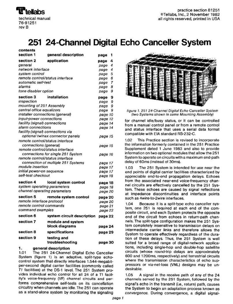
Tellabs
Tellabs 251 User manual
Tellabs
Tellabs FlexSym ONT205 User manual
Tellabs
Tellabs FlexSym OLT6 User manual
Tellabs
Tellabs 100 Series User manual
Tellabs
Tellabs 8820 MSR User guide
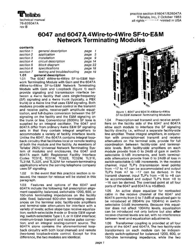
Tellabs
Tellabs 6047 User manual
Tellabs
Tellabs ONT180C User manual

Tellabs
Tellabs 7100 Operating and maintenance instructions

