Tellabs 251 User manual

7te11abs
technical
manual
76-81251
rev B
practice
section
81251
©Tellabs, Inc., 2
November
1982
all
ri9hts
reserved,
printed
in
USA
251
24-Channel Digital Echo Canceller System
figure
1.
251 24-Channel Digital Echo Canceller System
(two Systems shown
in
same
Mounting Assembly)
for channel idle/busy status,
or
it can be controlled
from amanual control panel
or
from aremote control
and status interface
that
uses aserial data format
compatible with EIA standard RS-232-C.
1.02 This Practice section is revised
to
incorporate
the information formerly contained
in
the 251 Practice
Supplement dated 1June 1983 and also to provide
information on
two
optional modules that allow the 251
System
to
operate on circuitswith amaximum end-path
delay of
60ms
(instead of30ms).
1.03 The 251 System is intended for use near
the
end points
of
digital carrier facilities characterized
by
appreciable end-to-end propagation delays. Echoes
from the associated near-end voice-frequency chan-
nel circuits are effectively cancelled by the 251 Sys-
tem. These echoes are caused
by
signal reflections
at impedance discontinuities and interface points
such as 4wire-to-2wire interfaces.
1.04 Because it is asplit-type
echo
canceller sys-
tem, one 251 is required at each end of the com-
posite circuit, and each System protects
the
opposite
end of the circuit from echoes in return-path chan-
nels. The split-type configuration makes
the
251 Sys-
tem completely insensitive
to
transmission delays on
intermediate carrier links and therefore allows
the
System
to
operate effectively regardless of
the
dura-
tion of these delays. Thus,
the
251 System is well
suited for abroad range of digital-network applica-
tions, including single-hop and double-hop satellite
circuits (whose round-trip delays are approximately
600
and 1200ms, respectively) and terrestrial circuits
where the transmission characteristics of
echo
sup-
pressors
or
via-net-Ioss (VNL) designs may be un-
desirable.
page
16
page
15
page
15
page
30
page 17
page 17
page 17
page
18
page
18
page
18
page 20
page
20
page 20
page
21
page 22
page
22
page
24
page
29
page
1
page
4
page 4
page 4
page 5
page 6
page 7
page 8
page 9
page
9
page 9
page 9
page 9
page 10
page
12
page
14
page
14
general
description
application
section
8
section
9
contents
section
1
section
2
general
network
interface
system
control
remote
control/status
interface
automatic
self-test
alarms
tone disabler option
section
3
installation
inspection
mounting
of
251 Assembly
central
office
equalizers
installer connections (general)
input-power
connections
facility (signal) connections
alarm connections
facility(signal) connections via
optional
twinax
connector
panels
remote
control/status
interface
connections
(general)
remote
control/status
interface
connections for single 251 System
remote
control/status
interface
connection
of
multiple 251 Systems
module insertion
initial power-on sequence
self-test
checkout
section
4
local
system
control
system operating parameters
channel
operating parameters
section
5
remote
system
control
remote interface
protocol
remote
control
commands
command
examples
section
6
system
circuit
description
section
7
module
and
system
block
diagrams
specifications
testing
and
trOUbleshooting
1.
general
description
1.01 The 251 24-Channel Digital Echo Canceller
System (figure
1)
is an adaptive, split-type echo-
control system
that
directly interfaces 1.544-megabit-
per-second digital carrier facilities (commonly called
TI
facilities) at the
DS-1
level. The 251 System pro-
vides individual echo control for all
24
of
a
T1
facil- 1.05 Asignal
in
the receive path of
any
of the
24
ity's voice-frequency
(VF)
channel circuits and per- channels served by the 251 System, followed by
the
forms comprehensive self-tests on its cancellation signal's echo in the transmit
(I.e.,
return) path, causes
circuitry
when
channels are idle. The 251 can operate the System
to
begin an adaptation process known as
as astand-alone system by monitoring
the
signaling convergence. During convergence, adigital signal-
page 1

practice
section
81251
processing
circuit
called a
convolution
processor
(one of which is provided for each channel) constructs
and stores in memory amathematical model of
the
channel's near-end transmission path (terminating
set and
interconnecting
link), and uses this model
to
compute
an
echo
estimate
for
the
channel. This echo
estimate
is then subtracted from
the
transmit-path
signal
to
actually remove
the
echo
from
the
signal.
1.06 When
the
transmit-path signal consists of both
echo (from
the
far-end speaker) and near-end speech,
the
251 System removes only
the
echo
signal, leav-
ing
the
speech
signal
intact
for
transmission toward
the
distant
end. Thus, parties
at
both
ends
can
talk
simultaneously (this is known as futJ-duplex speech
or
doubletalk)
without
the
choppiness
or
lockout
prob-
lems characteristic of
echo
suppressors. When only
the
far-end
party
is talking (one party
talking
is known
as
single
talk),
the
transmit signal consists entirely of
echo, which
the
251 System removes by subtracting
the
echo
estimate from
the
echo
signal. Any residual
echo, which is normally avery small amount (typically,
less than
-40dBmO),
is removed by an integral resid-
ual suppressor.
1.07 Convergence, the process of initially adapting
to
anear-end
echo
path, usually
takes
less than
200ms
(about two
or
three
syllables of speech), de-
pending upon
the
receive-path (far-end speech) signal
level. The 251 System can
adapt
to any near-end
path
with
aminimum
echo
return loss (ERL)
of
6dB
and amaximum end-path echo delay of
either
30ms
or
60ms, depending upon module selection. After con-
vergence,
the
251 System
continues
to
monitor
the
echo-delayand ERL characteristics ofthe near-end path.
During periodsof singletalk,
the
convolution processor
repeatedly updates its mathematical model to match
theseobservedcharacteristics. Thus,
any
change in
the
near-end path, such as aline being switched, will result
in anew end-path model
to
accommodate
the
changed
echo characteristics.
As
aresult, after achieving con-
vergence,
the
251 System performs
echo
cancellation
continuously, keeping
the
transmit path free of
echo
for
the
duration of
the
call.
1.08 Compact in size, an
entire
251 System com-
prisesonlysixTellabsType16 modules(five
modules
ifa
tone
disabler is
not
desired) and aprewired mounting
assembly, as shown in figure
2.
Each of
these
System
components is described briefly below.
1.09 The
6953
Echo
Canceller
Power
Supply
and
Alarm
Module
derives regulated
power
for
all of
the
System's digital logic circuits from filtered, ground-
referenced
-44
to
-56Vdc
(nominal
-48Vdc)
input.
In addition,
the
6953
provides local minor alarm indi-
cations (via front-panel LED's) as well as relay opera-
tion
for
remote major
and
minor alarm indications
when faults of various types
(e.g.,
loss of power) occur.
These alarm indications can be manually
terminated
by depressing afront-panel
afarm
cutoff
pushbutton.
Fusing
for
the
System's input
power
is provided by a
11
13-ampere GMT-type fuse
conveniently
located
on
the
module's
front
panel.
1.10 The
6952
Echo
Canceller
Network
Interface
Module,
which is used in applications
where
maximum
end-path delays
do
not exceed 30ms, provides all re-
quired interfacingwith the
T1
line(at
the
DS-1
level) and
performs all System timing functions (clock generation,
framing, and synchronization). If transmit synchroniza-
tion is lostdue
to
aproblem with
the
transmit-input PCM
line, ared
transmit
focaf LED on
the
front
panel lights. If
synchronization is lost at the channel bankwhose signals
are incoming
tothe
251 System(in whichcase
the
trans-
mit-input line indicates abit-2 alarm), ayellow
transmit
remote
LED lights. Asecond pair
of
front-panel LED's
providesidentical indications
forthe
receivechannel.
In
addition,
the
6952
contains
the
System's integral auto-
matic self-test subsystem
for
rapid
detection
and
iso-
lation of most System faults. With this subsystem, idle
channels
are
routinelysubjected
to
atest
sequence
that
on!! 251 SI/stem
OCClJpiei
one PIe65t no1e
that
mod
...
~irroklg4lmen1
1
_·
~~~~~~~
h8If(~ixpod:jtion~}ofT811.ab~
-~~~~~~-,
r·-------~
o1MCOOd2S1 Syl"tam
in25'tASMI'TIbIl'
-~~~~~--1·1
251
MOI.mt~n9
A~bly
differs ffQm
that
of
first
251
SYUm1
6953 6955
6952
6954
6951 6951
6955
6952
6954
6951 6951
6953
pow."
wpply
toft.dnublllr
-,
000001
chan""'l u'lil
cl~lIMflJml
rOlll!-di~bhll
"""",,,
(:(In(rOI
(:~.af1nel \In~l
etllmnel
unll
POWlWNpply
lr.dallM1l
module
int
..
faca
interface
module module
module
inrvrface iflterl:8ce
modu"
module
and
alarm
module
Ii,
module
modu~e
IL
module
module
module
--
BOO
[8J88
·"
1'1
I:
l
~
I.,
0..-
........,'.
_
..
0-
~
..
.."
tnll1~mit
~
tflm5m~t
~
-""'"'
0-
olocal
)-.
olocal
0-
0-
o,ornor8
~t
o
~8n'I018
~I
0-
ClIt.atIIitOo.ol.allDO
-"'''''''
~
......
~~'""
~.,.,.jrn"alj
~r
-+amolcall
ea.mClJttllI
..!:... j
.~c.MIl
r8WI1'8
~
recvll/lil
I"'
olocal
I'e
Ojocal
-48'" ·"."
.""
".".
"
~
o"mote
..
~
a
ftmO~e
".".
" I
.....
" I
--
~
·
rJ
~
0
"ioA
_.
P.A.
7teIabs
YIeIabs
~
7teIabs
YIeIabs
YteIabs
'I'teIabs
'I'teIabs
'I'teIabs
'rteIabs
7teIabs
~
figure
2.
Front detail
of
typical 251 System (Note:
Two
Systems, each containing the optional
6955
module, are
shown
in
the same
251
Assemby:)
page 2

practice section 81251
1.17 External connections
to
the
T1
(DS-1) PCM
lines are normally made via wire-wrapping
to
terminal
blocks on the 251 Assembly's backplane. If desired,
however, the Assembly can be factory-equipped with
two
optional Tellabs 80-0121
Twinax
Connector
Panels
for concentric twinax connection of the
T1
(DS-1) PCM lines
to
the Assembly. Each panel con-
tains four twinax connectors (Trompeter BJ77-type)
and serves one of the two Systems the Assembly can
accommodate. These panels are mounted on the
Assembly backplane via the same standoff posts
that
secure the CO equalizers; spacers provide the neces-
sary clearance between the panels and the equalizers.
means of aspecial printed-circuit backplane. As a
result,
neither
external
connections
to
individual
modules nor intermodule
connections
need be made.
Terminals on the backplane are provided
for
input
power and facility input and
output
connections. Two
versions of the 251 Assembly are available:
the
251A,
which mounts in a19-inch relay rack, and
the
251
B,
which
mounts
in a23-inch relay rack. Each version
accommodates 12 modules (two complete 251 Sys-
tems)
and
occupies
four
mounting spaces
(7
vertical
inches) in astandard relay rack.
1.16 The 251 Assembly is normally supplied with
four Tellabs
80-5078
Central
Office
Equalizer
sub-
assemblies
(two
per
251
System) factory-installed on
its backplane.These subassemblies provide the proper
amount
of
attenuation
to
limit
the
251 System's
transmit-output and receive-output signals (6 volts
peak)
to
no more than 3volts
peak
at
the
DX-1
cross-
connect
frame when
150
feet
(46
meters)
or
less of
cable
connects
the
251
System
to
the
cross-connect
frame. For
longer
cable runs,
two
direct-replacement
subassemblies that each provide less attenuation than
the 80-5078 are available. The Tellabs
9927
CO
Equalizer
subassembly
is designed
for
cable runs of
150
to
450
feet
(46
to
137 meters), and
the
Tellabs
9928
CO
Equalizer
sUbassembly
is designed for
cable runs of
450
to
650
feet
(137
to
198
meters).
1.13 The
6951
Echo
Canceller
Channel
Unit
Module
contains 12 independent convolution pro-
cessors and
their
associated timing-control circuitry.
Used in applications where maximum end-path delays 1.18 Although research indicates
that
voice-band
do not exceed 30ms, the 6951 performs the actual data can be transmitted
through
echo
cancellers
echo
cancellation for 12 of the
T1
line's
24
channels.
without
degradation, the 251 System can, if desired,
Two 6951 modules are therefore required
in
every be equipped with an optional
6955
Echo
Canceller
251 System.
Tone
Disabler
Module.
This
module
is equivalent
to
tone
disablers used in
echo
suppressors and serves
1.14 The
6951A
Echo
Canceller
Channel
Unit
the entire
251
System, providing independent opera-
Module
is designed
for
use
in
place of the 6951 mod- tion
for
each
of
the
24
channels. Upon receipt of
ule in applications where maximum end-path delays nominal
2100Hz
digital disabling
tone
in any channel,
are as long as 60ms. While it is functionally similar to the
6955
causes all
echo
cancellation and residual-
the 6951, the
6951A
contains
24
convolution pro-
echo
suppression
to
cease
for
that
channel. Thus, the
cessors arranged
in
12 independent pal'rs, plus the,'r channel is rendered completely transparent; its trans-
associated timing and control circuitry. Each pair of
convolution processors serves 1of the
T1
line's
24
mit-input PCM signals are not processed
but
simply
inserted into the correct time slots in the transmit-
channels, with 1processor of apair handling end-path output PCM bit stream. DIP
switches
on
the
6955's
delays of 0
to
30ms
and
the
other
handling end-path
delays of
30
to
60ms. Thus, as is
true
of the 6951 front panel allow each channel
to
be indiVidually
optioned so
that
echo
cancellation and residual-echo
module, one 6951Aserves 12 channels and, therefore, suppression
are
disabled only while
2100Hz
tone
is
two
6951A's are required
per
251 System. present
or
are disabled from the time
2100Hz
tone
is
1.15 The 251
Mounting
Assembly
is aTellabs received until the end
of
the
call (even if
tone
is
Type
16
Mounting
Shelf
that
is internally prewired by removed prior
to
the end of
the
call).
page 3
verifies
proper
operation of
their
convolution pro-
cessors and associated circuitry critical
to
echo can-
cellation. Any faults discovered result
in
local alarm in-
dications via an LED display on the System's control
interfacemodule.Thosefaultconditions
that
disablethe
System entirely, and
those
that do not disable the Sys-
tem but require immediate attention nonetheless, also
initiate relay operation in the
6953
module for remote
alarm indications.
1.11
The
6952A
Echo
Canceller
Network
Inter-
face
Module
is used in place of the
6952
module
in
applications where maximum end-path delays are as
long as 60ms. The
6952A
differsfrom the
6952
only
in
certain aspects of its EPROM software that allow the
6952A
to
operate in conjunction with
the
6951A
Channel Unit Module (see below).
New
system auto-
matic-self-test values
in
the 6952A's EPROM software,
for
example, ensure rapid detection and isolation of
6951A
channel failures.
1.12 The microprocessor-based
6954
Echo
Can-
celler
Control
Interface
Module
controls
and moni-
tors avariety of System functions. A
complement
of
six pushbuttons, seven
indicator
LED's, and an LED
window
display on
the
6954's
front
panel allows con-
trol
and
status information
for
the
System as awhole
and
for
its individual channels and subsystems
to
be
displayed
upon
demand; major and minor System
alarm indications are displayed automatically.
In
addi-
tion,
these
pushbuttons and LED's simplify
the
task
of
conditioning
the
251 System for aparticular applica-
tion
by
allowing both System and individual-channel
operating
modes
to
be programmed into memory
from
the
module's
front
panel. This memory is non-
volatile,
i.e.,
it retains all stored information in the
event of a
power
loss. Also available via
the
6954's
front
panel is manual override of most automatic Sys-
tem
control
functions. See paragraphs 2.05 through
2.13
for
details.

practice
section
81251
2.
application
general
2.01 The 251 24-Channel Digital
Echo
Canceller
System is primarily intended
for
use on single-hop
and double-hop satellite circuits and long terrestrial
circuits with
T1
(DS-1)
end
links. In such long-delay
circuits, the operating characteristics
of
conventional
echo suppressors may be objectionable,
thus
neces-
sitating the use of
echo
cancellers instead. Actually,
while the superior performance
of
the
251 System is
most noticeable on long-delay links, its insensitivity
to
total intermediate delay makes it suitable
for
nearly
all applications involving digital carrier. The 251 Sys-
tem cancels
echo
by adapting
to
each near-end
echo
path it encounters, and it can adapt
to
any near-end
path with an echo return loss (ERL)
greater
than
6dB
and amaximum round-trip delay (measured between
the System's receive-output and transmit-input ports)
of either
30ms
or
60ms, depending upon module
selection.
2.02 Atypical application of
the
251 System is
shown
in
figure 3. The primary cause
of
echoes
re-
ceived at
the
far
end
(B)
is
the
4wire-to-2wire voice-
frequency
(VF)
interface,
i.e.,
the
terminating
set, at
the near end
(A).
Signal reflections at
this
interface
are heard as
echoes
in
the
corresponding
far-end
channel. Because it is asplit-type
echo
canceller,
the
251
System at
the
near
end
actually
protects
the
far-
end receive channels from echo, and the far-end 251
System likewise protects
the
near-end receive chan-
nels from echo. This split-type configuration provides
effective
echo
control regardless of
the
total
delay
on
the intermediate transmission links.
*
6954
Echo
Canceller
Control
Interface
Mod-
ule
(one required
per
251 System).
*
6955
Echo
Canceller
Tone
Disabler
Module
(one
per
251 System is optional).
*
Issue
2
6900A
Blank
Type
16
Module
(one
per
251
System is optional when
6955
is
not
used).
network
interface
2.03 The 251 System interfaces
the
digital net-
work
directly
at the
T1
(or DS-1) level and
thus
eliminates
the
need
for
per-channel echo-control
devices on
the
associated VF circuits. At
this
inter-
face level, both the transmit and
the
receive channel
of the 251 System accommodate multiplexed
input
signals
in
aserial stream at 1.544 megabits
per
second with segmented 1'-"255
companded
PCM
coding. (This is the
DS·1
or
bipolar alternate-mark-
inversion [AMI] signal format.)
2.04 The 251 System typically operates
in
con-
junction
with aD-type channel
bank
or
adigital toll
switch. In such applications,
the
251 System is nor-
mally located between a
DX-1
cross-connect frame
on
the
side toward
the
far
end
(i.e.,
the
satellite side)
and
another
DX-1
frame and
the
associated channel
bank
or
digital switch on the side toward
the
near
end
(i.e.,
the terrestrial side). An
arrangement
of
this
type
is shown in figure
4.
Cabling
between
a
DX-1
cross-
connect
frame and aD-type channel
bank
must be
page
4
1.19 For any 251 System that does not require the
optional
6955
module, the Issue 2version of the
6900A
Blank
Type
16
Module
(Tellabs part number
826900A), which is also optional, can be used in place
of the
6955
to fill the empty module position
in
the
251 Assembly. The
6900A
helps
to
keep foreign mat-
ter
out
of the Assembly and also gives the System a
more attractive appearance.
In
addition, the Issue 2
version of the
6900A
can be used
to
silence external
alarms caused by removal of the System's
6953
mod-
ule from the Assembly. When the Issue 2
6900A
is
inserted into the module position from which a
6953
has been removed, aprojection at the end of the
6900A's
"pseudo
printed circuit board" opens the cut-
through module
connector
at that module position.
This causes both major-alarm and minor-alarm indica-
tions
to
cease. This feature is valuabie not only during
testing but also during installation of 251 Systems
in
prewired bays, in which case unwanted alarms can
result from module positions not yet equipped.
1.20 For reference purposes, the 251-System com-
ponents described above are summarized as follows:
*
251A
Mountin9
Assembly.
Twelve module posi-
tions, 19-inchrackmounting,equippedwith printed-
circuit backplane. Houses two complete 251 Sys-
temsand isfactory-equipped withfour
80-5078
CO
Equalizer subassemblies(two per System).
*251 B
Mounting
Assembly.
Same as 251A except
23-inch rack mounting.
*
80-5078
CO
Equalizer
subassembly
for
less
than
150
feet
(46 meters) of cable. Standard
equipment factory-installed on
251
Assembly
(four
80-5078's
per
Assembly).
*
9927
CO
Equalizer
subassembly
for
150
to
450
feet (46
to
137 meters) of cable. Optional direct
replacement
for
80-5078.
*
9928
CO
Equalizer
subassembly
for
450
to
650
feet
(137
to
198
meters) of cable. Optional direct
replacement
for
80-5078.
*80-0121
Twinax
Connector
Panels for concen-
tric
twinax connection of
T1
(DS-1) PCM lines
to
251 Assembly. Optional, factory installed (two
per
Assembly).
*6951
Echo
Canceller
Channel
Unit
Module.
Serves 12 channels
in
applictions where max-
imum end-path delays do not exceed
30ms
(two
6951's required
per
251 System).
*6951A
Echo
Canceller
Channel
Unit
Module.
Takesthe place ofthe6951 andserves 12 channels
in
applications where maximum end-path delays
are as long as
60ms
(two 6951A's required
per
251 System).
*
6952
Echo
Canceller
Network
Interface
Mod-
ule. Used
in
applications where maximum end-
path delays do not exceed
30ms
(one required
per
251 System).
*
6952A
Echo
Canceller
Network
Interface
Mod-
ule. Takes the place of the
6952
in
applications
where maximum end-path delays are as long as
60ms
(one required per 251 System).
*
6953
Echo
Canceller
Power
Supply
and
Alarm
Module.
Operates from nominal
-48Vdc
input
(one
6953
required
per
251 System).

practice
section 81251
FAA
EHO(81
I\
\
XMT XMT
OUT
IN
251
XMTT1
LINE
24-CHAHNEil
ECHO
D3
CANC:ELLEfIt
CHANNEL
SYSTEM
BANK
OR
DlQITAL
SWITCH
RCVn
LINE B
I
SHORTiEND-PATH DIGITALCAARIER CIFlCUllS
NEAA·ENDVOICE·FREQUENCY
CIACUITS110F24CHANNEUit
\L-------------""DIG;;<;n
w
Al".nE1WO=ORvK
---'
r-
130mB
MAXI"'UM)
/
2WtRE
TERM
@HO
XMT
XMT
SET
PAnt
4WIA£
IN
F-1
XMTT1
LINE
2.,
24·C"AHHEL
'-
ECHO
CANCELLeR
DIGITAL
SYSTEM
WITlI6951A'll
lO
$WITCW
ANDIQS2A
SA
DATER
~
A
2WIRE
TERM
@HO
4WI'RE
SET
PAnt
I~cv
i::c
vr
RCVT1
LINE
OUT
I.
LONG
END-PAlH A)
~
(8Oms
MAXIMU".
/\
NEAR
END
(A)
figure
3.
Typical application
of
251 System
ROM
END
UITS
XMT
f-
IN
OUT
-
DS-'
..
251
24-CHANNEL
ECHO
OX-,
CANCELLER
DX-'
OR
SYSTEM OR
TO/F
DSX-' DSX-'
FAR-
X-CONN. X-CONN. CIRC
FRAME
FRAME
f-
RCVOUT
I
tRCV
IN
DS-'
XMT
DS-' (
)
OOTYPE
CHANNEL
BANK
OR
DIGITAL
SWITCH
-
..
TO/FROM
NEAR-END
CIRCUITS
2.06 The 251 System uses
the
basic
03-channel-
bank sequential channel-numbering scheme. With
this scheme,
the
channel
number
assigned
to
each of
the
24
T1-line (DS-1)
time
slots
is
the
same as
the
number of
the
time slot. Other types of channel banks,
however, use different channel-numbering schemes.
Table 1lists
the
channel-numbering
schemes
for
01 D
and
02
as well as
03
channel banks.
figure
4.
Physical
connection
of
251 System
done
with
22-gauge
or
heavier
shielded
cable. With programmed via
the
6954
include
(1)
selection
of
the
22-gauge
cable, maximum
permissible
distance
be- data
transfer
rate (see paragraph 4.04)
for
the
remote
tween
the
DX-1
cross-connect
frame and
the
251
control/status
interface port,
(2)
automatic
blanking
System, including intraframe cabling in
the
DX-1
of
the
channel
display
after
a1-minute timeout, (3)
frame, is
650
feet
(198 meters). Where
this
distance
assignment of aSystem
unit
number
for
multiple
restriction
cannot
be met, heavier
cable
should
be
daisy-chained Systems, and (4) selection of one
to
six
used. In
extreme
cases, an intraoffice span
(Le.,
an in-
consecutive
self-test failures before
generation
of an
traoffice
repeater
line) can
be
used. In all applica- alarm.
tions,
separate
input and
output
cables must be used
between
DX-1
frames and
the
251 System.
system control
2.05 All
internal
System
control
functions
originate
in,
and all externally derived System
control
functions
are
handled through,
the
6954
Control Interface Mod-
ule.
Pushbutton
switches and LED's on
the
6954's
front
panel (see figure 2) provide
the
means
for
pro-
gramming
both
System and individual-channel oper-
ating
parameters
(in effect, optioning
the
System for 2.07 For each of
the
251 System's
24
channels, a
its
particular
application). These
codes
are
stored in a
number
of
control
inputs can be
entered
externally
special nonvolatile memory
that
retains all stored in-
(Le.,
via
the
6954's
front panel
or
via aremote
control!
formation
even if
power
to
the
251 System fails. After
status
interface [see paragraphs 2.11 and 2.12])
to
the
desired operating parameters are programmed, override certain internal
control
functions
normally
the
6954's
push
buttons
and LED's can be used to performed by
the
6954
in response
to
information
display
the
status
of
these
parameters
at
any time. contained in
the
transmit-input bit stream. As is
true
Specifically,
the
channe'
LED
window
and advance of all user-programmed System parameters, the status
pushbutton
are used
to
select
and display
the
chan- of each externally
inputted
control
function
can be
nel number, and the five control
and
two status
LED's
displayed at any time after the function
is
initiated.
indicate
the
selected
channel's status. The five push- The external control inputs
that
can be
entered
for
buttons
associated
with
the
control
LED's are used
to
each channel individually
to
override internal
control
control
the
indicated
functions.
Options
that
can be functions are as follows:
page
5

practice
section
81251
to hold its current contents. The
channel's
echo-
cancellation circuitry
and
residual
suppressor
still
operate normally, but the channel's convolution
processor(s) is prevented from adapting
to
changes in the end path.
Note:
II
self-testing is taking
place
at
the time the
Hhold
input
is entered, self-test failure
occurs
and
the 6954's
test
fail LED
lights
because adap-
tation is disabled
by
the Hhold input.
remote
control/status
interface
2.11 The 251 System can, if desired, be
controlled
from aremote location via a
remote
control/status
interface that uses aserial data
format
compatible
with EtA standard RS-232-C. The 251 System itself is
data terminal equipment (DTE), and
the
signals it pro-
vides are suitable
for
serial interface
with
either
data
communication equipment (DGE) or,
if
anull-modem
adapter is provided, with other
DTE.
All channel-related
control functions and status indications available via
the
6954
module's front-panel
switches
and LED dis-
plays are also available via
the
remote
control/status
interface.
2.10 For details on local configuration and status-
monitoring via the
6954
module's
controls
and indica-
tors, refer
to
section 4
of
this
Practice,
local
system
control.
2.08 For each channel, additional status informa-
tion derived from the
6954
module's internal control
circuits can also be displayed at any time via the
6954's
status LED's. This information consists of the
follOWing:
A.
Channel's failure of self-test and subsequent re-
moval of the channel from service (status test fail
LED lighted).
B.
Channel's
echo
cancellation disabled
for
any
of
the following reasons (status bypass LED lighted):
(1)
The channel is bypassed.
(2) The Hreset control input is activated
for
the
channel.
(3)
The channel is idle (on-hook) and therefore
has been automatically placed in
the
self-test
mode.
(4)
Atone-generated data-disable condition is
detected by the
6955
module,thuscausing
the
6954
module
to
automatically
generate
an H
reset control input for the channel.
2.09 When operating as astand-alone unit,
the
251
System monitors the channel-associated signal-
ing in
the
frame-6 and frame-12 signaling bits of both
the transmit and receive digital lines
to
determine
the
busy/idle
status of each channel. If desired (or if
channel-associated signaling is not present),
the
channel busy/idle status can be provided
externally
through the remote
control/status
interface, typically
from aprocessor-controlled toll switch (see para-
graphs
2.11
through 2.13).
F.
E.
251-System and
basic
03-bank
sequential
THine
channel-number
010
channel-
02
channel-
(08-11 assignments number number
time
slot (preferred) assignment assignment
11 1
12
2 2 13
13
3 3 2 1
,,14
17
5535
6615
21
7 7 ,9
8 8 16 15
9 9 53
10 10 17 19
11 11
67
12 12 18 23
13
13
7
11
"14 19 14
15 15
8 2
16
16
20 18
17
17 96
18 18
21
22
19
19 10
10
20
20 22 16
21
21
11
,
22
22
23
20
23 23
12
8
24 24 24
24
table
1.
Channel-number assignments for T1-line
(OS-I) time slots
A.
Bypass.
When
the
bypass
input
is entered, can-
cellation is disabled; the channel is routed around
the processing circuits and placed
in
the
self-test
mode. Self-test failures cause the
6953's
minor-
alarm relay
to
operate and
minor
alarm LED
to
light and also cause the
6954's
test
fail LED
to
light. The bypass input also lights
the
6954's
control
bypass and status bypass LED's.
B.
Off
Hook.
When the
011
hook
input
is entered,
the
channel is placed in a
permanent
busy condi-
tion.
Continuous
echo cancellation takes place,
and self-testing is inhibited. Also, any existing test
fail and
minor
alarm indications
for
the channel
are cleared.
C.
Bypass
plus
Off
Hook.
When abypass and an
011
hook
input are entered simultaneously, the
channel is completely removed from service. It is
routed around
the
processing circuits,
and
the
test fail and
minor
alarm indications
for
the
channel are cleared and inhibited.
D.
Canceller
Only. When the canceller
only
input is
entered, the channel's residual suppressor is dis-
abled but its cancellation circuitry remains active.
Note:
If
self-testing is taking place
at
the time the
canceller
only
input
is entered, self-test failure
occurs
and
the 6954's test fail LED lights because
the residual
suppressor
is
checked
by
self-test.
HReset. When the Hreset input is entered, the H
register (which stores the mathematical model of
the end-path impluse response) is zeroed, effec-
tively disabling echo cancellation
for
the channel.
The
Hreset input also lights the
6954's
status by-
pass LED.
Note:
II
self-testing is taking
place
at
the time the
Hreset
input
is entered, self-test failure
occurs
and
the 6954's test fail LED lights because can- 2.12 Figure 5shows
four
possible
remote
control/
cellation is
disabled
by
the Hreset input. status interface configurations.
In
configuration a,
H
Hold.
When the H
hold
input is entered, up- the control
center
is close enough
to
the
251 System
dates are inhibited so that the Hregister is forced to allow a
direct
RS-232-C connection. The maximum
page 6

practice
section
81251
OCE
da'sy-chain
...--
~b-Ie
(see flgure
8;
251
SYSTEM
2
TERMINAL
OR
COMPUTER
IOTEI
OTE
d,aisyot::h8in
+---c",ble
('See
figure-
7)
r-------,
II
I I
I
TERMINAL
OR I
ICOMPUTER I
IOTEI
i--------l
I I
I I
I I
I I
I
TERMINAL
I
OR
ICOMPUTER I
IOTE)
II
I I
L_~TROL~~_~
+--..null modem
adapter
lsee figure til
standard
~S232C
eable
a.
b.
c.
1------1
I I
I
TERMINAL
I
OR
ICOMPUTER I
(OTEI
II
I I
L_~~CENTER_
~
251
Sy$lem
data
RS-232-C
nuU-modem Wiring
terminal
interface equipment
(OTE) (OTEf
25D 25D
signal connector connl;l!ctOf
s~gnal
pm
pin
FRAME
11
FRAM
GND GND
Jlrome
TXD
2ground 2
TXD
RXD
33
RXD
RTS
4
t:J
c4
RTS
CTS
55
CTS
GND
77
GND
OCD
8
ls.gna,
8
DCD
'='
ground
DTR
20
20
DTR
figure
5.
Four
remote
control/status
interface configurations
data
link
are used
to
link
the
251 System
to
acontrol
center
located beyond the range of adirect RS-232-C
connection.
In
configuration c, four
251
Systems are
interfaced
with
the
control
center
via a
OTE
daisy-
chain cable (figure
7).
As
in configuration
a;
the
range of
the
direct daisy-chained
connection
is
50
feet. In configuration d, the 251 Systems are inter-
faced
with
the
control
center
via a
OCE
daisy-chain
cable
(figure
8),
two
modems, and aprivate data link.
Contact
Tellabs' Applications Engineering Group
at
our
U.S.
or
Canadian headquarters
or
at
your
Tellabs
Regional Office
for
details on
other
special
interface
configurations.
2.13 For details on
the
remote
control/status
inter-
face protocol and on remote configuration and status-
monitoring procedures, refer
to
section
5of this Prac-
tice, remote system control.
automatic
self-test
2.14 The 251 System's self-test subsystem auto-
matically verifies proper operation of each channel's
convolution processor (and associated
support
cir-
cuits),
doubletalk
detector, and
update
control ci
r-
figure
6.
Null-modem wiring for connection to DTE cuits. The self-test
sequence
is
initiated
by
the
6954
recommended
range
for
a
direct
RS-232-C connec- Control Interface Module, which scans each channel
tion
is
50 feet. Anull-modem adapter, the wiring
of
at
regular 36ms intervals for on-hook/off-hook status.
which is shown in figure
6,
interfaces
the
251 Sys- On-hook (idle) channels are marked available
for
test,
tern
(OlE)
with
the
control-center
terminal or com- and this information is passed to
the
6952
or
6952A
puter.
In
configuration b, two modems and aprivate Network Interface Module, which contains
the
self-
page 7

practice
section
81251
251 System 1RTS
~
251
System 2
RTS
0
CTS CTS
Rxe
TXD
GND
oeD
OTR
Rxe
TXD
GNP
oeD
OTR 5
1 3 278
20
1 3 278
20
remote control male
center
(PTE)
-connectors -
pin no
.•
FRAME
GROUND
11
TXQ
2
Rxe 3
RTS 4:J
CTS 5
GNP
7
OeD 8
DTR
20
tfemale
251
System N(up
to
32) RTS 0
CTS
AXe
TXD
GND DCD OTR 5
13 2 78
20
I
connector
figure
7.
Daisy-chain
connection
of
multiple
251
Systems
to
DTE
251
System 1RTS
t:)
251
SyS1lml
2RTS
CJ
CTS CTS
Rxe
TXD
GND OCD OTR
Rxe
TXD GND DCD
OTR
5
1 3 278
20
1 3 278
20
modem
(DeE)
m
••
-
connectors-
pinno.~
FRAME
GROUND
1I
TXO
2I
t><:
Rxe
3
RTS 4
~
eSR 6
I--
GND
7
oeD
8
><
PTR
20 L.
4
251
System
N
(up
to
32)
RTS
CTS
RXO
TXD
GND
oCD
DTR
5
1327820
figure
8.
Daisy-chain connection
of
multiple
251
Sysfems to
DeE
test
circuitry
and performs the actual testing. The test-
ing sequence, which takes approximately
750
milli-
seconds
per
channel, is halted
for
any channel that
goes off-hook during testing, while on-hook channels
continue
under
test until
the
end of the test sequence.
Test results are reported
for
only those channels that
have undergone
the
entire test sequence. Any chan-
nel that repeatedly fails aself-test activates aminor
alarm (see paragraphs 2.15 and 2.16) and causes a
channel alarm code
to
appear
in
the LED display on
the
6954
module.
alarms
2.15 When fault conditions are
detected
by
the
251 System, they are automatically classified as
minor
or
major, depending upon
their
effect
on
the
System. Both classes of alarms result in similar alarm
indications: lighting
of
the sysfem alarms
minor
or
major
LED on
the
front panel
of
the
6953
Power Sup-
ply and Alarm Module and lighting of
the
channel
LED display (indicating
the
affected
channel) and ap-
propriate
status
LED's on
the
front
panel of
the
6954
Control
Interface
Module. In addition,
each
of
the
two
alarm classes has
two
dedicated
pairs
of
form-C relay
contacts, both
of
which provide aclosure
for
an ex-
ternal indication (audible, visible,
or
both) when an
alarm occurs.
2.16
Minor
alarms are
generated
upon failures
of
single channels.
In
addition
to
initiating
the
afore-
mentioned LED indications and minor-alarm relay-
contact operation, failure
of
asingle channel causes
the
251 System
to
bypass
that
channel
so
that trans-
mission can still take place over
the
channel, albeit
with possible echo.
page 8

2.17 Major alarms comprise
the
following:
A.
Loss of remote transmit or receive frame syn-
chronization (yellow transmit remote
or
receive
on
6952
or
6952A
module lighted). If frame syn-
chronization cannot be achieved in
3ms
or
less,
the aforementioned LED indications on the
6953
and
6954
modules are provided and major-alarm
relay-contact closure takes place. Also, the entire
251 System is bypassed so that transmission can
still take place over all
24
channels, albeit with
possible echo.
B.
Loss
of
remote transmit
or
receive frame syn-
chronization (yellow transmit remote
or
receive
remote LED on
6952
or
6952A
module lighted). If
remote frame synchronization cannot be achieved
in the amount of time allotted,
i.e.,
if abit-2 aiarm
from
the
channel
bank
on the transmit-input or
receive-input line is detected, the aforementioned
LED indications on the
6953
and
6954
modules
are provided and major-alarm relay-contact closure
takes place. Also, the entire 251 System is
by-
passed
so
that
transmission can still take
pi
ace
over all
24
channels, albeit with possibie echo.
C.
Failure of 251-Assembly
input
power, faiiure of
the
6953's
power supply,
or
biowing of the 6953's
input-power fuse. If input power
to
the
251
Assem-
bly fails, if the 6953's power supply fails entirely or
cannot maintain System power within its regulated
limits,
or
if
the
6953's
front-panel 1V3-ampere fuse
blows,
the
power
LED on
the
6953
goes
off and
major-alarm relay-contact ciosure takes place.
(No
other
LED indications are provided.)
D.
Failure of
the
6954's
microprocessor system. If
the
6954's
microprocessor system fails, the afore-
mentioned LED indications on the
6953
and
6954
modules are provided and major-alarm relay-con-
tact
closure takes place. Also, the entire 251 Sys-
tem is bypassed
so
that transmission can still
take place over all
24
channels, albeit with pos-
sible echo.
2.18 When
either
aminor
or
major alarm
not
caused
by
a
power
failure,
a
blown
fuse,
or
re-
moval
of
the
6953
from
its
module
position
occurs,
momentarily depressing the alarm
cutotf
pushbutton
on
the
6953's
front panel restores
the
corresponding
alarm relay
to
its normal state,
thereby
causing the
external alarm indications
to
cease. Aithough de-
pressing
the
6953's
alarm
cutoff
pushbutton clears
all external alarm indications, local alarm indications
(the lighted system alarms
major
or
minor
LED on the
6953
and
the
lighted LED display on
the
6954)
remain until the fault is cleared.
2.19 When
an
alarm caused by failure of input
power
to
the
251 Assembly, failure of the
6953's
power
supply, blowing of
the
6953's
input-powerfuse,
or
removal of the
6953
from its module position
occurs, the aiarm indications can only be cleared by
locating and correcting
the
problem.
tone
disabler
option
2.20 Should disabling of any of
the
251
System's
channels during voice-band data transmission be
deemed
necessary, the System can be equipped withpage 9
practice section 81251
an optional
6955
Echo Canceller Tone Disabler Mod-
ule. This single module serves
the
entire System, pro-
viding independent operation
for
each channel. Upon
detection in achannel of digital
2010
to
2240Hz
dis-
abling
tone
(at alevel greater than
-36dBmO)
in
either
or
both d'"ections of transmission, the module
disables that channel's echo-cancellation circuitry
and residual suppressor
so
that
the channel is com-
pletely transparent
to
all transmission. Aguard band
is used
to
prevent false operation of
the
6955
mod-
ule by
speech
signals. Three 8-position DIP switches
on the
6955's
front panel allow each channel
to
be
individually optioned so that disabling occurs only
while
tone
is present or so that disabling lasts from
the time
tone
is
detected
until the end
of
the call
(even if
tone
is removed
prior
to
the
end
of the call).
3.
installation
inspection
3.01 Each component of the 251 24-Channel Echo
CancellerSystem,
i.e.,
all five modules(six ifthe
6955
is
used) and the
251
Mounting Assembly, should bevisu-
ally inspected upon arrival
to
find possible damage in-
curred during shipment. If damage is noted, aclaim
should immediately be filed with
the
carrier. If stored,
both the modulesandthe assemblyshou
Id
beinspected
again prior
to
installation.
mounting
of
251
Assembly
3.02 The 251 AMountingAssemblymounts
in
astan-
dard 19-inchrelayrack, andthe251 B
Mounting
Assem-
bly mounts
in
astandard23-inchrelayrack. Each version
of
the
251 Assembly occupies 7inches of vertical rack
space. Ensure thatthe
251
Assembly is securelymount-
ed before proceeding to
central
office
equalizers and
installer connections below.
central
office
equalizers
3.03 The
251
Assembly is normallyshippedwith four
Tellabs80-5078Central OfficeEqualizersubassemblies
(one
for
the transmit
output
line and
one
for
the re-
ceive
output
line of each of the two Systemsthat the
Assembly can house) factory-installed on the Assem-
bly's backplane.
To
replace any of
these
equalizers
(e.g.,
if aTellabs
9927
CO Equalizer subassembly [for
150
to
450
feet
of cable between the System and the
DX-1
cross-connect frame) or aTellabs
9928
CO Equal-
izer subassembly [for more than
450
feet
of cable be-
tween the System and the
DX-1
cross-connect frame)
is to be used
in
place of an
80-5078
subassembly),
proceed as follows:
A.
Remove and save the two Phillips-head screws
that secure the subassembly to its standoff posts
on the backplane. (If your
251
Assembly is
equipped with optional Tellabs 80-0121 Twinax
Connector Panels, remove and save the
four
Phillips-head screws that secure the twinax con-
nector panel covering the subassembly to be
replaced. Then remove and save not only the
panel itself but also the four spacers between the
panel and the subassemblies below
it.)
B.
Unplug the subassembly
to
be replaced from its
five-pin
connector
(P4,
P5,
PIG, or
PI
I).
C.
Plug the new subassembly into the five-pin con-
nector.

practice
section
81251
and
two
25-pin
female
RS-232-C
connectors.
These
items
are
shown
in
figure
9,
and
all
mandatory
and
optional
connections
to
asingle 251 System
are
sum-
marized
in
table
2.
Detailed
wiring
instructions
and
a
complete
wiring
table
for
both
systems
in a251
Assembly
not
equ
ipped
with
twinax
connector
pan-
els
follow
in
paragraphs
3.07
through
3.09. If
your
251
Assembly is
equipped
with
twinax
connector
panels,
make
all
connections
except
facility
(signai)
connec-
tions
and cable-shield
connections
as
directed
in
paragraphs 3.07
through
3.09;
then
proceed
to
para-
graph
3.10.
Note:
Before
making
any
connections
to
the
251
Mounting
Assembly,
ensure
that
power
is
off
and
modutes are
removed.
Modules
shoutd
be
inserted
into
their
Assembly
positions
onty
after
all
wiring is
completed. For easy reference
during
the wiring
pro-
cedure, table 3lists each
individual
connection
(both
mandatory
and
optional)
for
each
of
the
two
251 Sys-
tems
that
can
be
housed
in a251 Assembly. Acheck-
list
in the table's
rightmost
column
can
be filled
out
mandatory
connections:
power
inputs:
-BAT
(-44
to -56Vdc, filtered,
positive
ground
referenced)
+GND (input ground
[OVdc))
T1
lines
(05-1
message
signals}(see
note
1):
ReV
IN T&R (receive input from far end)
ReV
OUT
T&R (receive
output
to near end)
XMT
IN T&R (transmit input from near
end)
XMT
OUT
T&R
(processed transmit output to far
end)
optional
connections:
power
inputs:
FRAME
GROUND
T1
lines
(05-1
message
signals)
(see note
1):
RCV
IN
SH
(receive input cable shield)
ReV
OUT
SH
(receive output cable shield)
XMT
IN
SH
(transmit input cable shield)
XMT
OUT
SH
(transmit output cable shield)
alarm
outputs:
MINOR ALARM (Two form-C sets
of
minor-alarm relay
contacts
are
available)
MAJOR ALARM (Two form-C sets
of
major-alarm relay
contacts
are
available.)
remote
control/status
interface
connections
(made
via
25-pin
o-subminiature
RS-232-CIV.24 connector)
(see
note
2):
FRAME
GROUND
TXD
(transmit data output)
RXD
(receive data input)
RTS
(request to
send)
CTS
(clear to
send)
GND
(signal ground)
DCD (data
carrier
detect)
DTR
(data terminal ready)
Note
1: These
connections
can be made
either
directly
to the
251-Assembly
backplane
via wire-wrapping or to an
optional
Teflabs 80-0121 Twinax
Connector
Panel via
appropriate
cables.
Note
2: The
251
System's
remote
control/status
interface sig-
nals are
compatible
with EIA
standard
RS-232-C
electrical
characteristicS
and
are thus suitable
for
serial
interface
with
data
communication
equipment.
D.
Secure
the
new
subassembly
to
its
standoff
posts
with
the
two
Phillips-head screws. (If
your
251
Assembly
is
equipped
with
twinax
connector
pan-
els,
replace
the
four
spacers
between
the
two
subassemblies
and
the
twinax
connector
panel
that
was
removed, reinstall
the
panel
over
the
subassemblies, and
secure
the
panel and sub-
assemblies
with
the
four
Phillips-head screws.)
installer
connections
(general)
3.04
Because
the
251
Assembly
is
prewired and
equipped
with aprinted-circuit backplane,
neither
ex-
ternal
connections
to
individual
modules
nor
intermod-
ule
connections
need
be made.
The
only
mandatory
external
connections
to
each 251
System
in a251
Assembly
are
as
follows:
A.
Eight
facility
(signal)
connections,
consisting
of
one
tip
and
one
ring
connection
for
each
of
the
four
inpul/output
cables
accessing
the
System.
Unless
the
251
Assembly
is
equipped
with op-
tional
twinax
connector
panels (see paragraph
3.10),
these
connections
are
made
via wire-
wrapping
to
four
clearly
labeled
three-pin
terminal
blocks
on
the
Assembly's backplane.
B.
Input
battery
and
ground
connections,
which
are
made
with
16AWG
or
heavier
wire
to
screw-type
terminals
on a
three-position
barrier
strip
on
the
Assembly's backplane.
3.05
Optional
external
connections
to
each 251
System
in a251
Assembly
comprise
the
following:
A.
One
cable-shield
connection
for
each
of
the
four
facility
(signal)
inpul/output
cables. Unless
the
251
Assembly
is
equipped
with
optional
twinax
connector
panels
(see
paragraph
3.10),
these
are
made
via
wire-wrapping
to
the
same
three-pin
ter-
minal
blocks
used
for
facility
(signal) connections.
B.
Input-power
frame
ground.
This
connection
is
made
with
16AWG
or
heavier
wire
to
the
same
three-position
barrier
strip
used
for
input
battery
and
ground
connections.
C.
Connections
for
external
minor-alarm indications.
These
connections
are
made
via
wire-wrapping
to
asix-pin
terminal
block
on
the
251 Assembly's
backplane.
(Two
sets
of
minor-alarm relay con-
tacts
are
provided,
and
three
pins
are
used
for
each
set.)
D.
Connections
for
external
major-alarm indications.
These
connections
are
made
via
wire-wrapping
to
asix-pin
terminal
block
on
the
251 Assembly's
backplane.
(Two
sets
of
major-alarm relay
con-
tacts
are
provided,
and
three
pins
are
used
for
each
set.)
E.
Remote
controllstatus
interface
connections.
These
connections
are
made
via a
25-pin
female
D-subminiature
connector
arranged
for
RS-232-C
serial
interface
and
located
on
the
251 Assem-
bly's backplane.
3.06
Because
the
251
Assembly
can
house
two
separate
and
independent
251 Systems,
the
Assem-
bly's
backplane
contains
two
input-power
barrier strips,
two
sets
of
wire-wrapping
terminal
blocks
for
facility
(signal), minor-alarm,
and
major-alarm
connections,
page
10
table
2.
Summary
of
mandatory
and
optional external
connections
to
251
System (made via
251-Assembly backplane)


practice
section
81251
(by checking the appropriate boxes) either prior to
wiring
to
indicate
the
required
connections
for apar-
ticular
application
or
as
wiring is
being
done
to
pro-
vide a
record
for
future reference.
input-power connections
3.07
Input-power
connections
to
each
251
System
in
the
251
Assembly
must
be
made
with
16AWG
or
heavier
wire.
The
screw
terminals
on
the
three-posi-
tion
input-power
barrier
strips
accept
16
to"
12AWG
wire
directly;
wire
terminated
in
appropriately
sized
spade
lugs
can
also
be
used.
Make
the
input-power
connections
to
the
251
Assembly
as
follows:
for righthand system
(as
viewed
from front
of
assembly):
A.
Connect
fiitered,
positive-ground-referenced
-44
to
-56Vdc
input
power
to
the
-BAT
terminal
on
barrier
strip. terminal
section
of
block, or terminal
or
pin check-
system system connection connector no. designation or no.
list
righthand power inputs input battery
(-44
P3
-BAT
(as
viewed
to
-56Vdc,
filtered,
from
front
positive ground referenced)
of
251
input ground (positive)
P3
+GND
Assembly)
frame
ground*
P3
FRAME
T1
lines
(D5-1
receive input tip
P7
RX IN T(TIP)
message signals) from
far
ring
P7
RX IN R(RING)
end
shield*
P7
RX IN
SH
(SHIELD)
receive
output
tip
P6
RX
OUT
T(TIP)
to
near
ring
P6
RX
OUT
R(RING)
end
shield
*
P6
RX
OUT
SH
(SHIELD)
transmit input tip
P8
TX
IN T(TIP)
from near ring
P8
TX
IN R(RING)
end
shield*
P8
TX
IN
SH
(SHIELD)
processed
tip
pg
TX
DUT
T(TIP)
transmit Qut-
ring
pg
TX
DUT
R(RING)
put
to
far end shield* pg
TX
OUT
SH
(SHIELD)
minor alarm first
set
of
normally Pl (upper MIN
NC
outputs relay con- dosed three
pins)
tacts* common MIN C
normally MIN NO
open
second
set
normally Pl (lower MIN
NC
of
relay
closed
three pins)
contacts* common
MINC
normally MIN
NO
open
major alarm first
set
of
normally
P2
(upper MAJ
NC
outputs relay con-
closed
three pins)
tacts
*common
MAJC
normally
MAJNO
open
second
set
normally
P2
(lower MAJ
NC
of relay
closed
three
pins)
contacts* common
MAJC
normally MAJ
NO
open
remote control/ FRAME GROUND 25-pin connector 1
status
inter-
TXD
(transmit data output) J15 (REMOTE 2I
face*t
RXD
(receive data input) CONTROL RS-232/ 3
pin
numbers on
RTS
(request
to
send)
V.24 DTE) 4connector.J15
CTS
(clear
to
send)
5listed
for
GND
(signal
ground) 7reference only
DCD
(data carrier detect) 8
DTR (data terminal readyI20
continued on next
page
table 3. Wiring table: external connections to
251
Assemblybackplane
tor
righthand
and
lefthand
251
Systems
in
Assembly
page
12

practice
section
81251
barrier
strip. terminal
section
of
block,
or
terminal
or
pin check-
system system connection connector no. designation or
no.
list
lefthand power inputs input battery
1-44
P18
-8AT
(as
viewed
to
-56Vdc,
filtered,
from front positive ground referenced)
of
251
input
ground (positive)
P18
+GND
Assembly) frame
ground*
P18
FRAME
T1
lines
IDS-1
receive
input
tip
P13
RX IN T(TIP)
message signals) from
far
ring
P13
RX IN R(RING)
end
shield
*
P13
RX IN
SH
(SHIELD)
receive output
tip
P12 RX OUT T(TIP)
to
near
ring
P12
RXOUT
R(RING)
end
shield"
P12
RXOUTSH
(SHIELD
transmit input
tip
P14
TX
IN T(TIP)
from
near
ring
P14
TX
IN R(RING)
end
shield*
P14
TX
IN
SH
(SHIELD)
processed
tip
P15
TX
OUT
T(TIP)
transmit Qut-
ring
P15
TX
OUT R(RING)
put
to
far
end shield*
P15
TX
OUT
SH
(SHIELD)
minor alarm first set
of
normally
P17
(upper MIN
NC
outputs relay con- closed three pins)
tacts*
common
MINC
normally MIN
NO
open
second set
normally
P17
(lower
MIN
NC
of
relay closed three pins)
contacts* common
MINC
normally
MIN
NO
open
major alarm first set
of
normally
P16 (upper MAJ
NC
outputs relay Con- closed three pins)
tacts* common MAJ C
normally
MAJNO
open
second set normally
P16
(lower
MAJNC
of
relay closed three pins)
contacts* common
MAJC
normally
MAJNO
open
remote control! FRAME GROUND 25·pin connector 1
status inter- TXD (transmit data output) J16 (REMOTE 2
face*t
RXD (receive data input) CONTROL RS-232/ 3pin numbers
on
RTS
(request
to
send)
V.24 DTE) 4connector J16
CTS
(clear
to
send)
5listed for
GND (signal ground) 7reference only
DCD
(data carrier detect) 8
DTR(data terminal ready) 20
*This connection or group
of
connections
is
optional.
tThe
251 System's remote control/status interface signals
are
compatible with EIA standard RS-232-C electrical character-
istics and are thus suitable for serial interface with data communication equipment (DCE).
table
3.
Wiring table:
external
connections
to 251 Assembly
backplane
for
righthand
and
iefthand
251 Systems in Assembly
page 13

practice
section
81251
barrier strip
P3
(located at
the
lower lelthand cor-
ner
of
the
assembly as viewed from
the
back).
B.
Connect
positive ground
to
the
+GND
terminal
on barrier strip
P3.
C.
Connect
optional frame
ground
(if used)
to
the
FRAME terminal on barrierstrip
P3.
for
lefthand
system
(as
viewed
from
front
of
assembly):
D.
Repeat steps Athrough C
but
make connections
to
barrier strip P18 (located at
the
lower
right-
hand
corner
of the assembly as viewed from
the
back) instead of
P3.
facility
(signal)
connections
(without
twinax
connector
panels)
3.08 For each
of
the
two
systems the 251 Assem-
bly can house, four three-pin terminal blocks are pro-
vided on
the
Assembly's backplane
for
connection
to
the
1.544Mbps, 100-ohm PCM lines.
Connections
be-
tween the Assembly and the
DX-1
cross-connect frame
should be made with 22AWG twisted-pair shielded
cable. Separate receive input, receive output, transmit
input, and transmit
output
cables are recommended.
If cables containing multiple twisted pairs with acom-
mon shield are used, ensure
that
the
transmit input
(TX
IN) and receive input (RX IN) pairs are
in
adif-
ferent cable than
the
transmit
output
(TX
OUT) and
receive
output
(RX OUT) pairs. This will prevent cross-
talk between the high-level
(3
to
6V peak) regenerated
output
signals from the system and the low-level (1.5
to
3V peak)
input
signals. Depending upon the CO
equalizers used (see paragraph 3.03), the maximum
permissible length of 22AWG cable between the As-
sembly and the
DX-1
cross-connect frame is
650
feet
(198 meters). If
this
distance restriction cannot
be met, heavier cable must be used. In extreme cases,
an intraoffice span
(i.e.,
an intraoffice repeater line)
can be used. Make
the
facility (signal) connections
(by wire-wrapping) as follows:
Note:
To
accommodate awide range
of
office in-
stal/ation methods, the
SHIELD
wire-wrapping pins on
PCM-line terminal blocks P6 through P9
and
P12
through P15 are provided as tie points only. These
pins are
not
connected to frame
ground
(as
might
be
assumed due to the frame-ground symbol on the 251-
Assembly backplane adjacent to those pins). This sym-
bol
merely indicates that grounding connections may
be made,
if
desired,
by
connecting jumpers from the
SHIELD
wire-wrapping pins to the
FRAME
(frame
ground) terminals on terminal strips P3
and
P18.
The
only prewired connections to the
SHIELD
pins are as
fol/ows:
RX
OUT
SH
on P6 to RX
IN
SH
on P7
TX
IN
SH
on P8 to TX
OUT
SH
on P9
RX
OUT
SH
on P12 to
RX
IN
SH
on P13
TX
IN
SH
on P14 to
TX
OUT
SH
on P15
for
righthand
system
(as
viewed
from
front
of
assembly):
A.
Connect
the
receive
input
tip
lead
to
pin
RX
IN
T
and the receive input ring lead
to
pin
RX
IN
Rof
terminai block
P7.
B.
Connect
the receive
input
cable shield (il pres-
ent)
to
pin
RX
IN SH of terminal
block
P7.
C.
Connect
the
receive
output
tip
lead
to
pin
RX
OUT
Tand the receive
output
ring lead
to
pin
RX
OUT
Rof terminal
block
P6.
D.
Connect
the
receive
output
cable shield (if pres-
ent)
to
pin
RX
OUTSH of terminal
block
P6.
E.
Connect
the
transmit
input
tip
lead
to
pin
TX
fN T
and
the
transmit input ring lead
to
pin
TX
IN
R
of
terminal block
P8.
F.
Connect
the
transmit
input
cable shield (if pres-
ent) to pin
TX
IN
SH of terminal
block
P8.
G.
Connect
the
transmit
output
tip
lead
to
pin
TX
OUT Tand the transmit
output
ring lead
to
pin
TX
OUT Rof terminal
block
P9.
H.
Connect
the
transmit
output
cable shield (it pres-
ent)
to
pin
TX
OUT
SH
of
terminal
block
P9.
for
lefthand
system
(as
viewed
from
front
of
assembly):
I.
Connect
the receive
input
tip
lead
to
pin
RX
fN T
and the receive input ring lead
to
pin
RX
IN
Rof
terminal
block
P13.
J.
Connect
the receive
input
cable shield (if pres-
ent)
to
pin
RX
IN
SH
ot
terminal
block
P13.
K.
Connect
the
receive
output
tip
lead
to
pin
RX
OUT
Tand the receive
output
ring lead
to
pin
RX
OUT
Rof terminal block P12.
L.
Connect the receive
output
cable shield (if pres-
ent)
to
pin
RX
OUT
SH
of
terminal
block
P12.
M.
Connect
the
transmit
input
tip
lead
to
pin
TX
IN T
and
the
transmit
input
ring lead
to
pin
TX
IN
R
of
terminal block P14.
N.
Connect
the
transmit
input
cabie shield (if pres-
ent)
to
pin
TX
IN SH of terminal
block
P14.
O.
Connect
the
transmit
output
lip
lead
to
pin
TX
OUT
Tand the transmit
output
ring lead
to
pin
TX
OUT Rof terminal
block
P15.
P.
Connect
the transmit
output
cable shield (it pres-
ent)
to
pin
TX
OUT
SH
of
terminal
block
P15.
alarm
connections
3.09 For each of
the
two
systems
that
can be
housed
in
a251 Assembly,
two
sets
of
minor-alarm
and
two
sets of major-alarm relay
contacts
are pro-
vided
for
external alarm indications. Each
set
of relay
contacts consists of anormally closed (NC) contact, a
common
(C)
contact, and anormally open (NO) con-
tact. Normal conditions are indicated by aclosure be-
tween the NO and Ccontacts, and alarm
conditions
are indicated by aclosure between
the
NC and C
contacts. If external alarm indications are desired,
make the
connections
(by wire-wrapping) as follows:
Note:
Before the 6953 Power
Supply
and
Alarm Mod-
ule
for
a251 System is
inserted
into
its assembly
position, alarms will be
indicated
by
aI/
four
sets
of
alarm
contacts
for
that
system.
for
righthand
system
(as
viewed
from
front
of
assembly):
A.
For external minor-alarm indications, make
the
appropriate alarm-device
connections
to
one
or
both sets of NC,
C,
and NO pins on ALARMS
MIN
terminal
block
P1.
page f4

practice
section
81251
B.
For
external
major-alarm indications, make
the
appropriate
alarm-device
connections
to
one
or
both
sets of NC,
C,
and NO pins on
ALARMS
MAJ
terminal
block
P2.
for
lefthand
system
(as
viewed
from
front
of
assembly):
C.
For
external
minor-alarm indications,
make
the
appropriate
alarm-device
connections
to
one
or
both sets
of
NC,
C,
and
NO
pins
on
ALARMS
MIN
terminal
block
P17.
D.
For
external
major-alarm indications, make
the
appropriate
alarm-device
connections
to one or
both
sets
of NC,
C,
and NO pins on
ALARMS
MAJ
terminal
block
P16.
facility
(signal)
connctions
via
optional
twinax
can
nectar
panels
3.10 For 251 Assemblies whose backplanes are
equipped with
the
optional 80-0121 Twinax Connector
Panels (two
per
Assembly),
T1
(OS-1) PCM facility con-
nections
to
each System
are
quickly and easily made
via
the
four
concentric
twinax connectors on
the
appropriate panel (see figures 10 and
11).
Make these
connections
as follows:
for
right
hand
system
(as
viewed
from
front
of
assembly:
A.
Connect
the
receive input twinax cable
to
connec-
tor
J1
(RX IN) on the twinax
connector
panel for
DIGITAL
ECHO
CANCELLER
SYSTEM AThis
panel is located to
the
immediate left of three-pin
terminal blocks
P6
through
P9
as viewed from
the
rear
of
the
assembly.
B.
Connect
the
receive
output
twinax cable
to
con-
nector J2 (RX
OUn
on
the
twinax connector panel
for
DIGITAL
ECHO
CANCELLER
SYSTEM A
C.
Connect
the
transmit input twinax cable
to
con-
nector
J3
(TX IN)
on
the
twinax
connector
panel
for DIGITAL ECHO
CANCELLER
SYSTEM
A.
D.
Connect
the
transmit
output
twinax cable
to
con-
nector J4 (TX
OUn
on the twinax
connector
panel
for DIGITAL ECHO CANCELLER SYSTEM
A.
for
lefthand
system
(as
viewed
from
front
of
assembly):
E.
Connect the receive input twinax cable
to
connec·
tor
J1
(RX IN) on
the
twinax
connector
panel for
DfGITAL ECHO CANCELLER SYSTEM
B.
This
panel is located
to
the
immediate left of three-pin
terminal blocks P12 through P15 as viewed from
the
rear
of
the
Assembly.
F.
Connect the receive
output
twinax cable
to
con-
nector
J2
(RX
OUn
on
the
twinax
connector
panel
for
DIGITAL ECHO
CANCELLER
SYSTEM
B.
G.
Connect
the
transmit input twinax cable
to
con-
nector J3 (TX IN) on
the
twinax
connector
panel
for DIGITAL ECHO
CANCELLER
SYSTEM
B.
H.
Connect
the
transmit
output
twinax cable
to
con-
nector J4 (TX oun on
the
twinax
connector
panel
for DIGITAL ECHO
CANCELLER
SYSTEM
B.
remote
control/status
interface
connections
(general)
3.11
Each of
the
two
251
Systems in a
251
As-
sembly can be optionally
controlled
via an RS-232-C
serial interface. This is
accomplished
via
one
25-pin
female D-subminiature connector for each System
on
the 251 Assembly's backplane. In addition,
the
251
System is
designed
so
that
up
to
32
systems can
be
"daisy-chained"
together
on
the
same cable,
thereby
minimizing
the
number
of
RS-232-C
ports
required
to
control alarge
number
of 251 Systems.
Make
the
SPACER
co
EQUALIZER
SUBASSEMBLY
251
ASSEMBLY
BACKPLANE
STANDOFF
POST
'-----,---'-----,~r_+_--"""""""
FACTORY-I
NSTALLED
TIP
....
RING,
AND
SHIELD
CONNECTIONS
FRuM
TWINAX
CONNECTORS
TO
PCM·L1NE
RX
IN,
RX
OUT,
TX
IN,
AND
TX
OUT
THREE-PIN
TERMINAL
BLOCKS
(CONNECTIONS
TO
THE
TWO
TWINAX
CONNECTORS
NOT
VISIBLE
IN
THIS
DRAWING
ARE
ONLY
PARTIALLY
SHOWNI
TWINAX
CONNECTOR
PANEL
TWINAX
CONNECTORS
(FOUR
PER
PANEL)
figure
10.
Side view
of
80-0121 Twinax Connector Panel
shOWing
its installation over CO equalizersubassemblies on 251 Assembly backplane
page
15

practice
section
81251
twO
/
lnax
con
nee
or
pane
/Inax connee
or
pane
for
righthand
system
for
le"hand
system
!I
0000
RX
PCM
LINES
RX
PCM LINES
RX
IN
RX
OUT
looojP6
RXIN
RXOUT
100
alP12
@)
@J
1000
I
P7
@J
@J
1000lp13
J1
J2
J1
J2
~~
~
TX PCM
LINES
~
TX
PCM
LINES
I~
TX
IN
TXOUT
TXIN
TXQUT
@J
@J @J @J
.,
.2
P16
PH
~
J3 J4
looolP8
J3 J4
1000lp14
I~
I
[ooojpg
looolP15
J1, J1.
0000
.3
.,.
DIGITAL
ECHO
CANCELLER
SYSTEM
A
DIGITAL
ECHO
CANCELLER
SYSTEM
B
I
....
~----
righlhand
system
as
viewed
from
front
-----
...
+1
•.
-----
le"hand
system
as
viewed
from
front
-------<.~I
figure
II.
251
Assemblybackplane wilh optional 80-0121 Twinax Connector Panels
(for
simplicity,
some
backplane
details
and
designations
are
omitted
and
presence
of
CO
equalizer
subassemblies
under
connector panels is
not
indicated)
remote
control/status
interface
connections
to
the
251 Assembly as follows:
Note
1:
Should
you require
detailed
information
on
single-system
and
multiple-system
(daisy-chain)
connections,
such
information
follows
these
basic
instructions.
Note
2:
For
connection
to data terminal
equipment
(OTE),
the cable
must
contain
anull-modem adapter.
See
paragraph
3.13.
for
righthand
system
(as
viewed
from
front
of
assembly):
A.
Plug an appropriate 25-pin male D-subminiature
connector
from
the
data
communication
equip-
ment (DCE)
or
data terminal
equipment
(DTE)
into
REMOTE CONTROL RS232/V.24 OTE
connector
JI5
on
the
251 Assembly's backplane.
for
lefthand
system
(as
viewed
from
front
of
assembly):
B.
Plug an appropriate 25-pin male
D-subminiature
connector
from
the
data
communications
equip-
ment
(DCE)
or
data
terminal
equipment
(DTE)
into
REMOTE CONTROL RS232/V.24 OTE
connector
JI6
on
the
251 Assembly's backplane.
remote
control/status
interface
connections
for
single
251
System
3.12
Connection
to
DCE.
The
251 System con-
tains
the
necessary
interface
circuits
for
connections
to acustomer's data communication
equipment
(DC
E).
These connections, along
with
their
circuit
designa-
tions
and
corresponding
pin
numbers
on each
of
the
251 Assembly's 25-pin
female
REMOTE CONTROL
RS232/V.24 OTE connectors, are
listed
in
table
4.
connection
(signal) EtA RS·232·C
CCITTV.24
251-Assembly RS·232·C
circuit circuit
250
connector
pin
no.
designation
designation
protective
ground
AA
101
1
(frame or earth)
transmitted data
(TXD)
SA
103 2
received data
(RXD)
BS
104 3
request to send
(RTS)
CA
105 4
clear to send
(CTS)
CB 106 5
signal
ground
(common return)
AB
102 7
received line signal detector
(DCD)
CF 109 8
data terminal ready
(DTR)
CD
108.2
20
table
4.
RS-232-C
interface
connector
pin
assignments
page
16

practice section 81251
....
Orawing represents
251 Assembly
8S
viewed from
the
FRONT.
tt t
'"
..
N
iii
tt
_ N
i i
,
..,.
.. ..
..
..,.
.. ..
..
'"
aN
..
~
;;
aN
;X
~
'"
o'"
!!
o'"
'"
!!
'"
inc:.
'"
,inN ,
'"
..
..
;; ;;
..
;; ;;
..
<0
'" '"
<0
'" '"
<0 <0
.. .. ..
..
....
.. ..
<0 <0 <0
<0
<0
<0
<0
"
Caution:
Before inserfing a6953 module into
or
removing a6953 module from its position in the
251
Assembly,
be
certain
to
remove
the
6953'5
front-panel
fuse
so that
power
is
not
applied to the
System during the module's insertion
or
removai.
All
other
modules may be safely inserted into
or
re-
moved from the 251 Assembly with
power
applied
to the System. This means that 6951
or
6951A
Channel Unit Modules
and
the 6954 Controi Inter-
face Module can be replaced without interrupting
transmission on the transmit
and
receive
T1
(OS-1)
PCM lines. Only the 6953 Power Supply
and
Alarm
Module
and
the 6952
or
6952A Network Interface
Module need be operating for transmission con-
tinuity to exist through the
251
System.
Notes:
1.
Please be
aware
that
the
module
ar-
rangement
is
different
for
each Sys-
tem
in
the
Assembly
and
that
the
6953
modules
occupy
the
Assembly's
first
and
twelfth
module
positions.
2.The
6955
is optional;
the
690QA Blank
Type 16
Module
(also optional) can be
used to fill the
empty
module position
if
the
6955
is
not
needed.
3.These
6951's
or
6951A's
serve chan-
nels 1
through
12 of
their
respective
Systems.
4.These
6951's
or
6951A's
serve chan-
nels
13
through
24 of
their
respective
Systems.
figure
12.
251-Sysfem moduie arrangement for both
Systems
in
a
251
Assembly
D.
Doublecheck that all modules are installed
in
their correct positions and firmly seated
in
their
connectors.
E.
Apply power
to
each 251 System in
the
Assembly
by reinserting
the
GMT-type fuse into its holder
on
the
front panel of
the
system's
6953
module.
tefth.nd system righthand system
(note
11
(note 1)
AssembIY~~
position 1 2 3 4 5 6 7 8 9
10
11
12
B.
Insert each
6953
module into its proper Assembly
position (position 1
for
the
lefthand System, posi-
tion 12 for
the
righthand System). (By inserting
the
6953
modules first,
the
chance
of
installing
other
modules in the wrong positions is reduced.)
C.
For each System
in
the
Assembly, insert
the
re-
maining modules into
their
proper
Assembly posi-
tions as shown in figure 12.
initial
power-on
sequence
3.16 When a251 System is initially connected
to
its nominal
-48Vdc
power
source,
the
6953's
power
LED should light steadily, and all
control
and status
LED's on the
6954
as well as the
major
alarm LED on
the
6953
should light briefly and
then
go
oft. In addi-
tion, the numbers
8.8.8.
should appear briefly in
the
6954's
channel
LED display;
the
display should then
go
blank
On the
6952
or
6952A
module, all four
page
17
Caution:
Before
inserting
any
modules into the
251 Assembly, remove the 1'13-ampere GMT-type
fuse from the fuse
holder
on the
front
panel
of
each
of
the two 6953 Power Supply
and
Alarm
Modules to be installed in the Assembly.
3.15 Asingle 251 System is housed
in
one half
(six module positions)of
the
251 Mounting Assembly.
Thus,
one
Assembly can house
two
complete
251
Systems, one in module positions 1through 6and
the
other
'In module positions 7through 12. Each
modu
Ie
of
the
251 System plugs physically and elec-
trically
into
a
connector
at
the
rear of its Assembly
position, and each Assembly position is dedicated
with respect
to
the
particular module that it houses.
Module-position assignments are clearly indicated on
the Assembly. Figure
12
shoWS
the mandatory module
arrangements
for
both
systems
in a251 Assembly.
Please
observe
that
the
module
arrangement
is
different
for
each
of
the
two
Systems
because
the
6953
modules
occupy
the
first
and
twelfth
mod-
ule
positions
in
the
Assembly
rather than the first
and seventh. This arrangement (power supplies at op-
posite ends of
the
Assembly) results
in
better
heat
dissipation
for
longer
component
life. Insert
the
mod-
ules for each
251
System into
the
Assembly as follows:
A.
Ensure
ihat
the front-panel GMT-type fuse is re-
moved from each
6953
Power Supply and Alarm
Module
to
be used in the 251 Assembly.
Connection names and abbreviations are in accord-
ance
with
EIA standard RS-232-C. Pin numbers not
listed have
no
connections.
3.13
Connection
to
DTE. The 251 System, which
itself is
data
terminal equipment (DTE), requires anull
modem
for
connection
to
other
(e.g.,
acustomer's)
DTE.
The required null-modem wiring is shown in
figure 6in section 2of
this
Practice.
remote
control/status
interface
connection
of
multiple
251
Systems
3.14 Aspecial daisy-chain cable
with
multiple 25-
pin male RS-232-C
connectors
is required
for
remote
control/status
interface connection of multiple 251
Systems. Up
to
32
Systems can be controlled via a
single RS-232-C serial link. There are
two
types of
daisy-chain cable:
DTE
and DCE. The DTE daisy-chain
cable (see figure 7in section 2of
this
Practice) inter-
faces
the
daisy-chained 251 Systems with
DTE;
this
type of cable contains
an
integral null modem adapter.
The DCE daisy-chain cable (see figure 8in section 2
of this Practice) interfaces the daisy-chained
251
Sys-
tems
with
DCE. The DCE and DTE daisy-chain cables
can themselves be daisy-chained if appropriate con-
nectors
and/or
adapters are used.
Note:
If
the
6954
Control
Interface Module
of
any
251 System in adaisy-chain arrangement is removed,
shorting
contacts
in
the
251
Assembly
close
to
by-
pass
that
251 System in
the
daisy chain. These short-
ing
contacts
are
provided
for the RXO-to-
TXO
and
OCO-to-OTR
connections
on the 251 Assembly's 25-
pin
female RS-232-C connectors.
module
insertion

practice
section
81251
table 5. Factory-programmed (at time
of
shipment
from Tellabs) 251-System parameters
4.03
Resetting
the
6954
Control
Interface
Mod-
ule.
The following procedures require
that
the
6954
module's front-panel
channel
display be
blank
before
beginning
the
procedure. To reset
the
6954
module
to
this state, proceed
as
follows:
A.
If atwo-digit number (see note) is displayed
in
the
6954
module'sfront-panel
channel
display, depress
thefront-paneladvance
pushbutton
until
the
chan-
nel
display
goes
blank. Holding
the
advance push-
button depressed causes
the
displayed
number
to
be Incrementedapproximately4
times
per
second.
After24 is displayed,
the
next
increment
blanksthe
display. Resetting is
then
complete.
Note:
A
two-digit
number
witha
decimal
point
tothe
right
of
each
number
indicates
a
self-test
failure.
It
is
not
necessary
to
clear
such
indications
before
proceeding
with the
following
procedures. Proce-
dures
for
clearing
self-test
failures are
included
in
section
9
of
this Practice.
S. If athree-digit number
is
displayed in
the
channel
display, hold theH
hold
pushbuttondepressedwhile
channeloperatingparameters. The selectedparameters
are stored
in
aspecial nonvolatile
memory
that
retains
all storedinformationeven if
powertothe
251 Systemis
removed orfails.
Thissection
describes
the
procedures
for
programming System and individual-channel oper-
ating parameters via
the
6954
module's front panel.
Referto
paragraphs2.05 through 2.07
for
briefdescrip-
tions of the functions of
the
6954's
front-panel push-
buttons
and
displays.
system
operating
parameters
4.02 The follOWing System operating parameters
can be programmed via the
6954
module's
front
panel:
(1)
data-transfer rate for the RS-232-C remote
cantrall
status interface port, (2) display timeout,
(3)
System
unit number, and (4) number of consecutive self-test
failures before
an
alarm indication. Paragraphs 4.03
through 4.08 contain the procedures
for
programming
these
System operatingparameters.The251 System is
shipped from Tellabs with its parameters factory-pro-
grammed as indicated
in
tabie
5.
Note.
In each
of
the
procedures
below.
it
is
assumed
that
only
one
System
operating
parameter
is
being
pro-
grammed.
If
more than
one
parameter
is
being
pro-
grammed.
refer
to
paragraph
4.08.
6954
parameter
selection channel
display
indication
data·transfer
rate for RS-232-C 300bps 103
remote contrail
interiace port
6954 channel display timeout
in
201
and
LED
timeout effect
System unit number 1301
number of self-test 3
403
failures before alarm
LED's should also light. The two red
local
LED's
should go off
after
afew seconds; the two yellow
remote LED's may, however, remain lighted for up
to
approximately 18 seconds before going off. If one
or
both of the
6952's
or
6952A's red
local
LED's remain
lighted for more than approximately 18 seconds, refer
to
section 9of this Practice for testing and trouble-
shooting information. If atwo-digit channel number
(with each digit followed by adecimal point) remains
in
the
6954's
channel
LED display
and/or
if any of the
6954's
control
or
status LED's remain lighted after the
System is initially powered up, proceed as follows;
A.
Wait
20
seconds. If the
channel
display does not
clear
and
the
other
LED's do not
go
off automati-
cally, proceed
to
step
B.
B.
Momentarily
depress
the
advance
pushbutton
once. The
channel
display should
indicate
00 and
all lighted
control
LED's should
go
off. If any con-
trol
LED remains on, momentarily depress its cor-
responding
control
pushbutton
to
turn
it off. Pro-
ceed
to
step
C.
C.
Momentarily depress
the
advance pushbutton
24
times
to
advance
the
channel numbers from
01
through 24. When 24 is displayed, momentarily
depress
the
advance
pushbutton
one
more time.
The channel display should
go
blank. If it does
not,
and/or
if any
control
LED's
cannot
be turned
off, refer
to
section
9of
this
Practice
for
testing
and troubleshooting information.
self·test
checkout
3.17 If
the
channel
LED display and all
control
LED's on
the
6954
module
go
off
after
lighting briefly
upon
initial power-up
or
after
the
above steps are per-
formed, all
24
channels of
the
251 System pass the
automatic self-testing routine.
To
verify that the self-
test program functions properly, proceed as follows:
A.
Depress the 6954's advance pushbutton
to
select
any desired channel (as indicated in the
channel
LED display).
B.
Momentarily depress
the
6954's
bypass pushbut-
ton. The bypass LED should light and remain on.
C.
Momentarily
depress the
6954's
Hreset pushbut-
ton. The Hreset LED should light and remain on.
After adelay of approximately 1minute, the
6954's
test fail LED and
the
6953's
minor
alarm
LED
should both light.
D.
Momentarily depress
the
6954's
Hreset pushbut-
ton once again. The Hreset LED should
go
off im-
mediately,
and
the
6954's
test
fail LED and
the
6953's
minor
alarm LED should go
off
atter
a
maximum delay
ot
approximately
18
seconds. If
any of
these
three LED's remain lighted, refer
to
section 9
of
this
Practice
for
testing and trouble-
shooting information.
E.
Depress the
6954's
bypass pushbutton once again
to
take
the
System
out
of the bypass mode (the
bypass LED should
go
off).
4.
local
system
control
4.01 Pushbutton switches and LED's on the
6954
Control InterfaceModule'sfrontpanel(figure
2)
provide
the meansforprogramming both System and individual-page
18

practice section 81251
4.06
System
Unit
Number.
When
the
System is
to
be programmed
or
monitored via
the
remote
control/
status interface,aSystem unit
number
(1
to
32) is
sent
to
address
the
desiredSystem (recall
that
multipleSys-
tems can be interfaced
to
one remote
interface
serial
link).
To
assignaSystem unitnumber,proceedasfollows:
A.
Reset the
6954
module as described
in
paragraph
4.03.
8. While holding
the
H
hold
pushbutton
depressed,
momentarilydepresstheadvance pushbutton three
times.Then release
the
H
hold
pushbutton.Athree-
digit
numberwith
a3
inthe
leftmost
positionshould
appear
in the channel display. The 3
denotes
the
third System operating parameter.
C.
Depress
the
advance pushbutton until the desired
System unit number
(01
to
32) appears
in
the
two
rightmost digitsof
the
channel display. Holding the
advance pushbutton depressed causes the dis-
played number
to
be incremented approximately4
times
per
second.
Note:
FormultipleSystems daisy-chainedto asingle
remote control/status interface link, each System
must be assignedaunique System
unit
number.
D.
Reset the
6954
moduleas described in paragraph
4.038.
4.07
Number
of
Self-Test
Failures
for
Alarm.
The
System can be programmed
to
generate
an alarm
after
aspecified
number
(one
to
six) ofconsecutive self-test
failures. (For most applications,
two
failures is an ade-
quate number.)
To
program
the
number
ofconsecutive
self-testfailures required beforean alarm is generated,
proceed as follows:
A.
Reset the
6954
module as described in paragraph
4.038.
8. While holding
the
H
hold
pushbutton depressed,
momentarilydepress
the
advance pushbutton four
times.Then release theH
hold
pushbutton.Athree-
digit
number
with
a4
in
the
leftmostpositionshould
appear in the channel display. The 4
denotes
the
fourth System operating parameter.
C.
Depress theadvance pushbutton until the desired
number of consecutive self-test failures before an
alarm appears in the rightmost
digit
of
the
channel
display. Holdingtheadvance pushbutton depressed
causes
the
displayed number
to
be incremented
approximately 4times
per
second.
D.
Reset the
6954
module as described
in
paragraph
4.038.
4.08
Programming
Multiple
System
Operating
Parameters.
In each of
the
preceding procedures for
programming System operating parameters, it is as-
sumed
that
only one parameter is being programmed.
If more than one parameter is being programmed, it is
not necessary
to
reset the
6954
module (as described
in
paragraph 4.038)
after
each parameter is pro-
grammed. After programming
one
parameter, hold the
H
hold
pushbutton depressed and momentarilydepress
the advance pushbutton until the leftmost digit of
the
channel display advances
to
the
number
correspond-
ing to the next parameter
to
be programmed. Then re-
lease
the
H
hold
pushbutton. After all desired para-
metershave been programmed, reset the
6954
module
as described in paragraph 4.038.
page
19
table
6.
Data-transfer-rate
programming
for
remote
control/status
interface
port
data·transfer rate
6954
channel
(bits
per
second)
display
indication
300
103
600
106
1200 112
2400 124
4800 148
9600 196
4.05
Display
Timeout.
The
6954
module can be
configured
so
that
its LED's turn off approximately 1
minute
after
the
last control pushbutton
is
depressed.
To
enable
or
disable this feature, proceed as follows:
A.
Reset
the
6954
module as described
in
paragraph
4.03.
8. While holding
the
H
hold
pushbutton depressed,
momentarilydepresstheadvance pushbuttontwice.
Then release
the
H
hold
pushbutton. Athree-digit
number
with a 2
in
the leftmost position should
appear
in
the
channel display. The 2
denotes
the
second
System operating parameter.
C.
If
the
channel display
contents
are 201, display
timeout is enabled; if the channel display contents
are 202, display timeout is disabled. Depress the
advance pushbutton until the desired
contents
ap-
pearin thechannel display(each time theadvance
pushbutton
is depressed, the alternate
contents
appear).
D.
Reset
the
6954
module as described in paragraph
4.038.
you momentarilydepressthe advance pushbutton
once. Repeat this until
the
channel display goes
blank. Resetting is
then
complete.
4.04
Data-Transfer
Rate
for
Remote
Cantrall
Status
Interface
Port.
To program
the
data-transfer
rate
for
the
RS-232-C remote
control/status
interface
port,
proceed
as follows:
A.
Reset the
6954
module as described in paragraph
4.03.
8. While holding
the
H
hold
pushbutton
depressed,
momentarilydepresstheadvance pushbutton once.
Then release
the
H
hold
pushbutton. Athree-digit
number
with
a 1 in
the
leftmost position should
appear
in
the
channel display. The 1
denotes
the
first System operating parameter.
C.
Determine
the desired data-transfer rate
for
the
remote
control/status
interface
port. Then refer
to
table
6
to
determine
the
corresponding channel
display contents.
D.
If the
channel
display
contents
corresponding
to
the desired rate (in bps) are already present
in
the
channel
display, proceed directly
to
step
E.
Other-
wise, depress
the
advance
pushbutton
to
advance
to
the
next rate. Repeat this until
the
desiredchan-
nel
display
contents
appear.
E.
Reset the
6954
module
as described in paragraph
4.038.

practice
section
81251
channel
operating
parameters
4.09 The following operating parameters can be pro-
grammed individually
for
each channel via
the
6954
module'sfront panel: (1) bypass, (2)
off
hook, (3) cancel-
ler
only, (4) Hreset, and (5) Hhold. Refer to paragraph
2.07
for
descriptions of these parameters. Associated
with each
of
the
channel operating parametersis
acon-
trol
pushbutton
used
to
enable
or
disable
the
para-
meter
and a
control
LED
that
indicatesthe status ofthe
parameter.
4.10
In
additiontothecontrol
LED's,
twostatus
LED's
are provided on
the
6954
module's front panel. The
status
test fail LED lightswhenachannel failsself-test-
ing; refer
to
section9of
this
Practice
fordetails
on inter-
preting
the
status
of
this LED and the
channel
display.
The
status
bypass LED lightswhen
the
channel whose
number
isdisplayedin
the
channel
displayiseffectively
bypassed. It is important
to
recognize the difference
between
the
control
bypass and
status
bypass LED's.
The
control
bypass LED lights only when achannel is
bypassed
by
selecting
the
corresponding
control
by-
pass parameter. The
status
bypass LED lights when a
channel is effectively bypassed. Achannel is effectively
bypassed
under
any of the following conditions:
A.
The channel is on-hook.
B.
The channel'scontrolbypass parameterisselected.
C.
The channel's Hreset parameter is selected.
D.
The channel is bypassed upon receipt of data-dis-
abie tone.
4.11
To
examine
orto
program channel parameters,
proceed as follows:
A.
Reset the
6954
module as described in paragraph
4.03.
B.
Depress
the
advance pushbutton until
the
desired
channel number appears in
the
channel
display.
Holding theadvance pushbutton depressed causes
the
displayed
number
to
be incremented approxi-
mately4times
per
second. Ifthe programming is
to
be performedsimultaneouslyon all channels, select
channel numberOO.
Afterthe
desiredchannel num-
ber
is displayed in the
channel
display,
the
control
and
status
LED's indicate
the
existing program-
ming and status
for
the channel. Alighted
control
LED indicates
that
the
corresponding parameteris
selected.
C.
To
select aparameter, depress
the
corresponding
control
pushbutton once.
To
cancel aselectedpara-
meter, depress the pushbutton a
second
time.
D.
Repeat steps
Band
C
for
any
other
channels
to
be
programmed.
E.
Reset
the
6954
moduleas described in paragraph
4.03A.
5.
remote
system
control
5.01 The
251
System can, if desired, be controlled
from aremote iocation via aremote
controllstatus
interface
that
uses aserial data format compatible
with EIA standard RS-232-C. All channel-related con-
trol
functions
and status indications available via the
6954
Control Interface Module's front-panel pushbut-
tons
and
LED's are also available via the remote
controllstatus
interface. This section describes the
protocol
for
remote system control. Refer
to
para-
graphs 2.11 through 2.13
for
typical remote interface
configurations.
remote
interface
protocol
5.02
Serial
Link
Protocot
The
remote
interface
serial link is an RS-232-C full-duplex
asynchronous
link
that
uses seven-bit ASCII characters with
one
start bit,
one
stop
bit, and
one
even-parity bit. Serial
link
speed
can be 300, 600, 1200,
2400,
4800,
or
9600bps; the selected speed must be programmed
into
the
6954
module (see paragraph 4.04). The 251
System
echoes
all characters received; therefore,
the
controlling terminal
or
computer should be configured
for remote echoplex operation.
5.03
Command
Protocol.
All remote-control com-
mands consist of a
sequence
of
four
ASCII charac-
ters. The first character
sent
is
the
ASCII-encoded
System unit number of
the
System
to
be controlled.
Table 7lists
the
ASCII characters corresponding
to
each System unit number. System unit numbers are
assigned via the
6954
module's front-panel
controls
(see paragraph 4.06). For example, if System unit
211l
is
to
be
the
target
of aremote-control command,
the
first character of
the
four-character
sequence
would
be a
t.
The
second
and
third
characters
sent
are
the
channel number of the channel
to
be controlled. For
example, if channel 7is
to
be controlled,
the
second
character of
the
four-character
sequence
would be
fJ
and the third character
would
be
7.
The
fourth
char-
acter
sent
is
the
command key; command keys are
listed in
table
8and described
further
in paragraphs
5.05
through
5.11.
System System
unit number
ASCII
hex
unit
number
ASCII
hex
1a
61
17
q
71
2b62 18 r72
3c63
19
573
4d
64
211
t74
5e
65
21
u
75
6f66
22
v
76
79
67
23
w77
8h68
24
x78
9i69 25 y79
10
j
6A
26 z
7A
11
k68
27
~
78
12
I
6C
28
I}
7C
13
m
6D
29
7D
14
n
6E
311
~
7E
15
0
6F
31
DEL
7F
16
p
7~
32 \
611
table
7.
System unit number codes
5.04 Remote commands are
of
two
types: control
commands and status-request commands. Control
commands cause reconfiguration of the specified
channel. Status-request commands simply monitor the
existing configuration. When acontrol command is
sent, the targeted
251
System returns an
ACK
charac-
ter
(1Il6
hexadecimal) if
the
command is legal
or
a
NAK
character (15 hex) if the command is illegal.
Neither
an
ACK
nor
a
NAK
is returned in response
to
status
commands; only the status information is returned.
page 20
Table of contents
Other Tellabs Network Hardware manuals

Tellabs
Tellabs 263DC User manual
Tellabs
Tellabs ONT180C User manual
Tellabs
Tellabs FlexSym ONT205 User manual

Tellabs
Tellabs 7100 Operating and maintenance instructions
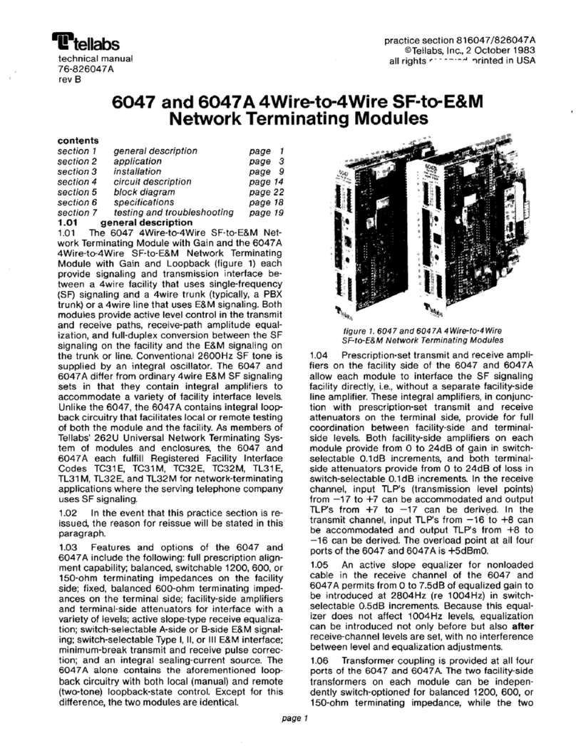
Tellabs
Tellabs 6047 User manual
Tellabs
Tellabs 8820 MSR User guide
Tellabs
Tellabs FlexSym OLT-mini User manual
Tellabs
Tellabs 100 Series User manual
Tellabs
Tellabs FlexSym OLT6 User manual
Popular Network Hardware manuals by other brands

TLS Electronics
TLS Electronics BL 30100 HDBaseT user manual

Keysight
Keysight APS-M8400 installation guide
ZyXEL Communications
ZyXEL Communications NSA-220 Plus user guide
Pacific Communications
Pacific Communications SmartIP-8SD user manual
HP
HP D7171A - NetServer - LPr manual
LAPP
LAPP ETHERLINE GUARD PM03T operating instructions
