Telma AC50-55 User manual

1Feb11
TL113007
INSTALLATION MANUAL
FOR
TELMA AC50-55
ON
CHEVY 4500 EXPRESS/SAVANNA
CUTAWAY
FROM MODEL YEAR 2010

TL113007
Chevrolet 4500 EXPRESS Installation Manual
Page 2 of 21___________________________________________________________________________________1Feb11
TABLE OF CONTENTS
1 Preparation of the Chassis
1.1 Driveline
1.2 Exhaust
1.3 Fuel Tank
2 Telma Installation
2.1 Install the Chassis Brackets
2.2 Install vent tube extension
2.3 Assemble the Telma Brackets and mounts
2.4 Install the Telma in the Chassis
2.5 Drive Shaft Modification and Installation
3 Control Components
3.1 Relay Box Installation
3.2 Light Bar Installation
3.3 Speed Switch and Foot Control Switch Installation
3.4 Foot Switch Adjustment
4 Wiring Harness Installation
4.1 Power Harness Installation
4.2 Control Harness Installation
5 Recommended Tools
6 Post Install Checklist
7 Appendix
Kit List
Chassis Bracket Installation
Bracket Assembly
Wiring Diagram
Wire Harness TID13017
Drive Shaft Modification Guidelines
Axle shim installation
Post Install Checklist
G33803 159” WB Installation Drawing with 6.6L Duramax Diesel
G33803 177” WB Installation Drawing with 6.6L Duramax Diesel (stretched in rear)
G33803 182” WB Installation Drawing with 6.6L Duramax Diesel (stretched in rear)
TL113007
Chevrolet 4500 EXPRESS Installation Manual
Page 3 of 21___________________________________________________________________________________1Feb11
SECTION 1 PREPARATION OF THE CHASSIS
1.1 DRIVELINE
Remove the complete drive-shaft assembly after measurements have been taken.
1.2 EXHAUST
An exhaust modification is needed for all wheelbases to route the exhaust between the Telma side plate bracket
and the frame. Keep all components at least ¼” away from the side plate bracket to prevent vibrations through
the exhaust.
For gasoline engine chassis the exhaust modification may be too complicated (dual pipes and catalytic
converters). Only the diesel chassis installation drawings are included in this manual.
1.3 FUEL TANK
An aft-of-axle fuel tank is required for Telma installation
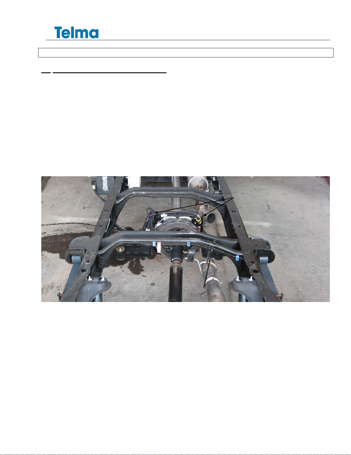
SECTION 2 RETARDER INSTALLATION
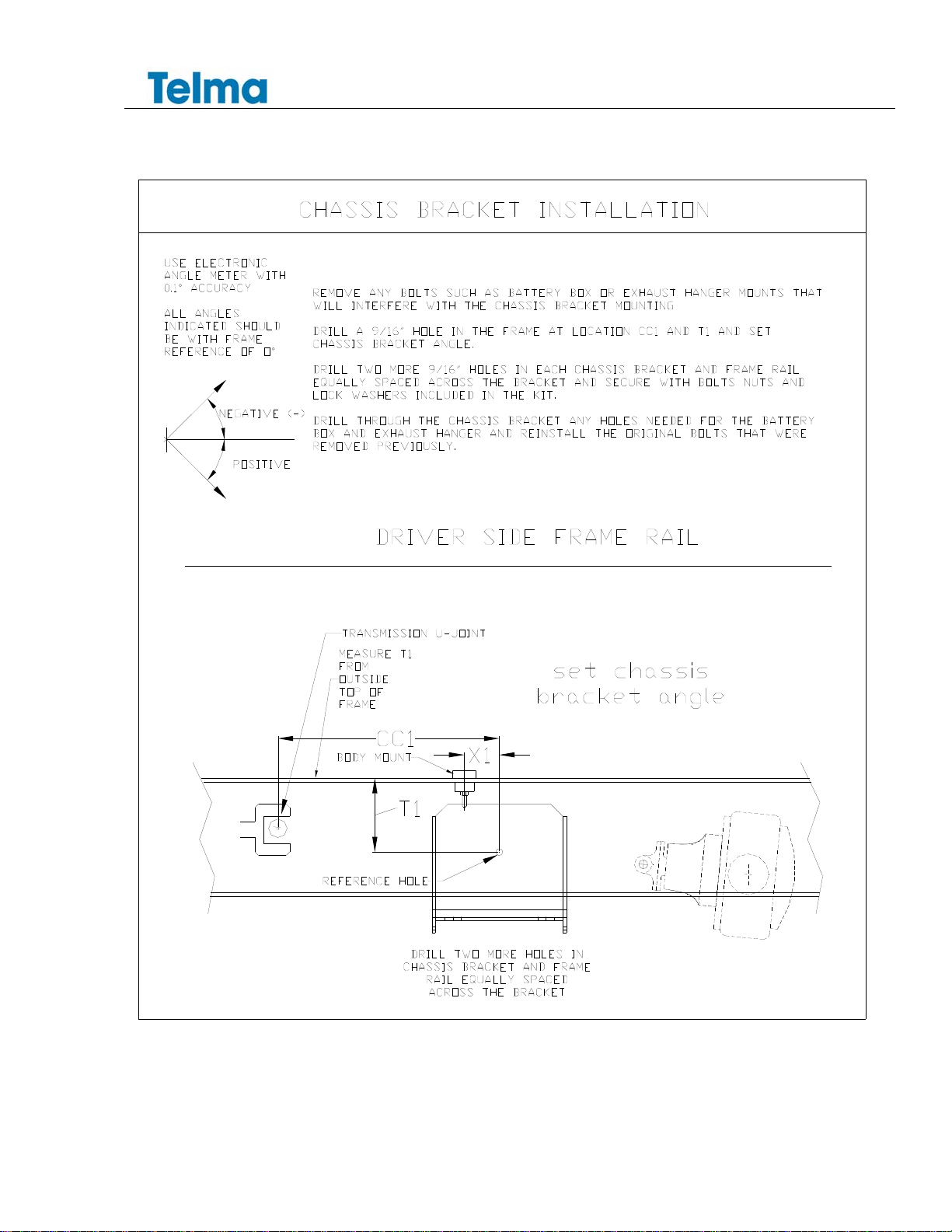
2.1 INSTALLATION OF THE CHASSIS BRACKETS
Remove any bolts such as battery box and/or exhaust hanger mounts that will interfere with the chassis
bracket mounting
Mark the reference hole T1 from the top of the frame down to the reference hole.
Mark the reference hole CC1 from the center of the transmission u-joint or X1 from the body mount hole.
Drill a single 9/16” hole in the frame and bolt the chassis bracket (TIB03125) against the outside of the frame.
Rotate the bracket to the angle specified on the installation drawing.
Drill two more 9/16” holes in the chassis bracket and frame rail keeping away from fuel and brake lines and
secure with bolts (TIF03002), nuts (TIF03003), and lock washers (TIF03004) included in the kit.
Tighten the 9/16” bolts to 150 lb-ft (±10%).
Drill through the chassis bracket any holes needed for battery box and/or exhaust hanger mounts and reinstall
the original bolts that were previously removed. It may be necessary to make a 5/16” spacer to keep the
accessory brackets flush on the outside of the frame rail.
Install the male parts of the rubber mounts into the 1 5/8” holes in the brackets from the bottom. Place one
2-3/4” diameter 5/8” flat washer on the top and bottom of each mount.
Refer to the appendix for detail drawings.
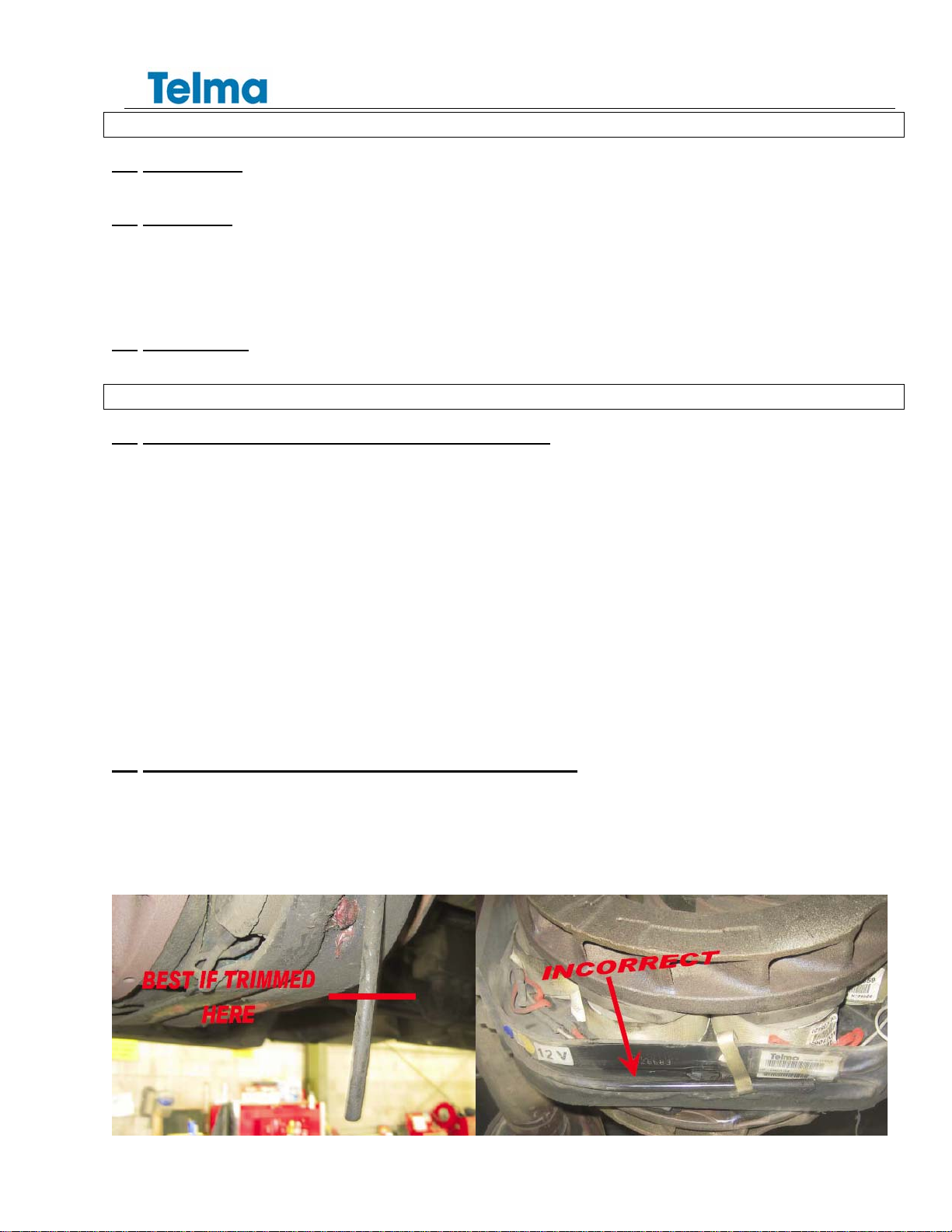
2.2 INSTALLATION OF THE VENT TUBE EXTENSION
At the time of installation the plastic vent tube extension kit should be attached to the grease chamber vent
tube according to the instructions supplied. Install the vent tube before the retarder bracket is installed to
avoid the possibility of crimping the nylon tube and restricting the outlet. The vent tube is located at the upper
passenger side corner of the Telma. Cut off the vent tube at the bottom of the Telma using a knife or cable
cutter. Do not use diagonal cutters which may crimp and restrict the outlet. Do not wrap the vent tube under
the retarder.

TL113007
Chevrolet 4500 EXPRESS Installation Manual
Page 4 of 21___________________________________________________________________________________1Feb11
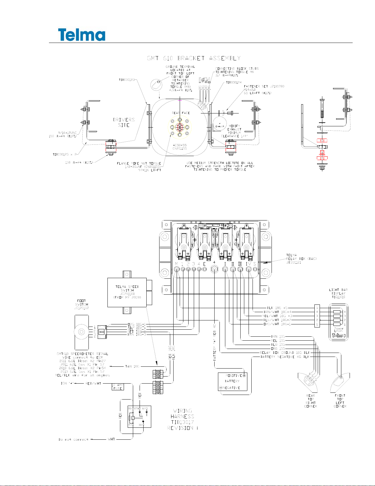
2.3 ASSEMBLY OF THE TELMA BRACKETS AND MOUNTS
Identify the driver’s side of the Telma from the passenger side. To do so, orient the arrow of the red plate on
the Telma towards the axle with the red plate on the driver’s side.
Identify the Telma brackets. The longer bracket TIB03123 is for the driver’s side. The shorter passenger side
bracket is TIB03124.
Use four M14 bolts flat washers and Trep washers provided with the set of fasteners (JZ100280) to fasten the
Telma bracket onto each side of the unit. Tighten bolts to 65 lb.-ft (±10%).
Refer to the appendix for detailed drawings.
Assemble the mounts to the side plate brackets with the female portion of the mounts on the top side of the
brackets.
2.4 INSTALLATION OF THE TELMA IN THE CHASSIS
Install the Telma, equipped with the side plate brackets to the chassis brackets in the hanging position.
Secure the Telma to the chassis brackets using the 16mm diameter x 110mm long bolts through the holes in
the chassis brackets, mounts and side plate brackets. At each mount, install the 2 3/4” diameter flat washer,
the 5/8” lock nut and tighten to 150 lb.-ft (±10%).
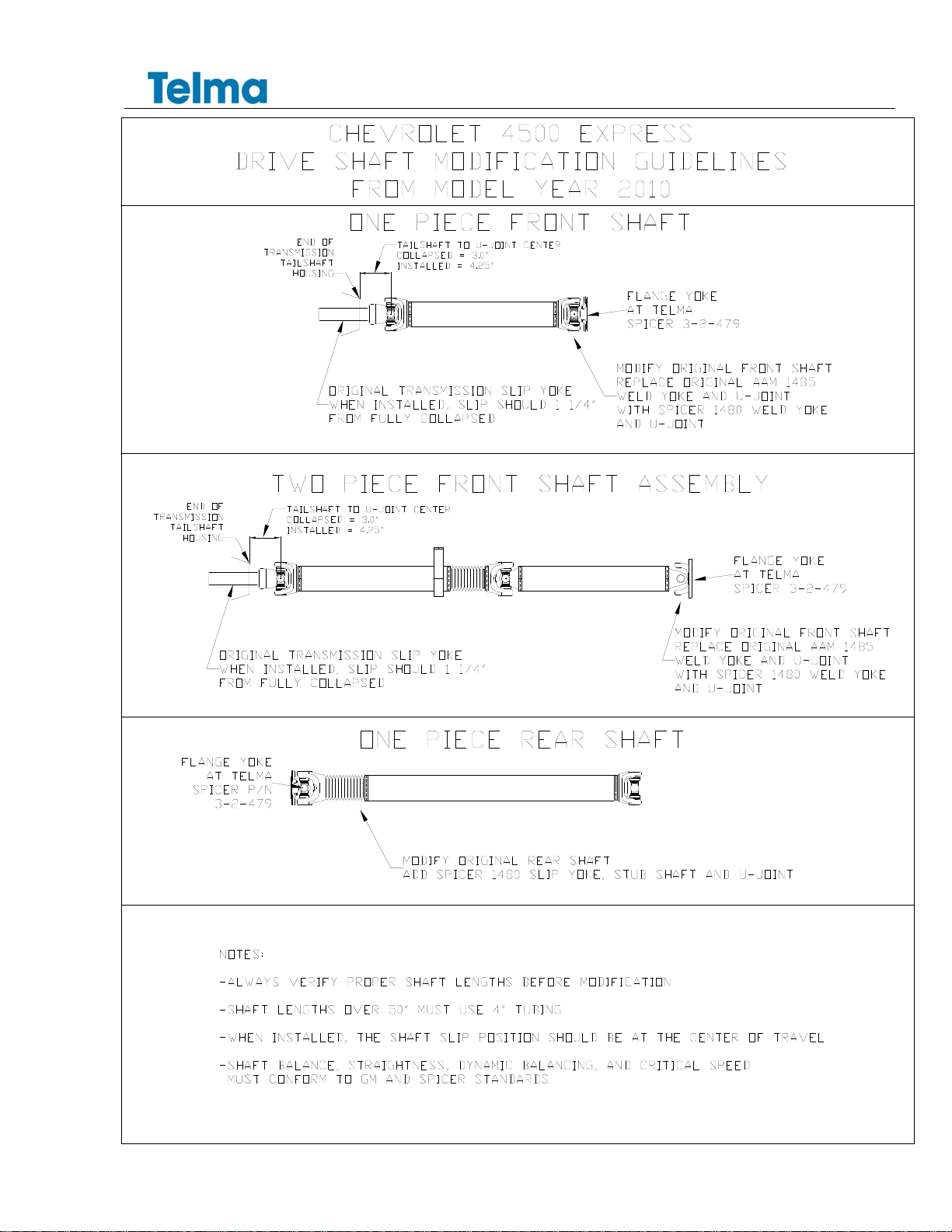
2.5 DRIVE SHAFT MODIFICATION AND INSTALLATION
A slip assembly is required on each side of the Telma. The slip position should be at center of slip travel when
the shaft is installed.
Refer to GM Upfitters guidelines for proper drive shaft manufacture, balance, straightness, and critical speed
limits.
Refer to the appendix for Telma guidelines.
Refer to the installation drawings in the appendix for shaft length guidelines.
Shaft lengths over 50” should use 4” tubing.
Always verify proper shaft lengths before modification.
Connect the flange yoke of each drive shaft to the Telma coupling flange using the supplied locknuts.
CN201155: Tighten the 1/2”-20UNF all metal lock nuts to 97-116 lb-ft.
TL113007
Chevrolet 4500 EXPRESS Installation Manual
Page 5 of 21___________________________________________________________________________________1Feb11
SECTION 3 CONTROL SYSTEM COMPONENTS INSTALLATION
3.1 RELAY BOX MOUNTING
Install the relay box on the driver side frame rail using an existing hole from the battery box if the batteries will
be relocated and if available approximately 40” forward from the center of the Telma and down 3 1/2“, from
the top of the frame rail using the relay box mounting brackets TIB01017 x 2 and fasteners supplied in the kit.
Tighten the four 5/16” bolts to 17 lb-ft (±10%) and the two ½” bolts to 75 lb-ft (±10%).
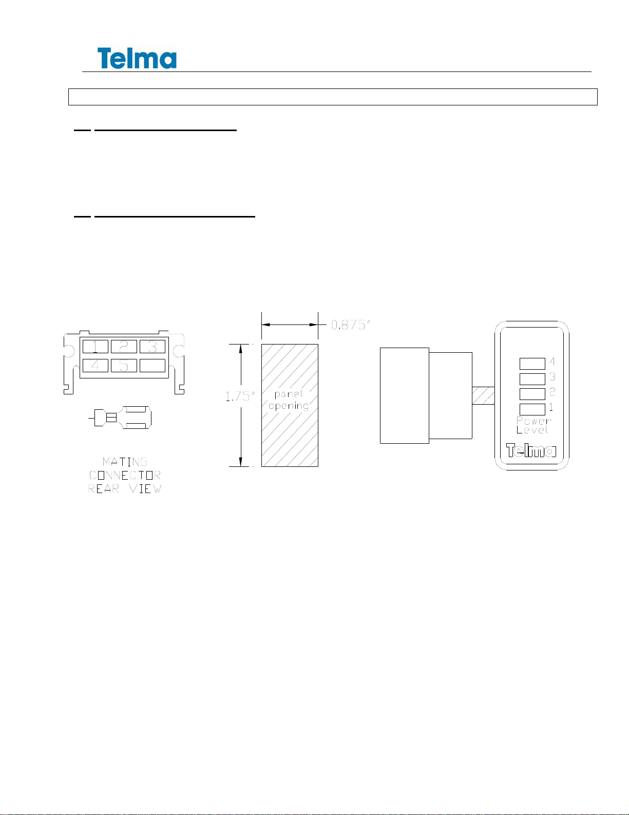
3.2 LIGHT BAR INSTALLATION
The Light Bar should be mounted so that it is easily visible to the driver.
Make a rectangular hole, 7/8” wide x 1 ¾” tall in the lower dash to the right of the steering column or install the
Light Bar in an existing console receptacle.
Feed the harness through the hole and connect to the Light Bar.
Plug the light bar into the hole.
LIGHT BAR
DISPLAY
PANEL OPENING
TL113007
Chevrolet 4500 EXPRESS Installation Manual
Page 6 of 21___________________________________________________________________________________1Feb11
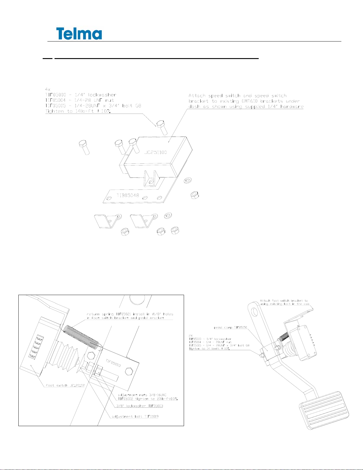
3.3 SPEED SWITCH & FOOT CONTROL SWITCH INSTALLATION
Bracket TIB05048 is used to mount the Telma speed switch.
Bracket TIB05049 is used to mount the foot switch to the dash as shown.
Attach pedal clamp TIB05050 and pedal bracket TIB05053 to the brake pedal using the ¼” bolts, nuts and lock
washers supplied in the kit.
Attach the return spring TIB05021using the 1/8” holes in the pedal bracket and foot switch bracket.
The special 3/8” adjustment bolt, nuts and lock washers are assembled as shown below.
TL113007
Chevrolet 4500 EXPRESS Installation Manual
Page 7 of 21___________________________________________________________________________________1Feb11
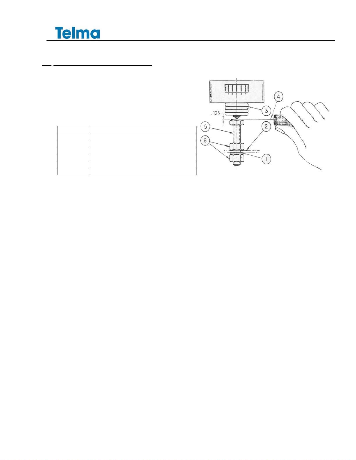
3.4 FOOT SWITCH ADJUSTMENT
The plunger type foot switch should be carefully adjusted
to avoid switch damage and optimize retarder activation in
the free play of the pedal. With the return spring installed,
use a feeler gauge and adjust the switch stop (item 5) until
there is 1/8” gap. The switch plunger should be fully
compressed and the brake pedal should be in its highest
position.
ITEM DESCRIPTION
1 3/8” lock washer
2 Pedal bracket
3 foot switch JC120102
4 feeler gauge
5 3/8” diameter switch stop adjusting bolt
6 3/8” jam nuts
TL113007
Chevrolet 4500 EXPRESS Installation Manual
Page 8 of 21___________________________________________________________________________________1Feb11
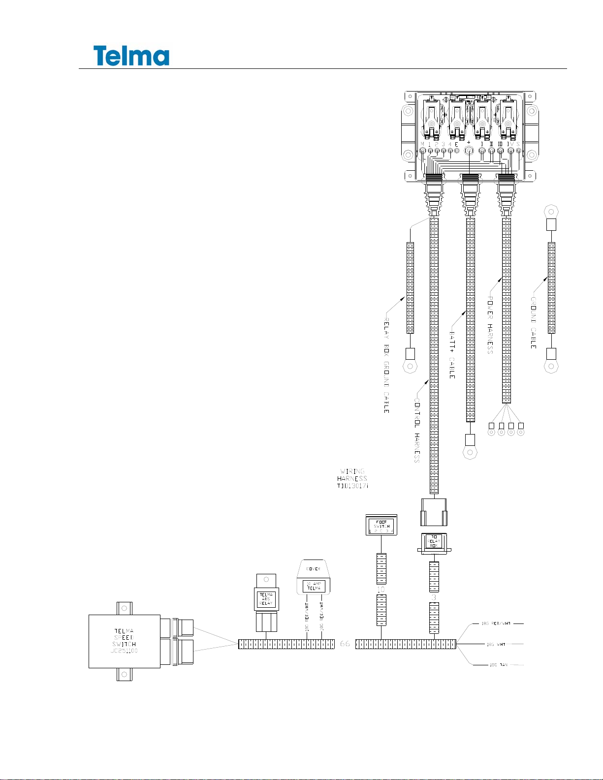
SECTION 4 WIRING HARNESS INSTALLATION
4.1 POWER HARNESS INSTALLATION
From the relay box, route the Telma power connection and ground harness along the inside of the frame rail
and up over the top along the middle of the Telma. Connect the 10G orange, blue, yellow, and brown wires to
the connecting block at the top right rear corner. Connect the 10G relay box ground cable and the 4G Telma
main ground cable to the insulated ground terminal at the Telma top left front corner. Coat the terminals with
anti-corrosion paint or body undercoat after the connections are made. Secure the harness to the center of
the Telma brackets with rubber coated cable clamps. The harness should be secured along the centerline of
the Telma and as far away as possible from either rotor to avoid heat damage to the harness. No cables
should cross the heat outlets in the periphery of the rotors. Continue across with the black 4G ground cable
and connect to negative terminal of the battery pack. If necessary route the red power positive cable along the
cross member in front of the Telma and connect to the positive terminal of the battery pack. Secure the cable
to the cross member with rubber coated cable clamps.
Attach Harness to
brackets using rubber
coated cable clamps

TL113007
Chevrolet 4500 EXPRESS Installation Manual
Page 9 of 21___________________________________________________________________________________1Feb11
4.2 CONTROL HARNESS INSTALLATION
Route the control harness into the cab through the rubber grommet in the floor under the driver’s seat. Follow
the OEM harness under the carpet to the dashboard. Connect the main harness to the subharness at the
connector labeled “TO RELAY BOX”.
Find the speed switch harness and plug the two speed switch plugs into the speed switch. Plug the foot
switch connector onto the foot switch so that the orange and blue wires are on terminal 1.
Connect the Foot Control Limit Switch (TIG31061) into an appropriate ignition “+” source at the fuse panel or
bodybuilders plug.
Connect the RED/WHT fused wire into the other side of the Limit Switch.
Feed the Tan speed signal wire through the firewall and into the engine compartment or use pass through
circuits if available. Connect the Telma tan wire to Chevy speed signal out YEL/BLK wire ECM X2 connector
pin 54 for 2010 and older chassis and pin 27 for 2011 diesel engines. Do not connect the Telma white wire.
Use weather tight connectors and heat shrink for the speed signal. Add a small amount of heat shrink on the
end of the white wire.
Feed the harness equipped with the light bar mating connector through the light bar hole and plug in the light
bar.
Plug the light bar into the hole.

TL113007
Chevrolet 4500 EXPRESS Installation Manual
Page 10 of 21___________________________________________________________________________________1Feb11
SECTION 5 RECOMMENDED TOOLS
Transmission Jack
Heavy duty drill motor
Standard assortment of mechanics hand tools
Vehicle hoist, pit, or floor jack with stands
Electrical connector crimping pliers for use with non-insulated connectors
Dana Anglemaster electronic angle meter
SECTION 6 POST INSTALL CHECKLIST
Use checklist TIL05064 to check that correct installation was performed and file in the vehicle records

TL113007
Chevrolet 4500 EXPRESS Installation Manual
Page 11 of 21___________________________________________________________________________________1Feb11
APPENDIX

TL113007
Chevrolet 4500 EXPRESS Installation Manual
Page 12 of 21___________________________________________________________________________________1Feb11
TIK10308 CHEVY 4500 EXPRESS CHASSIS kit for MY2010
P/N DESCRIPTION QTY
CN201155 AC50-55 / 12V 1480 1
TIB03123 CHEVY GMT 610 PASSENGER SIDE BRACKET 1
TIB03124 CHEVY GMT 610 DRIVER SIDE BRACKET 1
TIB03125 CHEVY GMT 610 CHASSIS BRACKET 2
JZ100280 SIDE PLATE FASTENERS 1
JZ1007XX-30 TELMA SHOCK MOUNT SET (30 SHORE) 1
VF120340 SELF-LOCKING NUT 155 INDEX 8
TIF03003 NUT 9/16 - 12 UNC G8 6
TIF03005 LOCKWASHER 9/16 G8 6
TIF04001 BOLT 9/16 - 12 UNC X 2 HEX HEAD G8 6
TID13017 HARNESS W/ JD331121 1
TIB01017 CONTROL / RELAY BOX BRACKET 2
JC251100 12V SPEED SWITCH 3.3 TRG 1
TIB05048 CHEVY GMT SPEED SWITCH BRACKET 1
TIB05049 CHEVY GMT FOOT SWITCH BRACKET 1
TIB05050 CHEVY GMT PEDAL CLAMP 1
TIB05053 CHEVY GMT PEDAL BRACKET 1
JC120102 FOOT SWITCH 1
TIG11010 TELMA LIGHT BAR DISPLAY 1
TIF05021 MUSIC WIRE / RETURN SPRING 1
TIG31061 FOOT CONTROL LIMIT SWITCH 1
TIL08001 CAUTION LABEL 1
TIF05000 LOCKWASHER 1/4 SPLIT 6
TIF05002 NUT 3/8 - 16 UNC G5 2
TIF05003 LOCKWASHER 3/8 G5 SPLIT 1
TIF05004 NUT 1/4 - 28 UNF G8 6
TIF05005 BOLT 1/4 - 28 UNF X ¾ HEX HEAD G8 6
TIF05010 LOCKWASHER 5/16 SPLIT 4
TIF05011 NUT 5/16 4
TIF05012 BOLT 5/16 - 18 UNC X 1-3/4 HEX HEAD G5 4
TIF05013 BOLT 1/2 - 13 UNC X 1-1/2 HEX HEAD G5 2
TIF05019 ELEVATOR BOLT 3/8 - 16 UNC 2-1/2 1
LITJZ100110 PRODUCT INFO 1
JZ100110 DISCHARGE ASSEMBLY 1
Note:
Flange yokes Spicer part number 3-2-479 (Telma part number TIF01081) must be ordered separately.
TL113007
Chevrolet 4500 EXPRESS Installation Manual
Page 13 of 21___________________________________________________________________________________1Feb11
TL113007
Chevrolet 4500 EXPRESS Installation Manual
Page 14 of 21___________________________________________________________________________________1Feb11
WIRING HARNESS TID13017i
TL113007
Chevrolet 4500 EXPRESS Installation Manual
Page 15 of 21___________________________________________________________________________________1Feb11
TL113007
Chevrolet 4500 EXPRESS Installation Manual
Page 16 of 21___________________________________________________________________________________1Feb11
TL113007
Chevrolet 4500 EXPRESS Installation Manual
Page 17 of 21___________________________________________________________________________________1Feb11
TAN
TL113007
Chevrolet 4500 EXPRESS Installation Manual
Page 18 of 21___________________________________________________________________________________1Feb11
INSPECTION LOCATION:
INSPECTED BY:
Customer:
Body Manufacturer:
chassis Make / Model:
engine:
Wheelbase:
Telma installed by:
PHYSICAL
CHECKS
The following checks should be made after the installation is completed. A copy of the completed
inspection report should be kept in the vehicle file.
Batteries
The battery pack must consist of 2 batteries connected in parallel equivalent to diesel OEM capacity.
Cable size should be at least as heavy as the OEM battery cables and should not be less than
4AWG.
Telma Batt "-"
and "+" cables
The Telma battery cables (4AWG) must be connected to the terminal of the battery pack or to a
remote mounted post connected directly to the post of the batterypack with at least a 4AWG cable.
Protect the connection with anti-corrosion paint or body undercoating.
The relay box should be mounted in a vertical position.
The relay box should be away from heat sources and moving components to prevent damage.
The relay box placement should allow easy removal of the cover for inspection.
All harnesses should exit from the bottom of the relay box and be secured with a drip loop.
Telma
The power connecting block should be at the top right rear corner of the Telma.
The Telma ground terminal should be at the top left front corner of the Telma.
Heat sensitive chassis components should be no closer than 4 inches from the Telma rotors.
The Telma power and ground connections should be protected with anti-corrosion paint or coating.
vent tube installation
Speed Switch
The Telma speed switch should be located under the driver side dash with the connectors oriented
for easy access to repair and test.
Foot Switch
When the brake pedal is in the highest position, the Telma foot switch should be adjusted so that
there is a 1/8" gap between the fully compressed foot switch plunger and the pedal bracket.
There should be a return spring installed between the foot switch bracket and the pedal bracket in
order to maintain the brake pedal in the highest position when released.
The Telma foot switch should be oriented so that the wiring connector points up and away from the
driver's foot.
Indicator Li
g
hts
The Telma Light Bar Display should be mounted where it is easily visible to the driver.
General Wiring
The control harness and battery connection cables should be secured with cable clamps and routed
along the inside of the frame rail wherever possible.
All harnesses should be positioned at least 6 inches from exhaust system components or protected
with high temperature insulation and heat shields.
Avoid sharp edges that could cause damage.
At least 3 inches clearance should be maintained from moving or rotating components.
Install grommets in holes through sheet metal.
V
ehicle Wirin
g
The vehicle speed signal connection must use a weatherproof connector.
Connections
Use of a "quick splice" type connector is strictly prohibited.
Control Harness
The Telma control harness should be routed along the inside of the driver side frame rail from the
relay box toward the front of the chassis.
It should enter the cab through an existing hole under the driver side stepwell and be routed behind
the left kick panel and up under the dash toward the steering column area. Make sure the harness
does not interfere with the parking brake mechanism and cannot be damaged when the parking
brake is applied.
Power Harness
Harnesses connected to the retarder should be positioned along the center of the retarder frame as
far away as possible from either retarder rotor and secured to the retarder bracket with rubber-coated
metal cable clamps.
Drive Shafts
Drive shafts must be equipped with universal joints of the same type as supplied by the OEM.
The front drive shaft must be equipped with a slip yoke.
When the shaft is installed, the 3" slip should be extended approximately 1 1/2".
The rear drive shaft must be equipped with the same type of slip yoke as supplied by the OEM and
installed toward the front at the rear of the retarder.
When the shaft is installed, the slip should be extended approximately 1 1/2".
Front and rear Telma yokes should be in the same plane.
Installation
drawin
g
Drive shaft lengths and angles should conform to the installation drawing. An electronic anglemeter
with 0.1 degree accuracy must be used. Contact Telma for recommendations.
Post install
all angle measurements are with chassis reference of 0 degrees (zero meter on frame)
check
Check and record measurements and compare to the installation drawing used.
Place a copy of this checklist and the install drawing used in the vehicle file
ANGLE LENGTH
TRANSMISSION ANGLE
(FRONT SHAFT INSTALLED LENGTH AND ANGLE) L1
(REAR OR SECOND SHAFT INSTALLED LENGTH AND ANGLE) L2
( REAR SHAFT IN A THREE SHAFT SYSTEM INSTALLED LENGTH AND ANGLE) L3
TELMA ANGLE
(outside top of frame to lower chassis bracket hole) T1
(body mount to lower chassis bracket hole) X1
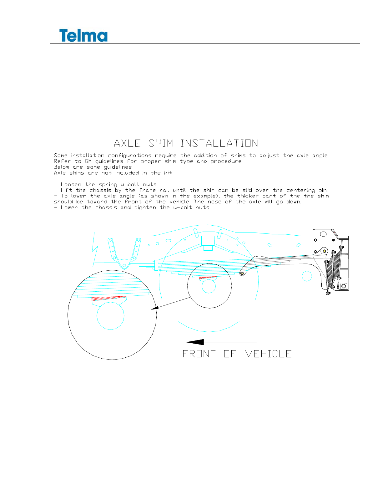
AXLE ANGLE
Mor-Ryde Suspension (yes/no)
axle shims installed (yes/no)
Road Test
The four dash lights illuminate progressively when the brake pedal is applied and vehicle is moving.
Telma turns off when the brake pedal is released and vehicle is moving.
Telma turns off automaticallywhen the vehicle comes to a stop
The four dash lights do not illuminate if the brakes are not applied
No vibrations noticed during road test up to speed limit
INSPECTION COMMENTS
Relay Box
OPERATIONAL CHECKS

TL113007
Chevrolet 4500 EXPRESS Installation Manual
Page 19 of 21___________________________________________________________________________________1Feb11
TELMA RETARDER
,
INC
870 Livel
y
Blvd
,
Wood Dale
,
IL 60191
Tel:
(
847
)
593-1098 Fax:
(
847
)
593-3592
V
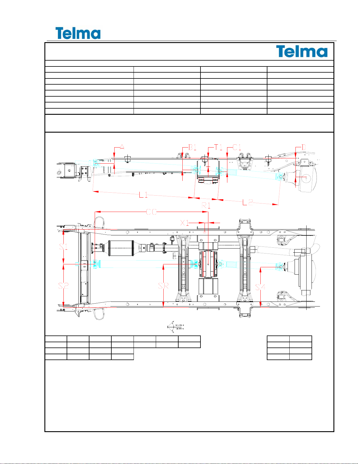
EHICLE TECHNICAL DATA
CHASSIS MAKE / MODEL CHEVROLET 4500 EXPRESS SPEED SWITCH JC251100
WHEELBASE 159.0" TIRE SIZE 225/75R-16
ENGINE MAKE / MODEL CHEVROLET 6.6L GVW / GCW 14200 lbs
TRANSMISSION MAKE / MODEL CHEVROLET 4L85E AXLE RATIO 4.10 3.73 optional
AXLE MAKE / MODEL AMERICAN AXLE DRIVE LINE SERIES 1485
DRIVE TYPE 4 X 2 Use OEM U-JOINT
RETARDER MODEL AC50-55 FLANGE YOKE 3-2-479
RETARDER PART NUMBER CN201154 SUSPENSION Spring
TELMA attests that this drawing corresponds to industry standards concerning driveline angularities and critical speeds
This drawing is valid for the application specified only. Always check all angles and dimensions for your installation.
Consult TELMA technical department if your application varies in any way Dc loaded:
9 3/4
Dv unloaded:
10 3/4
TRANSMISSION= 3.3° CHASSIS BRACKET= 0.0°
L2 UNLOADED WITH BODY (±1.0°) =
6.6° AXLE UNLOADED= 4.6°
L1= 3.9° RETARDER= 4.5°
L2 LOADED (±1.0°) =
4.8° AXLE LOADED= 4.5°
AB1C1R1T1X1
CC L1 L2
2 3/4 6 1/4 7 3/16 12 1/16 4 1/2 1 3/4 57
SHAFT LENGTH
51 1/16 30 5/8
S1 S2 S4 SR
SHAFT MINIMUM TUBE DIAMETER
4.00 3.00
18 3/4 23 1/4 21 3/4 23 1/4
SHAFT MINIMUM TUBE THICKNESS
0.083 0.083
NOTE 1: Drive shaft lengths are measured from center of U-joint and are installed lengths.
angle tolerance=±0.2°
NOTE 2: All drive shafts must be dynamically balanced after modification.
dimension tolerance=±1/16"
NOTE 3:
Always verify proper shaft lengths before modification
NOTE 4:
When not specified, the front & the rear drive shafts, on each retarder side, must have at least the same slip as the original drive shaft
NOTE 5:
When not specified, the flange yoke on each retarder side must have the maximum working angle capacity available in the driveline series concerned.
NOTE 6: adjust retarder to angle indicated by rotating bracket
NOTE 7:
After installation is completed, measure drive shaft angles and compare to the angles on the installation drawing.
Contact TELMA Customer Support Engineering if the angles measured do not conform to the drawing
NOTE 8: Use brackets TIB03123, TIB03124, TIB03125
NOTE 9:
Check axle angle after body is installed and if necessary adjust to 4.5° with frame reference of 0°
NOTE 10: maximum allowed vehicle speed 79mph
TL113007
Chevrolet 4500 EXPRESS Installation Manual
Page 20 of 21___________________________________________________________________________________1Feb11
TELMA RETARDER
,
INC
870 Livel
y
Blvd
,
Wood Dale
,
IL 60191
Tel:
(
847
)
593-1098 Fax:
(
847
)
593-3592
V
EHICLE TECHNICAL DATA
CHASSIS MAKE / MODEL CHEVROLET 4500 EXPRESS SPEED SWITCH JC251100
WHEELBASE 177.0" STRETCH FROM 159 TIRE SIZE 225/75R-16
ENGINE MAKE / MODEL CHEVROLET 6.6L GVW / GCW 14200 lbs
TRANSMISSION MAKE / MODEL CHEVROLET 4L85E AXLE RATIO 4.10 3.73 optional
AXLE MAKE / MODEL AMERICAN AXLE DRIVE LINE SERIES 1485
DRIVE TYPE 4 X 2 Use OEM U-JOINT
RETARDER MODEL AC50-55 FLANGE YOKE 3-2-479
RETARDER PART NUMBER CN201154 SUSPENSION Spring
TELMA attests that this drawing corresponds to industry standards concerning driveline angularities and critical speeds
This drawing is valid for the application specified only. Always check all angles and dimensions for your installation.
Consult TELMA technical department if your application varies in any way Dc loaded:
9 3/4
Dv unloaded:
10 3/4
TRANSMISSION= 3.3° CHASSIS BRACKET= 0.0°
L2 UNLOADED WITH BODY (±1.0°) =
4.2° AXLE UNLOADED= 4.6°
L1= 3.9° RETARDER= 4.5°
L2 LOADED (±1.0°) =
3.0° AXLE LOADED= 4.5°
AB1C1R1T1X1CC L1L2
2 3/4 6 1/4 7 3/16 12 1/16 4 1/2 1 3/4 57
SHAFT LENGTH
51 1/16 48 5/8
S1 S2 S4 SR
SHAFT MINIMUM TUBE DIAMETER
4.00 4.00
18 3/4 23 1/4 21 3/4 23 1/4
SHAFT MINIMUM TUBE THICKNESS
0.083 0.083
NOTE 1: Drive shaft lengths are measured from center of U-joint and are installed lengths.
angle tolerance=±0.2°
NOTE 2: All drive shafts must be dynamically balanced after modification.
dimension tolerance=±1/16"
NOTE 3:
Always verify proper shaft lengths before modification
NOTE 4:
When not specified, the front & the rear drive shafts, on each retarder side, must have at least the same slip as the original drive shaft
NOTE 5:
When not specified, the flange yoke on each retarder side must have the maximum working angle capacity available in the driveline series concerned.
NOTE 6: adjust retarder to angle indicated by rotating bracket
NOTE 7:
After installation is completed, measure drive shaft angles and compare to the angles on the installation drawing.
Contact TELMA Customer Support Engineering if the angles measured do not conform to the drawing
NOTE 8: Use brackets TIB03123, TIB03124, TIB03125
NOTE 9:
Check axle angle after body is installed and if necessary adjust to 4.5° with frame reference of 0°
NOTE 10: maximum allowed vehicle speed 79mph
Table of contents
Other Telma Industrial Equipment manuals


