Telma AF8 User manual
MAINTENANCE MANUAL
This document is the property of Telma. It cannot be copied, forwarded, or given to any party without prior agreement form TELMA. Any infringement will immediately involve legal action.
TELMA S.A., 28 rue Paul Painlevé, F-95310 Saint-Ouen l’Aumône - www.telma.com 1 / 18 OC441691
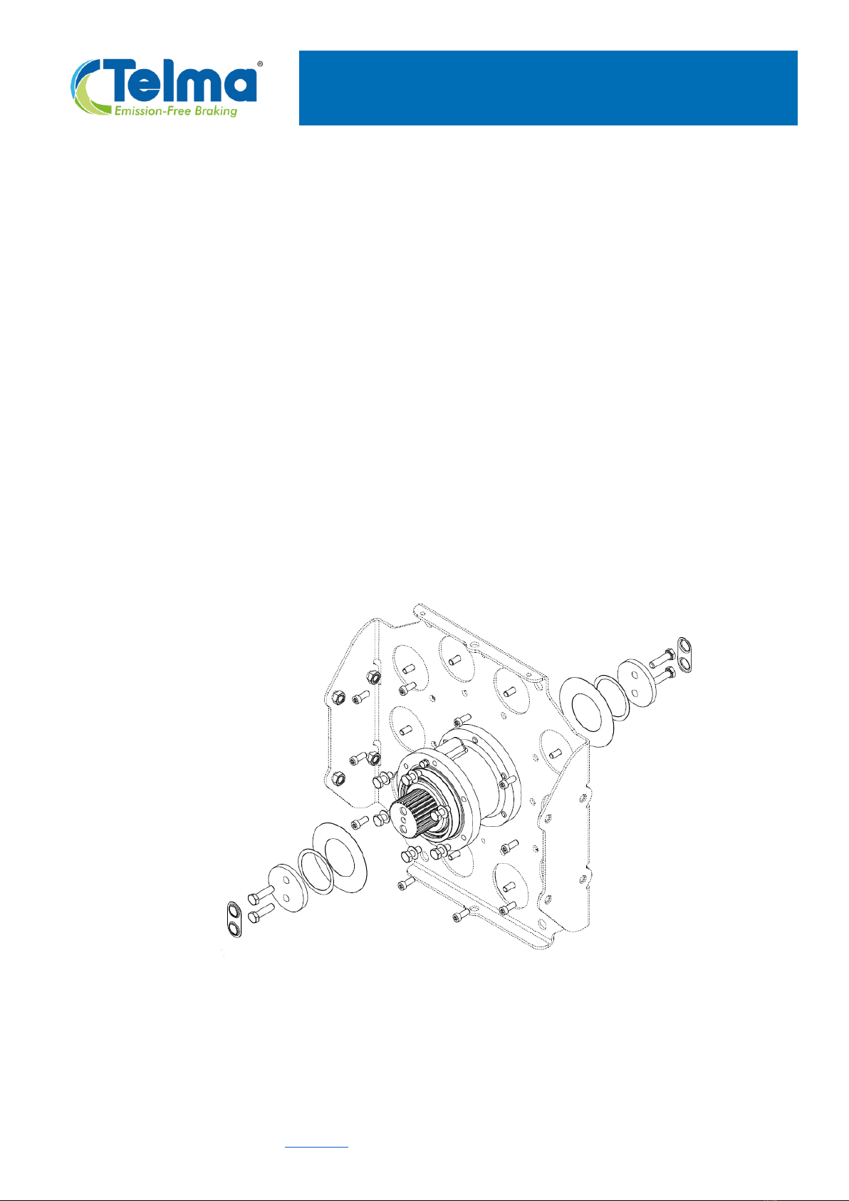
The following instructions define how to replace the hub on
Axial retarders LM/LN/LP/LR/LTxxxxxx
Hub replacement on AF8
retarder range

MAINTENANCE MANUAL
This document is the property of Telma. It cannot be copied, forwarded, or given to any party without prior agreement form TELMA. Any infringement will immediately involve legal action.
TELMA S.A., 28 rue Paul Painlevé, F-95310 Saint-Ouen l’Aumône - www.telma.com 2 / 18 OC441691
1. TELMA GENUINE SPARE PART NEEDED...............................................................................................3
2. SAFETY PRECAUTIONS........................................................................................................................3
3. REQUIRED TOOLS................................................................................................................................4
4. PARTS TO BE REPLACED SYSTEMATICALLY ........................................................................................ 5
5. NOTES .................................................................................................................................................5
6. DISMANTLING STEPS...........................................................................................................................6
A. REMOVAL OF ROTORS....................................................................................................................6
B. RETARDER STATOR OPENING.......................................................................................................... 8
C. REMOVAL OF THE DEFECTIVE HUB .................................................................................................9
7. RE ASSEMBLING STEPS......................................................................................................................11
A. INSTALLATION OF THE NEW COMPLETE HUB................................................................................11
B. INSTALLATION OF THE ROTORS ....................................................................................................15
8. ANNEX.............................................................................................................................................. 18
B. TAB WASHER DRIVER ....................................................................................................................18

MAINTENANCE MANUAL
This document is the property of Telma. It cannot be copied, forwarded, or given to any party without prior agreement form TELMA. Any infringement will immediately involve legal action.
TELMA S.A., 28 rue Paul Painlevé, F-95310 Saint-Ouen l’Aumône - www.telma.com 3 / 18 OC441691
1. TELMA GENUINE SPARE PART NEEDED
Hub assembly >> See spare parts catalogue for reference.
For any spare parts orders, it is necessary to specify the part number of the retarder
the model, engraved on the front stator housing, in the upper left corner.
You will find the necessary information on spare parts for this equipment in the spare parts
catalogue:
OC443068 Spare Parts AF8 Telma Retarder
For more information about your TELMA product, please contact your TELMA dealer or the TELMA
technical department.
2. SAFETY PRECAUTIONS
Before repairing your retarder, you must have read this maintenance manual thoroughly.
All operations and interventions for repairing this retarder will be carried out by qualified
personnel.
Our technical support is available for all the information you may need.
The various operations described in this manual are accompanied by recommendations or
symbols to alert the user to the risk of accidents. You must understand and respect the following
warnings below.
Using and safety warning symbol, for an operation capable of damaging or destroying
the retarder or surrounding equipment. The no respect of these warnings can cause
injuries from mild to severe.
Safety warning symbol for an immediate danger to personnel. The no respect of this
warning can cause serious injuries.

MAINTENANCE MANUAL
This document is the property of Telma. It cannot be copied, forwarded, or given to any party without prior agreement form TELMA. Any infringement will immediately involve legal action.
TELMA S.A., 28 rue Paul Painlevé, F-95310 Saint-Ouen l’Aumône - www.telma.com 4 / 18 OC441691
Safety warning symbol for an electrical danger to personnel. The no respect of this
warning can cause serious injuries.
The repair methods described by TELMA SA, in this document, are based on the technical
specifications in effect at the date of this writing. They are subject to modifications in case of
changes done by TELMA SA to manufacture the various component units and accessories brand
(?) products.
The company TELMA SA reserves the right to modify the characteristics of its products at any time
in order to incorporate the latest technological developments. The information contained in this
document are subject to change without notice.
-We would like to draw your attention to the contents of this maintenance manual.
Indeed, following the respect of important points during installation, use and maintenance
of your retarder will ensure trouble-free operation for many years.
-When using lifting equipment, do not walk or stand under suspended loads.
-For information, a complete retarder weights around 330 kg (728 lb), a rotor with coupling
flange weights about 63kg (139 lb), and a hub weights 5.5 kg (12 lb).
-Put the retarder on a solid table, with the handling safety tool.
-Pay attention to the heavy parts of the retarder which can cause serious personal injury.
3. REQUIRED TOOLS
-Protective glasses and gloves
-Handling safety tools for retarder
-Flat screwdriver
-Torx® TX40 socket
-Click-type wrench
-10 mm long socket and 19mm socket
-Tab washer driver (See Annexe 1)
-Hammer
-Feeler gauge
-Dial gauge with magnetic base
-Ink marker
-Torque wrench (torque values: 45Nm, 60Nm and 68Nm)
-Abrasive cloth (120 grade)

MAINTENANCE MANUAL
This document is the property of Telma. It cannot be copied, forwarded, or given to any party without prior agreement form TELMA. Any infringement will immediately involve legal action.
TELMA S.A., 28 rue Paul Painlevé, F-95310 Saint-Ouen l’Aumône - www.telma.com 5 / 18 OC441691
4. PARTS TO BE REPLACED SYSTEMATICALLY
When removed, the following parts need to be replaced by the new ones which are supplied
with the spare hub assembly:
-Shaft end screws, washers, air gap adjusting shims and lock tabs
-Screws used to secure hub
-Screws used to secure pole shoes plate
-Dust protection washers
5. NOTES
Some parts handled during the maintenance operations are covered with a special product
against corrosion. Take precautions when handling to prevent damage to these protections.
For ease and given the diversity of installations on vehicles, this procedure has been done with the
retarder removed from the vehicle and its accessories (retarder brackets) removed from the
retarder.
To remove the retarder brackets, please refer to the appropriate procedures.
The different pictures on this procedure are generic views and are not contractual.
MAINTENANCE MANUAL
This document is the property of Telma. It cannot be copied, forwarded, or given to any party without prior agreement form TELMA. Any infringement will immediately involve legal action.
TELMA S.A., 28 rue Paul Painlevé, F-95310 Saint-Ouen l’Aumône - www.telma.com 6 / 18 OC441691
6. DISMANTLING STEPS
A. REMOVAL OF ROTORS
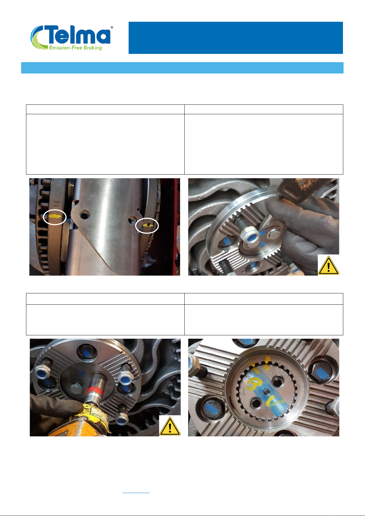
IMPORTANT: identify all parts before dismantling in order to find their initial orientations and
location during the re-assembly.
6A-1
6A-2
Draw a mark on each rotor outer edge with an ink
marker, the two marks must be aligned to find
again the initial angular orientation during re-
assembly. This is essential to maintain proper
balancing.
On the first retarder side (for instance here the
gearbox side, with the engraved part and serial
numbers), remove the lock tab by using a flat
screwdriver and a hammer. Caution: in order to
reduce the spring effect, suppress the stress in the
tab by hitting on one side and by removing the
other).
6A-3
6A-4
Unscrew the 2 shaft end screws to remove them.
Use a 19mm socket and a bar to lock the rotation
of the rotor.
Draw a mark on both shaft and coupling flange
with an ink marker, to find again the initial position.

MAINTENANCE MANUAL
This document is the property of Telma. It cannot be copied, forwarded, or given to any party without prior agreement form TELMA. Any infringement will immediately involve legal action.
TELMA S.A., 28 rue Paul Painlevé, F-95310 Saint-Ouen l’Aumône - www.telma.com 7 / 18 OC441691
6A-5
6A-6
Insert a lifting hook between 2 cooling fins on the
frontal face of the rotor to facilitate pull off of the
rotor and coupling flange assembly.
Remove the dust shield from the shaft.
6A-7
6A-8
Remove from the shaft the air gap adjusting shims
and the 0.70mm black shim with Nuflon coating.
Do the same steps from 6A-2 to 6A-7 for the other
rotor (drive axle side).
Dust shim
Black shim
Shims used
to set air
gap

MAINTENANCE MANUAL
This document is the property of Telma. It cannot be copied, forwarded, or given to any party without prior agreement form TELMA. Any infringement will immediately involve legal action.
TELMA S.A., 28 rue Paul Painlevé, F-95310 Saint-Ouen l’Aumône - www.telma.com 8 / 18 OC441691
B. RETARDER STATOR OPENING
6B-1
6B-2
Unscrew and remove the 6 screws securing the
hub on gearbox side. Use a 19mm socket.
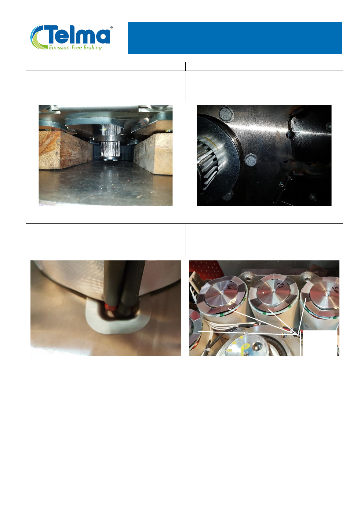
Put the stator in horizontal position (gearbox side
with the removed hub screws down) on wooden
blocks to protect the shaft. The wood beams must
be thick enough in order that the shaft does not
touch the table and for providing hand access for
further operations.
6B-3
6B-4
On the upper side, unscrew and remove the 6
screws securing the hub on axle side. Use a 19mm
socket.
On the upper side, remove the 10 screws securing
the pole shoes plate, using a Torx® TX40 socket.
Zone for
hand access

MAINTENANCE MANUAL
This document is the property of Telma. It cannot be copied, forwarded, or given to any party without prior agreement form TELMA. Any infringement will immediately involve legal action.
TELMA S.A., 28 rue Paul Painlevé, F-95310 Saint-Ouen l’Aumône - www.telma.com 9 / 18 OC441691
6B-5
6B-6
Lift and remove completely the pole shoes plate.
Put aside the 10 pressure washers from the top of the
coils in order not to lose or damage these parts.
C. REMOVAL OF THE DEFECTIVE HUB
6C-1
6C-2
View of the stator with the hub assembly ready to
be removed.
Pull on the screw by hand to help removing the hub
Fit 2 hooks or 2 screws either in the shaft end or in the
hub shoulder and pull out the hub assembly with
care in order not to damage the internal wiring nor
the coil insulators.
Spring
washers

MAINTENANCE MANUAL
This document is the property of Telma. It cannot be copied, forwarded, or given to any party without prior agreement form TELMA. Any infringement will immediately involve legal action.
TELMA S.A., 28 rue Paul Painlevé, F-95310 Saint-Ouen l’Aumône - www.telma.com 10 / 18 OC441691
6C-3
6C-4
After having removed the hub assembly, please
note the location of the cut out in the gearbox side
stator frame, towards the top, corresponding to the
location of the hub vent cap.
On the mating face for the hub, remove traces of
dirt using if necessary abrasive cloth.
6C-5
6C-6
Clean core mating faces using abrasive cloth (120
grade).
Clean as well the core mating faces on the pole
shoes on the removed “drive axle side“ stator
housing.
Indexing
location for hub
vent cap
(gearbox side)

MAINTENANCE MANUAL
This document is the property of Telma. It cannot be copied, forwarded, or given to any party without prior agreement form TELMA. Any infringement will immediately involve legal action.
TELMA S.A., 28 rue Paul Painlevé, F-95310 Saint-Ouen l’Aumône - www.telma.com 11 / 18 OC441691
7. RE ASSEMBLING STEPS
A. INSTALLATION OF THE NEW COMPLETE HUB ASSEMBLY
7A-1
7A-2
Unpack the new hub assembly.
The “drive axle side”is shown below on the right
hand side.
On the drive axle side, fit 2 hooks or 2 screws either
in the shaft end or in the hub shoulder in order to
lift the hub assembly in the vertical position.
7A-3
7A-4
Before hub fitment, if a coil has also been
replaced, ensure that the coil wires are well placed
in the notch of the coil protective washer.
Orientate the hub at the correct position for the
vent cap, inside its indexing location.
Lower the hub in stator, taking care to coils and
internal wiring.
Remove hooks or screws after hub positioning.
MAINTENANCE MANUAL
This document is the property of Telma. It cannot be copied, forwarded, or given to any party without prior agreement form TELMA. Any infringement will immediately involve legal action.
TELMA S.A., 28 rue Paul Painlevé, F-95310 Saint-Ouen l’Aumône - www.telma.com 12 / 18 OC441691
7A-5
7A-6
From underneath, place by hand the 6 new screws
with spring washers for securing the hub assembly.
View of the 6 screws under stator (gearbox side).
7A-7
7A-8
Check again that all output coils (black and red) of
the 10 coils, are well located in the notches.
Place again the pressure washers on top of the
coils and check that they are well located.
Pressure
washers

MAINTENANCE MANUAL
This document is the property of Telma. It cannot be copied, forwarded, or given to any party without prior agreement form TELMA. Any infringement will immediately involve legal action.
TELMA S.A., 28 rue Paul Painlevé, F-95310 Saint-Ouen l’Aumône - www.telma.com 13 / 18 OC441691
7A-9
7A-10
On axle side, relocate the pole shoes plate over
the cores.
Take care that the spring washers remain well in
place around the cores and do not get clamped.
Put in place,by hand, 16 new screws:
-6 screws with spring washers for the hub
-10 screws for the pole shoes.
7A-11
7A-12
Using the order shown below, tighten:
-first the 10 pole shoe securing screws with a
Torx® TX40 socket:
Tightening torque: 68 Nm ± 20% (50 lb.ft ± 20%)
-afterwards the 6 hub securing screws:
Tightening torque: 45 Nm ± 20% (33 lb.ft ± 20%)
Put the retarder in vertical position.
10
9
8
7
6
5
4
3
2
1
11
12
13
14
15
16
MAINTENANCE MANUAL
This document is the property of Telma. It cannot be copied, forwarded, or given to any party without prior agreement form TELMA. Any infringement will immediately involve legal action.
TELMA S.A., 28 rue Paul Painlevé, F-95310 Saint-Ouen l’Aumône - www.telma.com 14 / 18 OC441691
7A-13
7A-14
Turn the retarder in order to have the gearbox side
in front of you (view on vent cap).
Tighten the 6 hub securing screws:
Tightening torque: 68 Nm ± 20% (50 lb.ft ± 20%)
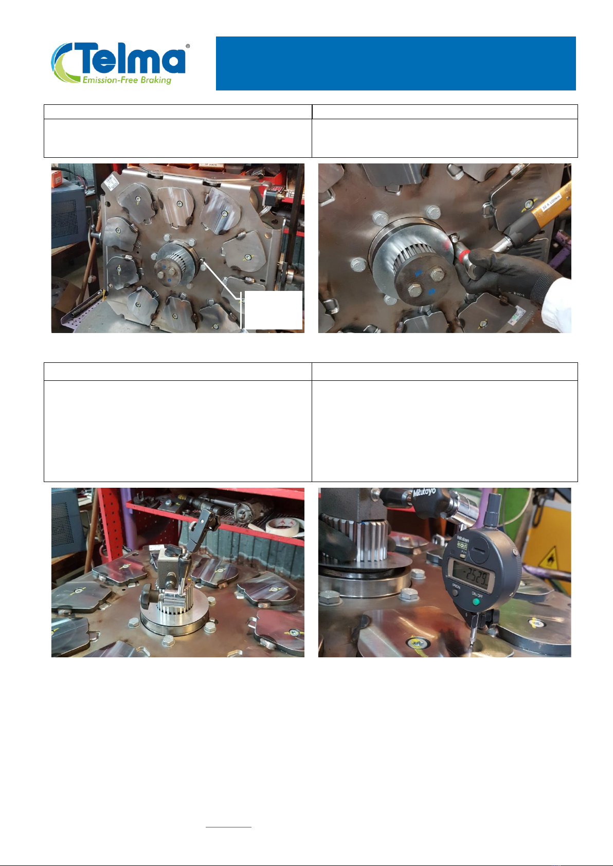
7A-15
7A-16
Toggle again the stator onto the wood blocks in
order to check the stator flatness.
Check the axial run out of the stator by using a dial
gauge with magnetic base.
Maximum allowed value: 0.40 mm
Note: in case that the measured value is above
this limit, check that no coil pressure washer is
clamped between a core and a pole shoe or
consult the TELMA technical department.
Vent
cap

MAINTENANCE MANUAL
This document is the property of Telma. It cannot be copied, forwarded, or given to any party without prior agreement form TELMA. Any infringement will immediately involve legal action.
TELMA S.A., 28 rue Paul Painlevé, F-95310 Saint-Ouen l’Aumône - www.telma.com 15 / 18 OC441691
B. INSTALLATION OF THE ROTORS
7B-1
7B-2
Lift up the stator in vertical position. On both ends
of the shaft, put in place a new black shim and
new air gap adjusting shims with a thickness to the
one removed in step 6A-7.
Note: the black “Nuflon” coated shim must be
installed first; its presence is mandatory in any case.
Put new dust shields on both shaft ends.
7B-3
7B-4
Re-install both rotor with coupling flange assemblies
on the shaft, ensuring that the marks painted on
the shaft splines and on the coupling flange splines
(refer to picture 6A-4) are aligned.
When fitting the second rotor, ensure that both
marks painted on the outer edges of the rotors are
aligned.

MAINTENANCE MANUAL
This document is the property of Telma. It cannot be copied, forwarded, or given to any party without prior agreement form TELMA. Any infringement will immediately involve legal action.
TELMA S.A., 28 rue Paul Painlevé, F-95310 Saint-Ouen l’Aumône - www.telma.com 16 / 18 OC441691
7B-5
7B-6
Re-install both removed shaft end screws with the
removed pressure plates, on both retarder sides.
Do not install lock tabs yet.
With a manual torque wrench apply a tightening
torque value of 60 Nm ± 20% (44 lb.ft ± 20%)
alternately on these 2 screws.
Use a 19mm socket and a locking bar to be
inserted inside a rotor cooling canal for preventing
rotor rotation.
7B-7
7B-8
Check the axial run out of the rotors by using a dial
gauge with magnetic base.
Maximum allowed value: 0.28mm
Note: should the measured value be higher than
0,28mm, please contact the technical department
at TELMA SA.
Measure the air gaps by using a feeler gauge.
Do not turn the rotors and measure the air gap
between the rotor and each pole shoe.
The average of these 10 values must be conform
with values mentioned in retarder technical
specifications: 1.30mm 0 -0.20 . Proceed on the
same way for both retarder side). Adjust air gap by
adding or removing air gap adjusting shims if the
value is not correct (operations 7B-1 to 7B-7).
Get closer to your TELMA agent for retarder
specifications.
For additional information related to air gap
measurement, please refer to technical
information 2006/05.

MAINTENANCE MANUAL
This document is the property of Telma. It cannot be copied, forwarded, or given to any party without prior agreement form TELMA. Any infringement will immediately involve legal action.
TELMA S.A., 28 rue Paul Painlevé, F-95310 Saint-Ouen l’Aumône - www.telma.com 17 / 18 OC441691
7B-9
7B-10
After having adjusted the air gaps, on each
retarder side, unscrew the removed shaft end
screws and the removed pressure plate.
Install 2 new shaft end screws and a new pressure
plate supplied with the replacement hub assembly.
With a manual torque wrench, apply a tightening
torque value of 60 Nm ± 20% (44 lb.ft ± 20%)
alternately on these 2 screws.
Use a locking bar to be inserted inside a rotor
cooling canal for preventing the rotation of the
rotor.
7B-11
7B-12
Insert a new lock tab in the retaining tab driver
On each retarder side, put in place the lock tab
over the screw heads and hit with a hammer.
Check that the lock tabs are well bottomed over
the shaft end screw heads.
Pressure
plate
Shaft
endnd
screws

MAINTENANCE MANUAL
This document is the property of Telma. It cannot be copied, forwarded, or given to any party without prior agreement form TELMA. Any infringement will immediately involve legal action.
TELMA S.A., 28 rue Paul Painlevé, F-95310 Saint-Ouen l’Aumône - www.telma.com 18 / 18 OC441691
8. ANNEX
A. RETARDER AIR GAP VALUES
You will find the necessary information for this equipment in the following catalogue:
OC441xxx Maintenance manual for air gap adjusting on AF8 retarders
B. TAB WASHER DRIVER to be made locally
For Axial AF8 retarder: Ø A = 75mm (2.953”)
Ø A = 24mm +0.1 0(0.945” / 0.949”)
C = 40mm ± 0.1 (1.570” / 1.579”)
Table of contents
Other Telma Industrial Equipment manuals


