Telos 2101 Series User manual

TELOS 2101 USER’S MANUAL
TELOS SERIES 2101
Advanced All Digital Multi-line Multi-studio Broadcast Telephone System
USER’S MANUAL
PART IV
Studio Interface & Additional Hybrids
V2.0d

TELOS 2101 USER’S MANUAL
PART IV
THE STUDIO INTERFACE & ADDITIONAL HYBRIDS
IV-II
TABLE OF CONTENTS
This blank page is intentional.

TELOS 2101 USER’S MANUAL
PART IV
THE STUDIO INTERFACE & ADDITIONAL HYBRIDS
IV-III
TABLE OF CONTENTS
Table of Contents Part IV
1SERIES 2101 STUDIO INTERFACE - INSTALLATION.......................................................................... 5
1.1 GETTING STARTED ..................................................................................................................................... 5
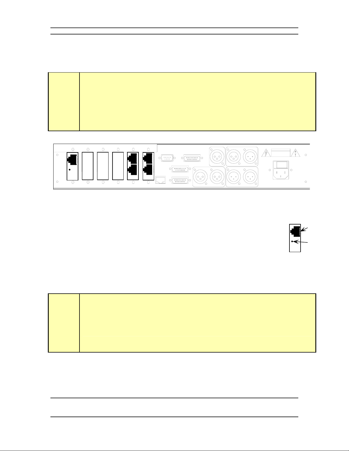
Studio Interface connections –........................................................................................................................... 6
1.2 INSTALLATION CHECKLIST (COPY THIS CHECKLIST AND USE IT TO HELP ORGANIZE YOUR INSTALLATION).................... 9
1.3 CONNECTIONS TO THE 2101 HUB AND TELOS TWO (OPTIONAL) ............................................................. 10
1.3.1 CONNECTING THE 2101 STUDIO INTERFACE TO THE 2101 HUB (STUDIO INTERFACE ONLY)............... 10
1.3.2 DESKTOP DIRECTOR™CONNECTIONS (STUDIO INTERFACE ONLY)..................................................... 13
Wiring Configurations for the Desktop Director™......................................................................................... 16
Multiple Desktop Directors on a single port ................................................................................................... 17
1.3.3 CONNECTING THE TELOS TWO TO THE STUDIO INTERFACE -THE S/T INTERFACE (TELOS TWO ONLY).. 19
1.4 STUDIO AUDIO CONNECTIONS.................................................................................................................. 21
1.4.1 MIX-MINUS.......................................................................................................................................... 21
What is a mix-minus? ...................................................................................................................................... 21
Why do I need a mix-minus?............................................................................................................................ 23
More on Mix-Minus......................................................................................................................................... 24
Phones and Remotes........................................................................................................................................ 25
1.4.2 INPUT-(TO CALLER )LEFT &RIGHT ANALOG AUDIO........................................................................... 27
1.4.3 POH (PROGRAM ON HOLD)INPUT (STUDIO INTERFACE ONLY).......................................................... 29
1.4.4 OUTPUT –(CALLER)LEFT &RIGHT AUDIO.......................................................................................... 29
1.4.5 AES/EBU DIGITAL AUDIO IN/OUT....................................................................................................... 30
1.5 AC (MAINS)POWER ................................................................................................................................. 31
1.6 REMOTE CONTROL PORTS ........................................................................................................................ 33
1.6.1 PARALLEL REMOTE CONTROL (STUDIO INTERFACE ONLY)................................................................ 33
Inputs............................................................................................................................................................... 34
Outputs ............................................................................................................................................................ 35
1.6.2 SPECIAL AUXILIARY ACCESS PORTS..................................................................................................... 36
1.6.3 RS-232 SERIAL REMOTE CONTROL...................................................................................................... 36
1.6.4 ETHERNET REMOTE CONTROL ............................................................................................................. 38
10 Base-T Ethernet Connector ........................................................................................................................ 39
2STUDIO INTERFACE CONFIGURATION.............................................................................................. 41
2.1 PRE SETUP INFORMATION ......................................................................................................................... 41
Preinstallation Work Sheet.............................................................................................................................. 41
System Programming Checklist (Copy this checklist and use it to help organize your installation) ...... 42
2.2 INITIAL INSTALLATION ............................................................................................................................. 43
2.3 TELCO SETUP ........................................................................................................................................... 43
2101 Studio Interface ...................................................................................................................................... 43
Telos TWO Hybrid........................................................................................................................................... 43
2.4 TCP/IP &HOSTNAME SETUP (STUDIO INTERFACE [REQUIRED]&TELOS TWO [OPTIONAL])............. 44
2.5 IS THIS STUDIO INTERFACE WORKING?..................................................................................................... 46
2.6 LEVELS,LEVELS,LEVELS ........................................................................................................................ 48
2.7 TIME TO TEST IT OUT!...............................................................................................................................49
What now?....................................................................................................................................................... 52
3DETAILED CONFIGURATION & REFERENCE................................................................................... 53
3.1 LEVEL METERING .................................................................................................................................... 54
3.2 STATUS DISPLAYS .................................................................................................................................... 56
3.3 ADVANCED:SETTING THE 2101 STUDIO INTERFACE’S OR TELOS TWO’S CONFIGURATION .................... 56
3.3.1 THE AUDIO MENU ................................................................................................................................57
3.3.2 THE TEL MENU .................................................................................................................................... 67

TELOS 2101 USER’S MANUAL
PART IV
THE STUDIO INTERFACE & ADDITIONAL HYBRIDS
IV-IV
TABLE OF CONTENTS
3.3.3 THE SYSTEM MENU.............................................................................................................................. 69
3.4 EXTERNAL CONTROL ............................................................................................................................... 75
3.4.1 RS-232 CONTROL................................................................................................................................. 75
Serial Port Commands (Studio Interface only)................................................................................................ 76
3.4.2 ETHERNET 10BASE-T CONTROL ........................................................................................................... 83
3.5 SYSTEM AUDIO PROCESSING AND FEEDBACK CONTROL.......................................................................... 83
3.5.1 SEND AUDIO PROCESSING .................................................................................................................... 83
3.5.2 RECEIVE (CALLER)AUDIO PROCESSING .............................................................................................. 84
3.5.3 DUPLEX “DUCKING”SYSTEM............................................................................................................... 86
3.5.4 FEEDBACK CONTROL ........................................................................................................................... 86

TELOS 2101 USER’S MANUAL
PART IV
THE STUDIO INTERFACE & ADDITIONAL HYBRIDS
IV-5
SECTION 1 – STUDIO INTERFACE INSTALLATION
1Series 2101 Studio Interface - INSTALLATION
1.1 Getting Started
If you have not done so already, you should read the material in Part I (Introduction
to the Series 2101 and its components) and Part II (Series 2101 Planning & Design).
In this section we will cover the various input/output connections of the 2101 Studio
Interface and what you need to know to install the system. Later, in section 2, we will
cover the steps necessary to configure the unit for initial operation and test it. Section
3 has a detailed reference of all menus in the Studio Interface.
The Telos Series 2101 Studio Interface mounts in a 2RU high space in a standard 19”
rack. The unit will operate in any environment where the ambient air temperature is
between 0 to 40 degrees Celsius (32 to 104 degrees Fahrenheit). and relative
humidity is between 0 to 98% (non-condensing). The unit will operate on any
commonly available AC mains voltage between 90 and 240 volts 50 – 60 Hz. You
will want to mount the unit in a position convenient for cable access for the T-Link,
Ethernet, and audio connections.
w
IMPORTANT TIP!
Please see Part II Section 1 of this manual for Series 2101 System Design Criteria. We
assume here that you are familiar with the concepts presented there.
You will need to:
•Connect the T-Link circuits from the 2101 Hub
•Connect audio, via either analog or digital (AES/EBU)
•Connect 1 or more Desktop Directors (screener phone/control surfaces)
•Connect to power
•Assign each Studio Interface a unique IP address
•Assign each Studio Interface a unique Host Name (i.e. Studio name)
•Connect to a 10/100Base-T LAN (local area network)
•Configure the hybrids’ audio characteristics for the requirements of your
installation
•Connect and configure optional Telos TWO hybrid (for studios which
require 4 hybrids)

TELOS 2101 USER’S MANUAL
PART IV
THE STUDIO INTERFACE & ADDITIONAL HYBRIDS
IV-6
SECTION 1 – STUDIO INTERFACE INSTALLATION
•Configure at least one Telco Trunk interface in the 2101 Hub and configure
the trunks associated with that digital telephone circuit.
•Configure at least one Show Configuration on the 2101 Hub
•Configure at least one Studio Configuration on the 2101 Hub including the
Show Configuration created above.
•Test to confirm proper operation
Studio Interface connections –
A “maxed out 2101 Studio Interface includes the following connections:
Î8 Desktop Directors (using optional power supplies and expansion
card)
Î2 T-Link connections to the hub(s) (using optional T-Link Studio
Interface I/O)
Î1 dual channel AES/EBU send-to-caller digital mix-minus source
OR
Î2 send-to-caller analog mix-minus source(s)
Î1 dual channel AES/EBU Caller output
AND/OR
Î2 Analog caller outputs
Î1 program on hold analog source
ÎAccessory 2101 extended dual hybrid (reduces maximum number of
Directors to 6)
Note that there are several configuration choices that you will be making in order to
install the system in a given facility. A diagram of the 2101 Studio Interface’s inputs
and outputs follows:

TELOS 2101 USER’S MANUAL
PART IV
THE STUDIO INTERFACE & ADDITIONAL HYBRIDS
IV-7
SECTION 1 – STUDIO INTERFACE INSTALLATION
Rear Panel of the 2101 Studio Interface illustrating the various connectors.
Note: The stock Studio Interface includes a single T-Link Interface and a single Desktop
Director Interface. Both AES/EBU and analog outputs are simultaneously active.
1 0
1212
ABC DEF
RS-232 (DCE)
10 Base-T
SAA 1
SAA 2
Parallel Remote
POH AES/EBU
IN OUT
IN
1122
T-Link Port
Connects to
2101 Hub
Desktop Director Ports
Each port supports two
Desktop Directors for a
total of four. If more
than two Directors (total)
are to be used a Desktop
Director Power Supply Kit
(Part # 0212-1400) must
be used
Additional Desktop
Director Ports
(Optional)
Part # 2001-00022
allows connection of four
additional Directors for
a ma x imum o f e ig ht .
External Power Supply
Required.
Parallel Po rt
Control Inputs
(Such as Ring-
mute) & Outputs
T-Link
LOS ALARM
(LED illuminates
if T-Link is lost)
10 Base-T
Ethernet
A LAN Connection
is required
INPUT(Send to Caller OUTPUT (Caller)
Inp ut - Sen d
t o C aller
Hybrids 1 & 2
(Analog)
-7 to +4 (nom)
Output -
Fro m c aller
Hybrids 1 & 2
(Analog)
-7 to +8 (nom)
IEC Main s
Power Jack
100-240 VAC
50/60 Hz
Power
Switch
AES/EBU
Output -
Fro m C aller
Dual format
signal with
Hybrid 1 on
Left & Hybrid 2
on Right
Program
on Hold
Inp ut
(Analog)
+4 (nom)
AES/EBU
Inp ut -
Sen d To C aller
Dual format
signal with
Hybrid 1 on
Left & Hybrid 2
on Right
Second T-Link
Card should be
inserted here
when configuring
dual redundant
systems.

TELOS 2101 USER’S MANUAL
PART IV
THE STUDIO INTERFACE & ADDITIONAL HYBRIDS
IV-8
SECTION 1 – STUDIO INTERFACE INSTALLATION
CONTROL
BLOCK
INTEGRAL
TELOS
TWO
HYBRID
T-LINK
INTERFACE
&
MATRIX
BLOCK
2101 Studio Interface
SEND
to Caller
(AES)
1&2
SEND
to Caller
(Analog)
1
SEND
to Caller
(Analog)
2
CALLER
Out
(Analog)
1
CALLER
Out
(Analog)
2
CALLER
Out
(AES)
1&2
Ethernet 10 base-T WAN/LAN
Connection
Program
on Hold
Source KEY
Data
T-LINK
A
nalog Audio
A
ES/EBU Audio
Parallel Outputs (Status &
Control) and Remote control
To
2101
Hub
The input & output ports of the 2101 Studio Interface.
Note that the system can support up to Eight Desktop Directors™; Only one of the input
options (AES/EBU or Analog) can be selected at a given time;

TELOS 2101 USER’S MANUAL
PART IV
THE STUDIO INTERFACE & ADDITIONAL HYBRIDS
IV-9
SECTION 1 – STUDIO INTERFACE INSTALLATION
1.2 Installation checklist (Copy this checklist and use it to help organize your installation)
We suggest you look through the rest of section 1 before proceeding. Then work
through this checklist as you prepare to install each 2101 Studio Interface.
Bring cable for T-Link circuit(s) from the location 2101 hub to the location of
the 2101 Studio Interface. This requires 2 pair for each T-Link connection. See
section 1.3.1 for details.
How many mix-minuses (with send-to-caller audio) will be used for this Studio
2 1 Interface? See “Routing” in section 3.3.1 for more on mix-minuses.
ÈÆIf only a single mix-minus will be available, see “Routing” in section 3.3.1.
Bring 1 or 2 mix-minus audio feeds (AES/EBU, or –7 to +4 dBu analog) from
your console to the 2101 Studio Interface.
How many inputs on the console will be used?
2 1
ÈÆIf only a single feed from the 2101 Studio Interface to the console will be
used see “Routing” in section 3.3.1 for information on your options.
Bring 1 or 2 of the Output (Caller) signals from the 2101 Studio Interface to
Èyour console.
Run one of the supplied Desktop Director cables from the 2101 Studio
Interface to each of the locations where the Desktop Directors will be located.
See section 1.3.2.
If more than two Desktop Directors will be used see section 1.3.2.
If any Desktop Director will be more than 250 feet (75 meters) from the Studio
Interface see section 1.3.2.
Run a connection from the 10/100Base-T Ethernet hub to be used for the Series
2101 to the 10Base-T connector of the Studio Interface.
If you will be using any of the 2101 Studio Interface’s remote input/output
options (such as the ringer mute input) to control the unit see section 1.6.1 and
make those connections now.
Proceed to System Programming Checklist in section 2.1.

TELOS 2101 USER’S MANUAL
PART IV
THE STUDIO INTERFACE & ADDITIONAL HYBRIDS
IV-10
SECTION 1 – STUDIO INTERFACE INSTALLATION
T-Link
Port
T-Link
LOS
LED
1.3 Connections to the 2101 Hub and Extended Hybrid (Telos TWO)
w
IMPORTANT!
Unless otherwise indicated the following instructions apply to both the Series 2101 Studio
Interface and the Telos Extended dual hybrid (Telos TWO Hybrid with special 2101
software). Additional information on the Telos TWO is included in the manual shipped
with that product.
1.3.1 Connecting the 2101 Studio Interface to the 2101 Hub (Studio Interface only)
The 2101 Studio Interface uses internal plug-in T-Link module(s) to connect to
the 2101 Hub. These module(s) have a modular jack accessible through each
rear slot, in slots A (or optionally, A& B). This will be a 8 position “RJ-45”
style miniature connector. An amber (yellow) LED next to below this connector
indicates a Loss Of Signal (LOS) and should not be illuminated under normal
circumstances.
The Studio Interface ships with a single module in slot A, if you are building a
redundant system you will need to add a second module (Telos Part # 1701-00048).
Section 4 has information on installing or replacing these modules.
w
IMPORTANT!
Your T- Link connection(s) are in the first 2 Interface slots from the left side of the unit as
viewed from the rear of the unit (slots A, and optionally, B). The RJ- 45 style connectors to
the right side (slots E & F) are for the Desktop Directors.
1 0
1212
ABC DEF
RS-232 (DCE)
10 Base-T
SAA 1
SAA 2
P a ra lle l Re m ote
POH AES/EBU
IN OUTIN
1122
IN P U T- Se nd to Ca lle r OU TP U T- Ca ller

TELOS 2101 USER’S MANUAL
PART IV
THE STUDIO INTERFACE & ADDITIONAL HYBRIDS
IV-11
SECTION 1 – STUDIO INTERFACE INSTALLATION
T-Link interface connector – Studio Interface
PIN FUNCTION
1 R1 (Receive/Input)
2 T1 (Receive/Input)
3 Not Connected
4 R (Transmit/Output)
5 T (Transmit/Output)
6 Not Connected
7 Not Connected
8 Not Connected
The T-Link interface is a standard modular RJ-45 style jack with the pin-out shown above.
Pin 1 is at the top of the T-Link jack.
w
IMPORTANT!
As with any piece of modern electronic gear, it is advisable that precautions be taken to
prevent damage caused by power surges. Special “T1” interface surge protectors can be used
to offer some degree of protection at the T- Link interface jack. If the T- Link connection will
run between two buildings this protection is required. It is the user’s responsibility to ensure
that adequate protection is provided.
e
IMPORTANT!
Be very careful to label wiring used with RJ- style connectors. In some cases they have power
on them, and there is a risk of applying this power to something which does not expect it.
For this reason we suggest that you use different colored cables (or connector boots) on the
Desktop Director cables versus your Ethernet, T- Link, & other Cables.

TELOS 2101 USER’S MANUAL
PART IV
THE STUDIO INTERFACE & ADDITIONAL HYBRIDS
IV-12
SECTION 1 – STUDIO INTERFACE INSTALLATION
T-Link interface cable (for use with Rev B T-Link card in the 2101 Hub)
T-Link Interface cable.
Note: Pin 1 is to the left when viewed as above (with pins facing you and at the top).
PIN COLOR
1 White/Green
2 Green
3* White/Orange
4 Blue
5 White/Blue
6* Orange
7* White/Brown
8* Brown
* = Not required
The T-Link connection can be made using a standard EIA/TIA-568-A T568A category 5
cable. Optionally, the cable can be wired with only two pairs as indicated above. The
above “straight through” wiring is applicable to the 2101 Hub Interface version B only.

TELOS 2101 USER’S MANUAL
PART IV
THE STUDIO INTERFACE & ADDITIONAL HYBRIDS
IV-13
SECTION 1 – STUDIO INTERFACE INSTALLATION
T-Link interface crossover cable (for use with Rev A T-Link card in the 2101
Hub)
PIN COLOR DIRECTION PIN
1 White/Green Å4
2 Green Å5
3* White/Orange 3*
4 Blue Æ1
5 White/Blue Æ2
6* Orange 6*
7* White/Brown 7*
8* Brown 8*
* Not used on the T- Link Interface
T-Link cable wiring diagram. Note that this is a special cable and both ends are not wired
identically. Note that the T-Link interface does not require all 8 conductors. This “crossover cable”
is for use only when Rev A T-Link cards are used in the 2101 Hub.
h
HOT TIP!
This cable must be fabricated on site and is not included with the Series 2101. Note
that this is not the same as an Ethernet “Crossover” cable.
1.3.2 Desktop Director™ Connections (Studio Interface only)
The 2101 Studio Interface has 2 Desktop Director™ ports located in slots F. Each
port supports 1 Desktop Director™ directly. The internal power supply of the Studio
Interface can power up to two (2) 12 line Desktop Directors without the need of an
external power supply. A second Desktop Director can be added to each port (for a
total of 4) using a Desktop Director Power Supply Kit (Telos part # 2001-00024)
available from your Telos Dealer. Each Power Supply kit allows one additional
Desktop Director. An expander kit is also required for any Desktop Director located
more than 250 feet (75 meters) from the Studio Interface. One Power Supply Kit is
required for each two Desktop Directors added in excess of two.
An additional two Desktop Director ports may be added by installing an optional
second Desktop Director Interface card (Telos part # 2001-00022). See section 4 for

TELOS 2101 USER’S MANUAL
PART IV
THE STUDIO INTERFACE & ADDITIONAL HYBRIDS
IV-14
SECTION 1 – STUDIO INTERFACE INSTALLATION
instructions on installing this card.
Note that the Expanded Desktop Director (for use with 24 Lines or 4 hybrids)
requires a Desktop Director Power Supply Kit (Telos part # 20001-00024).
A Desktop Director port is also used to connect the optional Telos TWO dual hybrid.
This reduces the allowable number of Desktop Directors by two. See section 1.3.3 for
information on connecting the Telos TWO to your Studio Interface.
Jack on Desktop Director™
PIN FUNCTION
1 Not used
2 Not used
3 S Transmit to Studio Interface +
4 S Receive from Studio Interface +
5 S Receive from Studio Interface -
6 S Transmit to Studio Interface -
7* Power Sink –
8* Power Sink + (Top)
The interface connector on the Desktop Director™ is a standard modular RJ-45 style jack.
e
IMPORTANT!
Be very careful to label wiring used with RJ- style connectors. In some cases they have power
on them, and there is a risk of applying this power to something which does not expect it.
For this reason we suggest that you use different colored cables (or connector boots) on the
Desktop Director cables versus your Ethernet, T- Link, & other Cables.
t
DEEP TECH NOTE!
If the above wiring table looks familiar to you, that’s not surprising, this looks just like the
ISDN S interface on any piece of ISDN terminal gear! That’s not a coincidence, our work
with ISDN led to using this robust interface for other purposes as you see here.

TELOS 2101 USER’S MANUAL
PART IV
THE STUDIO INTERFACE & ADDITIONAL HYBRIDS
IV-15
SECTION 1 – STUDIO INTERFACE INSTALLATION
Desktop
Director
Ports
2101 STUDIO INTERFACE Desktop Director™ Ports (interface slots E (optional)
& F)
PIN FUNCTION
1 Not used
2 Not used
3 S Receive from Director +
4 S Transmit to Director +
5 S Transmit to Director -
6 S Receive from Director -
7 PS2 Power Source -
8 PS2 Power Source +
The 2101 Studio Interface has 2 Desktop Director™ ports in Interface slots F. Optionally a
second card can be installed in slot E. Pin 1 is at the top. Power is provided on pins 7 & 8 for
a maximum of two Desktop Directors. If more than one Desktop Director™ is required on a
single port an external power supply will be required (see below)
This interface is a standard 8-position/8-pin miniature modular jack
(RJ-45 style) and has the data pairs exchanged as compared to an
ISDN S interface on an NT1, or the Desktop Director. Therefore a
“straight through” (non-crossover) cable is used between the 2101
Studio Interface and the Desktop Director as follows.
Desktop Director™ Cable
Note: Pin 1 is to the left when viewed as above (with pins facing you and at
the top).

TELOS 2101 USER’S MANUAL
PART IV
THE STUDIO INTERFACE & ADDITIONAL HYBRIDS
IV-16
SECTION 1 – STUDIO INTERFACE INSTALLATION
PIN COLOUR DESCRIPTION
1 White/Green Not used
2 Green Not used
3 White/Orange Xmt (TE to NT) to Network +
4 Blue Rcv (NT to TE) from Network +
5 White/Blue Rcv (NT to TE) from Network -
6 Orange Xmt (TE to NT) to Network -
7 White/Brown PS 2 Power - 48 VDC
8 Brown PS 2 Power ground (+)
Desktop Director™ cable wiring diagram. TIA 568A or 568B standard
Category 5 cables may be used. Both ends should be wired identically.
The signal to the Desktop Director™ is electrically similar to the ISDN S interface.
This connection is limited to 2300 Feet (700 meters) and wiring should be configured
using the extended passive bus configuration (see below for some examples).
h
HOT TIP!
Since category 5 wire is so common (and prices have dropped) we recommend that you use it
instead of category 3 wire for the ISDN, Ethernet, and Desktop Director™ wiring.
Wiring Configurations for the Desktop Director™
Each Desktop Director™ is supplied with a 25-foot cable which is used to make this
connection. You can make your own cables as long as they follow the wiring shown
above. Category 3 type (Cat. 3) or higher cable must be used; we suggest Category 5
type (Cat. 5) wire. The usual configuration of two Desktop Directors involves merely
plugging in this supplied cable to the Director and 2101 Studio Interface as illustrated
below:

TELOS 2101 USER’S MANUAL
PART IV
THE STUDIO INTERFACE & ADDITIONAL HYBRIDS
IV-17
SECTION 1 – STUDIO INTERFACE INSTALLATION
To Studio Interface
Desktop Director Port
250 feet (76 meters) maximum
The basic Desktop Director™ configuration is simple and straightforward.
If the Desktop Director™ must be located more than 250 feet (76 Meters) from the
2101 Studio Interface you will need to use a local power supply (Desktop Director
Power Supply Kit part # 2001-00024) to supply power to it. In that case, your
configuration will look like the following:
To Studio Interface
Desktop Director Port
250 feet (75 meters) maximum 2050 feet (625 meters)
i
Power
Supply
In the extended configuration the Desktop Director™ must be within 2300 feet (700 meters) of the
2101 Studio Interface. The power supply must be 250 feet (76 Meters) or less from the Desktop
Director.
Multiple Desktop Directors on a single port
This connection option is similar to the preceding, and allows two Desktop Directors
to be connected to a single Desktop Director™ port of the Studio Interface (allowing
for 8 Desktop Directors total). To do so you will need to use a local power supply
and modular splitter (Desktop Director™ Power Supply Kit part # 2001-00024) to
connect it. There are two reasons you might wish to do this. If you need to connect
more than two Desktop Directors you would have to use this method. Or, you might
choose this method to save on cable runs back to a Studio Interface located some
distance away.

TELOS 2101 USER’S MANUAL
PART IV
THE STUDIO INTERFACE & ADDITIONAL HYBRIDS
IV-18
SECTION 1 – STUDIO INTERFACE INSTALLATION
To Studio Interface
Desktop Director Port
1100 feet (338 meters) maximum
Power
Supply
Distance "A"
Distance "B"
NOTES:
1) A must be less than 120 feet (37 meters)
2) B must be less than 33 feet (10 meters)
3) Desktop Director B must have termination
resistors removed.
8-Pin (RJ-45)
Modular splitter
(Included w/
power supply)
In the Multiple configuration one Desktop Director™ must be reconfigured to have its termination
resistors removed (see below). This unterminated Desktop Director™ must be within 33 feet (10
meters) of the power supply
Desktop Director™ Termination Resistor Settings
Desktop Directors™ are shipped with the internal termination resistors enabled.
When two Desktop Directors are used in a single port, the termination resistors on the
Director closer to the power supply will need to be disabled. To do so follow the
steps below:
1. Disconnect the Desktop Director cable from the Desktop Director.
2. Remove the handset from its resting place and turn over the Director so you
can see the bottom of the unit.
3. Remove the round black cover. This can be pried off with a knife blade. Or a
miniature screwdriver may be pushed firmly under the lip and then lifted
out to pop the cap loose.
4. You will see a black rectangular transformer labeled T1. To the right of T1
locate and remove the jumpers labeled JP1 & JP2.
These are small jumper blocks that can be lifted off with needle- nose pliers.
5. You’ll want to save the jumper blocks. You can store each of them on one of
the jumper pins.
6. Replace the access cover removed in step 3 by pushing firmly in place.

TELOS 2101 USER’S MANUAL
PART IV
THE STUDIO INTERFACE & ADDITIONAL HYBRIDS
IV-19
SECTION 1 – STUDIO INTERFACE INSTALLATION
7. Reconnect the Desktop Director cable and turn the unit upright
8. Check for proper operation
1.3.3 Connecting the Telos TWO to the Studio Interface - The S/T Interface (Telos
TWO only)
When connecting to the Series 2101 Studio Interface you will be using the 8-
position/8-pin miniature modular (RJ-45 style) jack on the back of the TWO. Most
units will have two modular jacks. This will be the lower (and smaller) of the two
jacks. If a single jack is present you will use that jack.
You will be using a modular cable to connect from this jack to one of the Desktop
Director ports of the Series 2101 Studio Interface. The cable used is the same cable
used with the ISDN “S interface”. See below for a diagram of the basic hookup.
U
S/T
NT1 TA
TWO USA ISDN Interface
Desktop Director port on
Series 2101 Studio Interface.
U (Line Direct)
jack not used, if
present.
Diagram of the connection of a Telos TWO to a Studio Interface.
The TWO uses both Channels of the Desktop Director port so the
port used cannot be shared with a Desktop Director.
The S/T cable has wider plugs than a normal telephone cable, using 8-position/8-pin
(RJ-45 style) miniature modular connectors. Four of the wires are used for the S
interface and two are used to convey power (these are not needed in this application).
Unshielded twisted pair category 3 (or higher) cable should be used. The cable details
are shown below:

TELOS 2101 USER’S MANUAL
PART IV
THE STUDIO INTERFACE & ADDITIONAL HYBRIDS
IV-20
SECTION 1 – STUDIO INTERFACE INSTALLATION
BRI S Interface cable.
Note: Pin 1 is to the left when viewed as above (with pins facing you and at the top).
PIN COLOR DESCRIPTION
1* White/Green PS 3 Power +/ground (Optional)
2* Green PS 3 Power – (Optional)
3 White/Orange Xmt (TE to NT1) to Network +
4 Blue Rcv (NT1 to TE) from Network +
5 White/Blue Rcv (NT1 to TE) from Network -
6 Orange Xmt (TE to NT1) to Network -
7@ White/Brown PS 2 Power 48 VDC -
8@ Brown PS 2 Power +/ground
*
@
Not used on Telos TWO
Used only in units shipped to the USA & Canada.
Not needed when connecting to Studio Interface
ISDN S interface cable wiring diagram. Both ends are wired identically.
h
HOT TIP!
This cable has 4 twisted pairs wired “straight through” just like the cable normally
used for Ethernet 10 Base- T. The wiring configuration is the same as TIA/E- 568- A
T568A (T568B is electrically equivalent).
The outside pairs (Brown and Green) are often not required and may be omitted.
Other manuals for 2101 Series
1
Table of contents
Other Telos Telephone System manuals