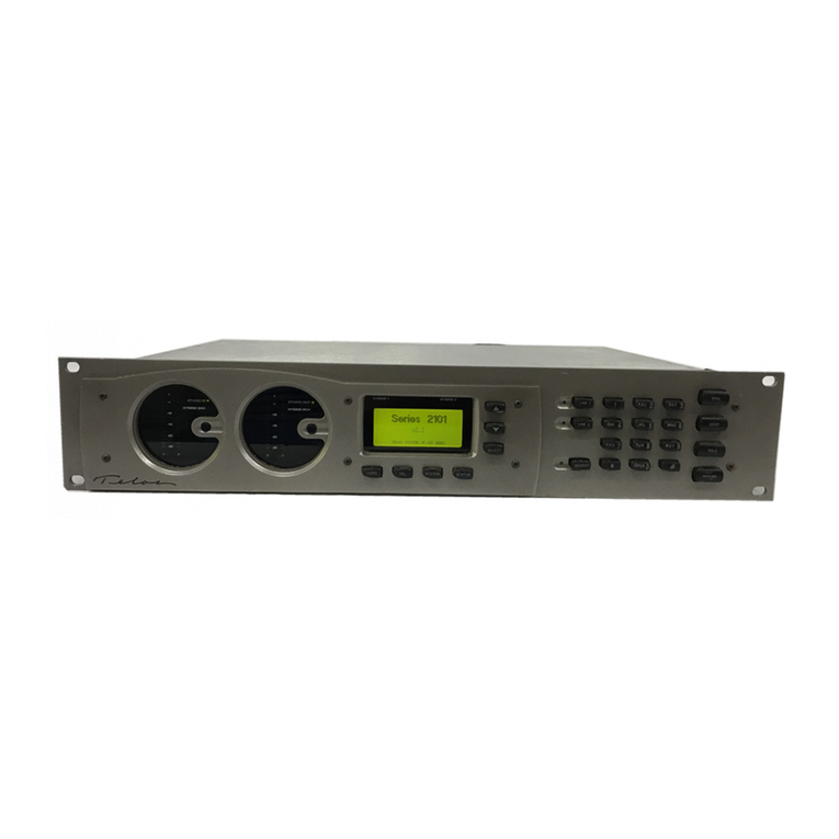
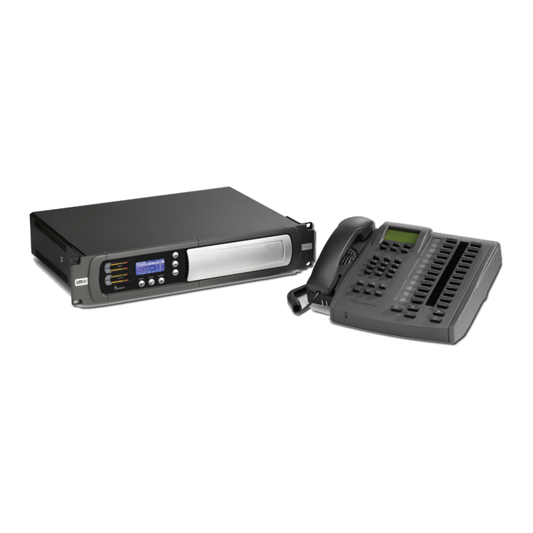
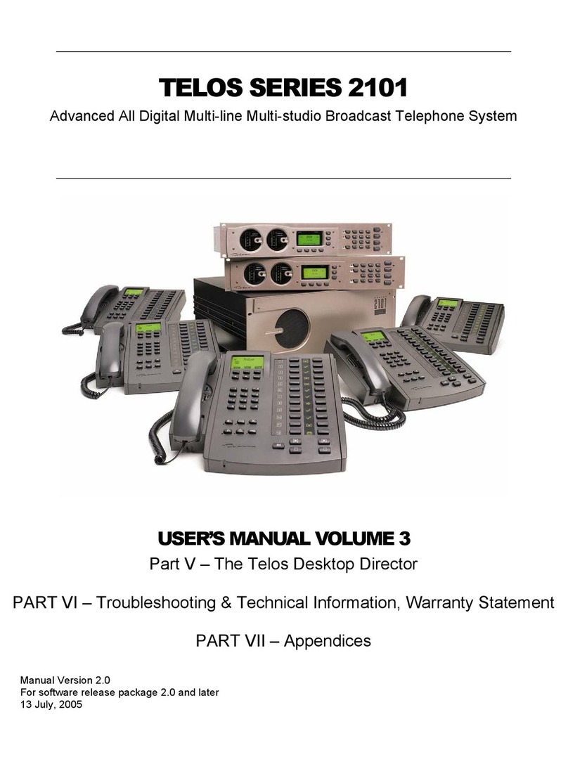
Telos 2101 Series User manual

TELOS SERIES 2101
AdvancedAll Digital Multi-line Multi-studio Broadcast Telephone System
USER’S MANUAL VOLUME 2
PART III – The Series 2101 Hub
PART IV – Series 2101 Studio Interface
Manual Version 2.0
For software release package 2.0 and later
22 July, 2005


TELOS SERIES 2101
Advanced All Digital Multi-line Multi-studio Broadcast Telephone
System
PART III
The Series 2101 Hub
V 2.0

TELOS 2101 USER’S MANUAL
This Page Intentionally Left Devoid of Useful Information

TELOS 2101 USER’S MANUAL
Tables of contents Part III
1INTRODUCTION – WHAT IS THE SERIES 2101 HUB?.............................................................. 1
2PREPARING THE HUB FOR INSTALLATION............................................................................. 5
2.1 INSTALLING INTERFACE CARDS IN THE HUB ................................................................................... 5
Identifying the Cards .................................................................................................................................. 5
Installing cards in the Hub ......................................................................................................................... 8
3INSTALLING THE SERIES 2101 HUB.......................................................................................... 11
3.1 CONNECTING IT UP ........................................................................................................................ 11
3.1.1 A NOTE ON REBOOTING THE 2101 HUB...................................................................................... 11
3.1.2 TELCO TRUNK CONNECTIONS ................................................................................................... 11
3.1.3 THE T-LINK CONNECTIONS TO THE STUDIO INTERFACES.......................................................... 14
3.1.4 ETHERNET 10/100 BASE-T CONNECTION TO THE LAN ............................................................. 17
3.1.5 AC MAINS POWER,OPERATING ENVIRONMENT........................................................................ 18
AC (mains) Power..................................................................................................................................... 18
Environmental Considerations ................................................................................................................. 20
4THE 2101 HUB WEB CONFIGURATION PAGES....................................................................... 21
4.1 ADMINISTRATION PC REQUIREMENTS: ......................................................................................... 21
4.2 ACCESSING THE 2101 HUB WEB CONFIGURATION PAGES............................................................... 21
4.2.1 LOGGING IN TO 2101................................................................................................................. 24
4.3 SYSTEM OPTIONS MENU (HUB CONFIGURATION)......................................................................... 25
4.4 LINE STATUS................................................................................................................................. 27
4.4.1 Configuring the Telco Trunk Ports........................................................................................... 27
Configuring the Telco Trunk Hardware & Protocol Settings................................................................... 28
4.4.2 Configuring your Telco Trunks ............................................................................................ 32
Entering the trunk information ................................................................................................................. 34
Checking your port & trunk configuration ............................................................................................... 34
4.5 SHOW CONFIGURATION................................................................................................................. 35
Creating Show Configurations.................................................................................................................. 36
4.6 CREATING STUDIO CONFIGURATIONS .......................................................................................... 39
4.7 USING THE USER MANAGER.......................................................................................................... 41
4.8 SYSTEM SECURITY TO RESTRICT 2101 HUB ACCESS...................................................................... 42
4.9 SOFTWARE UPDATE ...................................................................................................................... 43
4.10 CONFIGURATION MANAGEMENT................................................................................................... 44
4.11 ABOUT THE WEB CONFIGURATION UTILITY.................................................................................. 45
4.12 2101HUB WEB CONFIGURATION UTILITY ERROR MESSAGES....................................................... 45
PART III
THE SERIES 2101 HUB
TABLE OF CONTENTS
III-iii

TELOS 2101 USER’S MANUAL
This page intentionally left blank, except for this message, of course.

TELOS 2101 USER’S MANUAL
1Introduction – What is the Series 2101 Hub?
The 2101 Hub is a highly specialized microprocessor-controlled telephone switch,
optimized for easy management and flexible control. It supports up to two Telco
Trunk Interfaces cards to connect to the digital trunks from your telephone company.
Each Telco interface supports one or two Telco circuits, for a total capacity of up to
four circuits. The 2101 hub also has up to 32 T-Link interface ports that are the “Line
side” interface from the System Hub to the 2101 Studio Interface(s) and Desktop
Directors™. Each Studio Interface acts similarly to a “Key” telephone system, with
12-24 “lines” coming from the Hub.
A significant feature of the system hub is the fact that it can be easily configured with
a number of Show Configurations. Each Show Configuration assigns a specific group
of “line appearances” to a specific Studio Interface. Lines may be shared among one
or more Show Configurations, if desired.
An IP (Internet Protocol) connection over 10/100 Base-T Ethernet allows
communication directly between the 2101 Hub and the Studio Interfaces to
accomplish coordination and control.
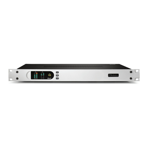
Series 2101 Hub, front panel
w
IMPORTANT SAFETY NOTICE!
Before connecting AC Mains power, you must check the power supply
voltage select switches. You must loosen the small knurled knob and
open the power supply compartment to expose the two power supplies.
Each power supply has a voltage select switch that can be set to either
120 Volts AC or 240 volts AC. e
PART III
SERIES 2101 HUB
III-1
SECTION 1 – INTRODUCTION: WHAT IS THE SERIES 2101 HUB?

TELOS 2101 USER’S MANUAL
B RUN
A FAIL
PORT A
PORT B
B RUN
A FAIL
PORT A
PORT B
T-Link Hub I/O Card
At least one is required.
Connects to Studio Interface
Allports are equivalent (any
port may be connected to
any studio interface.
Ethernet
100 Base-T
Network
Connection
Connects to an
Ethernet 10/100
Base-T Hub.
DualTelco
Trunk
Interfaces
Connects to
NCTE (CSU).
Available in both
Single and Dual
versions. At
least one Telco
Trunk Interface
is required.
IEC Mains
Power Jack
120 or 220 volts
AC (Switchable)
50/60 Hz.
Power Switch is
on front of unit.
Power Alarm
Reset Switch
If a redundant
supply power
ceases operation,
an alarm will sound.
Press this button to
reset the alarm.
DualRedundant
Power Supplies
Loosen the two
knurled screws and
swing up to open.
The Series 2101 Hub rear panel. CPU/Ethernet cards may vary. Locations of cards In slots
may vary. The connectors covered by “hash marks” are not used.
Models with the dual redundant power supply will have a door near the power jack. Inside
this door are the two power supplies. Make sure to check the voltage settings on both of
these power supplies.
The Telos 2101 Hub Configuration Web Pages are used to configure the Hub and
create Show Configurations. See Section 4 for details on this.
As you will recall from Part II of this manual, the hub connects to each 2101 studio
interface, as illustrated on the next page.
PART III
THE SERIES 2101 HUB
III-2
SECTION 1 – INTRODUCTION: WHAT IS THE SERIES 2101 HUB?

TELOS 2101 USER’S MANUAL
PART III
SERIES 2101 HUB
III-3
SECTION 1 – INTRODUCTION: WHAT IS THE SERIES 2101 HUB?
Telos
Telos
Telos
Telos
Ethernet 10/100 Base-T Hub
Telos
Telos System 2101
Typical System Configuration
Note, 2 more Desktop Directors per Studio are
supported using Part # 2001-00024 Power
Supply. A total of 8 Desktop Directors per Studio
supported using 3 Part # 2001-00024 plus Part #
2001-00022 Dual Desktop Director Interface Card.
Ethernet
10Base-T
Studio 1
Studio 2
Studio 3
Studio 4
Studio 32
Hybrids 1&2 Out
(Analog orAES)
Series 2101 Hub
Send to Caller in
1&2(analog orAES)
&Programon Hold in
Telos T-Link Protocol
(2 Pair)
Ethernet
100 Base-T
Hybrids 1&2 Out
(Analog or AES)
Send to Caller in
1&2(analog orAES)
&Programon Hold in
Send to Caller in
1&2(analog orAES)
&Programon Hold in
Hybrids 1&2 Out
(Analog or AES)
Send to Caller in
1&2(analog orAES)
&Programon Hold in
Hybrids 1&2 Out
(Analog or AES)
Hybrids 1&2 Out
(Analog or AES)
Send to Caller in
1&2(analog orAES)
&Programon Hold in
PSTN
NCTE
(CSU)

TELOS 2101 USER’S MANUAL
This page was left blank intentionally. However, if you find this upsetting or
inconvenient you may write some notes or pictures here.
PART III
THE SERIES 2101 HUB
III-4
SECTION 1 – INTRODUCTION: WHAT IS THE SERIES 2101 HUB?

TELOS 2101 USER’S MANUAL
2Preparing the Hub for Installation
The 2101 Hub requires at least one Telco Trunk Interface and at least one T-Link
Interface. Together with your Sales Engineer, you will have determined which
components are needed for your situation. The first thing you will need to do is to
install those components.
2.1 Installing Interface Cards in the Hub
Identifying the Cards
You will need to install various interface cards in your system. As description of each
the various cards is included in the following table:
2101 Hub Interface Cards
Telos Part
Number
Description Max # in
System
Notes:
1701-00049 T-Link Hub I/O Card 8 Has 4 ports for connection to Series 2101
Studio Interfaces. May be installed in slots 1-8
2091-00013 PRI/T1 Telco Interface Supports a single T1 connection or 23B+D PRI
connection (1.544 Mbps) as used in North
America. May be installed in slots 10&11
2091-00014 Dual PRI/T1 Telco
Interface
2
Cards
may be
mixed.
Supports two T1 connections or 23B+D PRI
connections (2 x 1.544 Mbps) as used in North
America. May be installed in slots 10&11
2091-00015 PRI/E1 Telco Interface Supports a single E1 connection or 30B+D PRI
connection (2.048 Mbps) as used in Europe.
May be installed in slots 10&11
2091-00016 Dual PRI/E1 Telco
Interface
2
Cards
may be
mixed.
Supports 2 E1 connections or 30B+D PRI
connections (2 x 2.048 Mbps) as used in
Europe. May be installed in slots 10&11
You can identify these cards by looking at the face plate and connectors. The
different types of cards are pictured below:
PART III
SERIES 2101 HUB
III-5
SECTION 2 – PREPARING THE HUB FOR INSTALLATION

TELOS 2101 USER’S MANUAL
The T-Link Hub I/O Card, Rev B Style.
Each card supports connections for up to four Studio Interfaces. The system manages the
T-Link connections and any port can be used for any Studio Interface.
The four amber LEDs at the bottom indicate “Loss of Signal” and should be extinguished if
a Studio Interface is present and active. The top LED corresponds to the top T-Link port
and so forth.
The T-Link Hub I/O Card, Rev A style.
Each card supports connections for up to four Studio Interfaces. The system manages the
T-Link connections and any port can be used for any Studio Interface.
The four amber LEDs at the top indicate “Loss of Signal” and should be extinguished if a
Studio Interface is present and active. The top LED corresponds to the top T-Link port and
so forth.
NOTE: The Rev A version requires a custom “Crossover Cable” to connect to the
Studio Interface. See Appendix 3.
PART III
THE SERIES 2101 HUB
III-6
SECTION 2 – PREPARING THE HUB FOR INSTALLATION

TELOS 2101 USER’S MANUAL
B RUN
A FAIL
B
A
The Dual Telco Interface Card.
The single Interface card is the same but only has one port.
If only one port is to be used, you must use Port A (lower port). Pin 1 is at the top.
The two amber LEDs to the left indicate “Loss of Signal” on Port A or B and should be
extinguished if an active line is present. See the table below for additional information on
the diagnostic LEDs.
NAME COLOR INDICATES
Run Green Off = Board Not Running
On = Normal Activity
Fail Amber
(Yellow)
Off = Normal Operation
On = Telco Interface Board failure
B (LOS) Amber
(Yellow)
Off = Normal Operation
On = Loss Of Signal (carrier failure, Red Alarm or
Yellow Alarm) on B
A (LOS) Amber
(Yellow)
Off = Normal Operation
On = Loss Of Signal (carrier failure, Red Alarm or
Yellow Alarm) on A
Diagnostic LED interpretation for the Telco Trunk Interface Cards
PART III
SERIES 2101 HUB
III-7
SECTION 2 – PREPARING THE HUB FOR INSTALLATION

TELOS 2101 USER’S MANUAL
Installing cards in the Hub
The Series 2101 Hub has slots 14 slots. We shall refer to them as slots one through
fourteen left to right as viewed from the rear of the Hub. Note however, the slots are
not numbered on the chassis of the unit.
B RUN
A FAIL
PORT A
PORT B
B RUN
A FAIL
PORT A
PORT B
Rear view of the Series 2101 Hub fully populated. Note the T-Link Studio I/O Cards in Slots
One through Eight and the Telco Interface Cards in Slots Ten & Eleven. Position of cards
may vary depending on number of Telco cards Installed.
w
IMPORTANT!
1) Slots 13 & 14 must remain unused.
2) Slots 1, 2, 3, 4, 5, 6, 7, 8 (sometimes 9) are for use with T- Link Hub I/O cards only.
3) Slots 9 & 10 or 10 & 11 are for use with Telco Trunk Interface cards.
4) Slot 12 is reserved for the Processor/100 Base- T Card (Provided with Hub).
Follow these steps to install a card in the 2101 Hub:
w
IMPORTANT!
•The following instructions are to be followed by qualified Technical Personnel
ONLY.
•Handling appropriate for Static Sensitive Electronic Devices (such as personnel
grounding straps) must be employed whenever the Hub is open. Damage caused
by a failure to do so is not covered by the equipment Warranty.
PART III
THE SERIES 2101 HUB
III-8
SECTION 2 – PREPARING THE HUB FOR INSTALLATION

TELOS 2101 USER’S MANUAL
1. Disconnect the power cable and any other cables present from the Hub.
2. Remove the four Phillips- head screws that hold the top cover in place (two
on each side of the Hub).
3. Lift the cover straight up and set aside.
4. Determine the correct slot for the card(s) to be installed (See above).
5. Remove the blank Slot Cover- plate from the slot(s) to be populated by
removing a single Phillip- head screw located at the top of the Slot Cover-
plate. Remove the blank Slot Cover- plate by lifting it straight up.
6. Remove the multi- conductor ribbon cable connector plugs from as many
of the existing cards as necessary to allow access to install the new card(s).
7. Align the card(s) to be installed with the socket on the main board and the
opening in the rear panel of the chassis. Seat the board in place by pushing
firmly straight down. If the board fails to seat properly lift it straight up and
out and try again.
8. Reconnect the ribbon cable connectors to each of the cards disconnected in
step 6 as well as the newly installed card(s).
9. Using the screw(s) remove in step 5 (above) fasten the card(s) in place.
10. Replace the cover on the Hub and fasten with the four screws removed in
step 2 (above).
w
WARNINGS!
- The interface cards and blank cover- plates in the Hub must be fastened
in place with a screw as described above, or the System may not meet
safety and radio frequency emission requirements.
- Each slot must contain an approved card or a blank cover plate, or the
System may not meet safety and radio frequency emission requirements.e
PART III
SERIES 2101 HUB
III-9
SECTION 2 – PREPARING THE HUB FOR INSTALLATION

TELOS 2101 USER’S MANUAL
This page left blank intentionally
PART III
THE SERIES 2101 HUB
III-10
SECTION 2 – PREPARING THE HUB FOR INSTALLATION

TELOS 2101 USER’S MANUAL
3Installing the Series 2101 Hub
3.1 A note on rebooting the 2101 Hub
Since the 2101 Hub is a computer, there is a right and a wrong way to reboot it. Here
are the ways to restart your 2101 listed in the order of most preferable to least
preferable:
1. From the administration computers web browser, navigate to the Software
Update page and click on the Reboot option. Technically, this is not a
reboot in that this simply restarts the 2101 and 2101 web server
applications. This is typically required if you have made changes to the
trunk configuration. This is also the first thing to try if you have a problem
effecting multiple studios (if you have a problem that only effects a single
studio, you should power cycle that studio interface only)
2. Press and hold the Hub's front panel pushbutton for five seconds, then
release. This is a CPU reset and should be used as a last resort, as it could
cause registry corruption.
3. Disconnect power from the hub, wait ten seconds and restore power. As
with option 2, this should be used as a last resort, as it could cause registry
corruption.
If you are finding that frequent reboots are necessary it is important to contact Telos
and work with a Support Engineer to determine the root cause of your problems;
frequent reboots should not be necessary.
3.2 Connecting it up
This section is your guided tour of the connections required to the Hub. Much of the
information here is also covered in Part IV of this manual where we will discuss the
Series 2101 Studio Interface.
You will be connecting your Hub to the Telco Trunks, the Studio Interfaces, and to
the Local Area Network (LAN) to be used for the Series 2101 system.
3.2.1 Telco Trunk Connections
The Telco Interface card(s) connect to the NCTE (Network Channel Terminating
Equipment) provided by the Telco or user. In most countries, this is provided by the
Telco.
In some countries, including the USA & Canada, it is provided by the user. In the
USA & Canada, the NCTE is called a CSU (Channel Service Unit). If user provided,
the NCTE should be installed according to the manufacturer’s specifications.
PART III
SERIES 2101 HUB
III-11
SECTION 3 – INSTALLING THE SERIES 2101 HUB

TELOS 2101 USER’S MANUAL
In the USA and Canada the NCTE is called a CSU (Channel Service Unit) and is the
responsibility of the end user. Therefore the handoff from the Telco to the end user (the
point of demarcation) is before the CSU.
Outside the USA and Canada the NCTE is generally the responsibility of the Telco.
Therefore the handoff from the Telco to the end user (the point of demarcation) is after
the NCTE.
The Telco Trunk Connection requires two pairs of Category 3 (Cat. 3) or greater
cable. We recommend Category 5 cable. An 8-position/8-pin miniature modular (RJ-
45 style) jack is required at the Hub end.
If, as is usually the case, the NCTE also uses this jack all that is needed is a 2-pair
twisted pair cable wired to the TIA/EIA-568-A T568A or T568B standard.
B RUN
A FAIL
Point of Demarcation
PSTN
T1/PRI
T1/
DS1
(4 Wire)
CSU (Channel Service Unit)
DSX1
(4 Wire)
Series 2101
Telco Trunk
Interface
B RUN
A FAIL
Point of Demarcation
PSTN
E1/PRI
NCTE (Network Channel
Terminating Equipment)
E1
(4 Wire)
Series 2101
Telco Trunk
Interface
PART III
THE SERIES 2101 HUB
III-12
SECTION 3 – INSTALLING THE SERIES 2101 HUB

TELOS 2101 USER’S MANUAL
w
IMPORTANT!
If your 2101 Hub has a dual Telco interface card, and you plan on using only one line
from the Telco, the line should be connected to the bottom (A) jack.
h
HOT TIP!
TIA/EIA- 568- A T568A and T568B are electrically identical. However the Green and
Orange pairs are reversed between these two wiring standards. For that reason, we
suggest that you choose one and use it throughout your facility since both ends will
need to be the same for most of the system wiring. We will use the T568A color codes
in the cable illustrations of this manual. See Appendix 3 for a summary of the
different cables used throughout the Series 2101 System.
PIN COLOR DESCRIPTION
1 White/Green Receive from Network (Ring)
2 Green Receive from Network (Tip)
3 Orange/White Not Used
4 Blue Transmit to Network (Ring)
5 Blue/White Transmit to Network (Tip)
6 Orange Not Used
7 Brown/White Not Used
8 Brown Not Used
Telco Interface(T1/E1) pin functions and wiring diagram. Pin 1 is the bottom pin of the jack.
h
HOT TIP!
While this cable only has 2 twisted pairs, the pairing is the same as standard
EIA/TIA- 568- A T568A (T568B is electrically equivalent) and this can be used.
NOTE: If your 2101 Hub has a dual Telco interface card, and you plan on using only
one line from the Telco, the line should be connected to the bottom (A) jack.
PART III
SERIES 2101 HUB
III-13
SECTION 3 – INSTALLING THE SERIES 2101 HUB

TELOS 2101 USER’S MANUAL
Once the Hub is connected to the Telco trunks, you should power up the system, wait
for it to boot up, and observe the LEDs on the Telco Trunk card to see if the
connections are correct. The LOS LED for each Trunk you have connected should
not be illuminated. The chart, below, shows the meanings of the different LEDs.
w
IMPORTANT!
Once the Telco trunks are connected, you should examine the amber (yellow) LOS
LED for each circuit connected. If this LED illuminates there is a very basic low level
problem that should be resolved before you proceed further. The NCTE may have
indicators that will help you isolate the problem. The cause could be:
•The cable from the NCTE (CSU) to the 2101 Hub
•The NCTE (CSU)
•The Line
•The cable from the jack to the NCTE/CSU (Customer owned NCTE only)
•The Telco Trunk Interface card.
NAME COLOR INDICATES
Run Green Off = Board Not Running
On = Normal Activity
Fail Amber
(Yellow)
Off = Normal Operation
On = Telco Interface Board failure
B (LOS) Amber
(Yellow)
Off = Normal Operation
On = Loss Of Signal (carrier failure, Red
Alarm or Yellow Alarm) on B
A (LOS) Amber
(Yellow)
Off = Normal Operation
On = Loss Of Signal (carrier failure, Red
Alarm or Yellow Alarm) on A
Diagnostic LED interpretation for the Telco Trunk Interface Cards
3.2.2 The T-Link Connections to the Studio Interfaces
The 2101 Hub uses internal plug-in T-Link module(s) to connect to the Studio
Interfaces. These module(s) each have four modular jacks and can be located in
slots three (1) through ten (8) of the Hub. These are 8-position/8-pin miniature
modular connector (RJ-45) style. Four Amber (Yellow)LEDs below these
connectors indicate a Loss Of Signal (LOS) and should not be illuminated under
normal circumstances. The top LED corresponds to the top jack, and the bottom
LED corresponds to the bottom jack, etc.
The Series 2101 Hub generally ships with one or more T-Link modules
installed. If you are building a system with more than four studios you may need
to add additional T-Link module(s) (Telos Part # 1701-00049). Section 2.1 has
information on installing or replacing these modules.
PART III
THE SERIES 2101 HUB
III-14
SECTION 3 – INSTALLING THE SERIES 2101 HUB
Other manuals for 2101 Series
1
Table of contents
Other Telos Telephone System manuals