TEM Aligna 4D User manual

Aligna® 4D User Manual
1 / 84
User Manual
Aligna®4D
Modular Rack Case Version
Version 2.4
TEM Messtechnik GmbH
Grosser Hillen 38
D-30559 Hannover
Germany
Tel.: +49 (0)511 51 08 96 -31
Fax: +49 (0)511 51 08 96 -38
E-mail: [email protected]
URL: http://www.TEM-Messtechnik.de
(07.06.2009, 09.07 2020)

Aligna® 4D User Manual
2 / 84

Aligna® 4D User Manual
3 / 84
Table of Contents
1Introduction ....................................................................................................... 7
2Block Diagram Aligna®4D.............................................................................. 10
3Short Description of the Front Panel Elements............................................ 11
4Principles of Laser Pointing Stabilization..................................................... 12
4.1 Reasons of Pointing Instabilities................................................................. 12
4.1.1 Thermal properties of the laser itself .................................................................12
4.1.2 Thermal movement by the laser cooling system................................................12
4.1.3 Drifts of alignment and folding mirrors...............................................................12
4.1.4 Air turbulences and temperature gradients in the air .........................................12
4.1.5 Thermal effects of optical elements...................................................................13
4.1.6 Mechanically moved optical elements (delay lines, e.g.) ...................................13
4.1.7 Movement of the experimental (optical) tables or vacuum chambers ................13
4.2 2D or 4D Stabilization?............................................................................... 14
4.3 Positioning of Actuator and Detectors........................................................ 17
4.3.1 Setup 1: Two Beam Samplers...........................................................................17
4.3.2 Setup 2: Second Mirror Acts as Beam Sampler.................................................17
4.3.3 Problems with Beam Sampler Plates ................................................................17
4.3.4 Setup 3: High Reflecting Mirror Acts as Beam Sampler.....................................18
4.3.5 Setup 4: Only One Beam Sampler Mirror..........................................................19
4.3.6 Setup 5: Compact 4D Sensor "PSD 4D"............................................................19
4.3.7 Setup 6: "PSD 4D" with Beam Sampler Wedge Plate........................................19
4.3.8 Distance between A1 and A2............................................................................20
4.3.9 Position of the Detector(s).................................................................................20
5Some Typical Configurations......................................................................... 25
5.1 2D System (Angle Stabilization)................................................................. 25
5.2 2D System (Long Path).............................................................................. 25
5.3 4D System.................................................................................................. 26
5.4 4D System with Long Beam Path............................................................... 26
5.5 Auto-Alignment and 2D stabilization........................................................... 27
5.6 Auto-Alignment and 4D stabilization........................................................... 28
5.7 Overlaying Two or More Laser Beams Independently................................ 28
5.8 Overlaying Two Laser Beams, Commonly Stabilized Path ........................ 29
5.9 Overlaying Three Laser Beams with Commonly Stabilized Path................ 30
5.10 Comparison of some Setups...................................................................... 31
6Pulsed Lasers.................................................................................................. 32

Aligna® 4D User Manual
4 / 84
6.1 Repetition Rate Categories ........................................................................ 32
6.1.1 CW Lasers........................................................................................................32
6.1.2 CW Lasers with Intensity modulation (5 kHz to 200 kHz) ..................................33
6.1.3 Pulsed Lasers with Slow Repetition Rates (1 Hz … 3 kHz) ...............................33
6.1.4 Pulsed Lasers with medium repetition rates (3 kHz … 15 kHz) .........................33
6.1.5 Pulsed Lasers with high repetition rates (>15 kHz … > 1 GHz) .........................34
7Input CrossLink Matrix (ICL) .......................................................................... 35
8Output CrossLink Matrix (OCL)...................................................................... 35
9Setting up an Aligna®Test System................................................................ 36
9.1.1 Cable Connections:...........................................................................................38
10 Setting up the Aligna®System by Help of Kangoo....................................... 41
10.1 Some basic Kangoo features ..................................................................... 41
10.1.1 Installation of Kangoo........................................................................................41
10.1.2 Buttons and Devices .........................................................................................41
10.1.3 Sections............................................................................................................42
10.1.4 Hotkeys.............................................................................................................42
10.1.5 Further Kangoo Functions.................................................................................43
10.2 Main Aligna®Configurations....................................................................... 44
10.2.1 Configuration "Aligna User Menu" ("BL Menu") .................................................44
10.2.2 Configuration "BeamLock Basic".......................................................................45
10.3 Some Common Sections............................................................................ 47
10.3.1 PSD Input Section.............................................................................................47
10.3.2 PSD Input Section.............................................................................................48
10.3.3 "Physical Units" Section....................................................................................51
10.3.4 "Calibration" Section..........................................................................................51
10.3.5 "3D Beam" Section............................................................................................52
10.3.6 "3D Beam" Section............................................................................................53
10.3.7 "Thresholds" Section.........................................................................................53
10.3.8 "Hidden Parameters" Section............................................................................54
10.3.9 "OCLM" (Motors Output Crosslink Matrix) Section.............................................55
10.3.10 Alignment of the "OCLM" Matrix (Output CrossLink Matrix of Motorized
Actuators) 57
10.3.11 Alignment of the Piezo OCL Matrix OCLP (Piezo’s Output Crosslink Matrix) .65
10.4 Storing and Recall of the Individual Parameters......................................... 68
10.4.1 Recall of the (User-Specific) Default Parameters ..............................................68
10.4.2 Storing the actually defined Parameters as Default Parameters (into the µC's
FlashEEPROM)...............................................................................................................68
10.4.3 Defining the Hardware-Specific Parameters......................................................69

Aligna® 4D User Manual
5 / 84
10.5 Configuration "Beam Alignment Scope"..................................................... 72
11 Safety Instructions .......................................................................................... 73
12 Delivery content............................................................................................... 74
12.1 Delivery content Aligna®:........................................................................... 74
12.2 Delivery content PSD 2D:........................................................................... 74
12.3 Delivery content PSD 4D e:........................................................................ 74
12.4 Delivery content PSD 4D i:......................................................................... 74
12.5 Delivery content BeamScan OneInch:........................................................ 74
12.6 Delivery content Motorized Mirror Mounts (MMMs):................................... 75
13 Technical Data................................................................................................. 76
13.1 Environmental conditions: .......................................................................... 76
13.2 Aligna®4D Module Rack Case Properties ................................................. 76
13.3 Detector properties PSD 2D (Detector A, or Detector B)............................ 77
13.4 Detector properties PSD 4D i..................................................................... 77
13.5 Actuator properties BeamScan 2D One Inch ............................................. 77
13.6 Aligna 60 Motorized Mirror Mount .............................................................. 78
13.7 Aligna 40 Motorized Mirror Mount .............................................................. 78
13.8 Used Mirrors............................................................................................... 79
14 Connectors and Cables .................................................................................. 80
14.1.1 Mains power cable ............................................................................................80
14.1.2 Connection of the Detectors and Actuators.......................................................80
15 Customer service ............................................................................................ 81

Aligna® 4D User Manual
6 / 84
Aligna® 4D User Manual
7 / 84
1 Introduction
Laser beams, used in an experiment or in industrial applications, can move in space by many
reasons:
1. Thermal properties of the laser itself
2. Thermal movement by the laser cooling system
3. Drifts of alignment and folding mirrors
4. Air turbulences and temperature gradients in the air
5. Thermal effects of optical elements
6. Mechanically moved optical elements (delay lines, switching mirrors, motorized tele-
scopes, …)
7. Movement of the experimental (optical) tables or vacuum chambers
(In the chapter “Reasons of Pointing Instabilities” these topics will be discussed in more detail.)
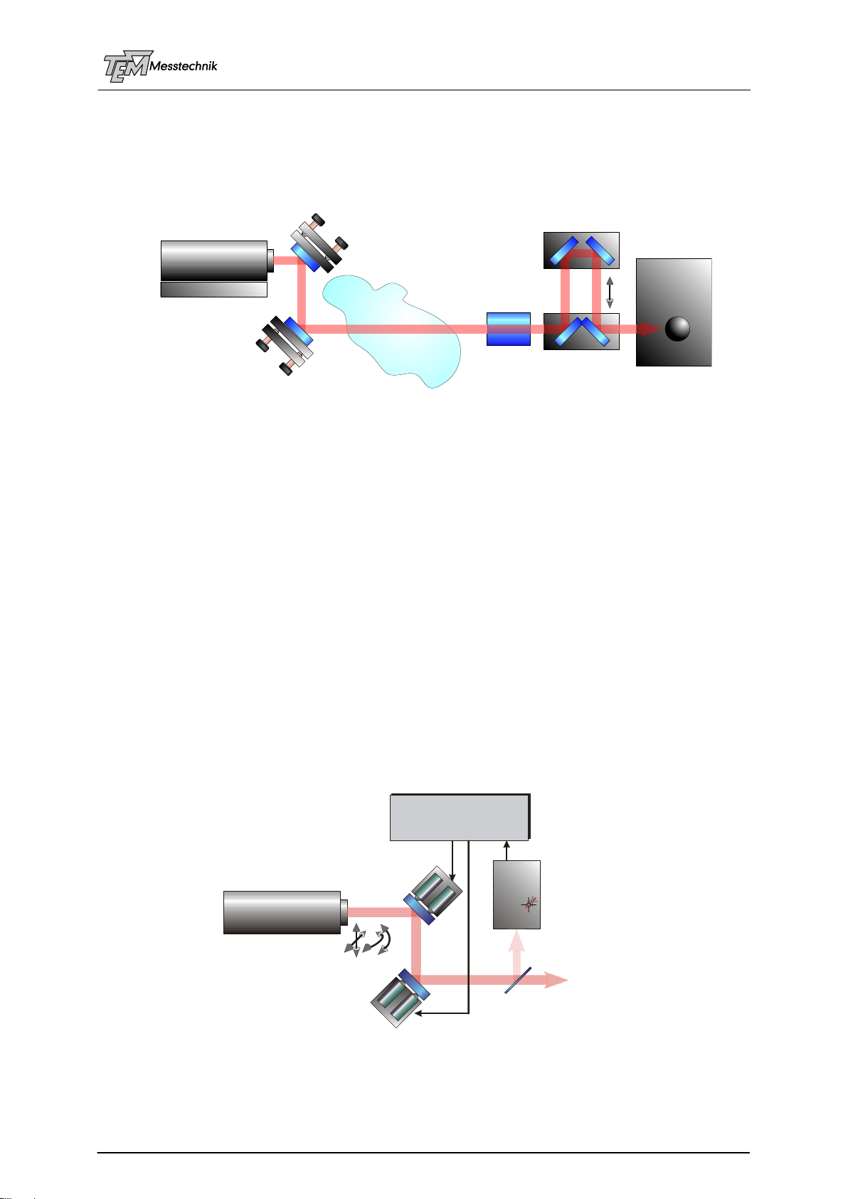
The laser beam pointing stabilization system Aligna®compensates for all of these disturb-
ances. The laser beam position and its angle are measured by the 4D position sensitive detec-
tor PSD 4D in four degrees of freedom (two beam positions “X” and “Y”, and two angles “”
and “”). The position of a (collimated) laser beam is characterized by these four values, like a
line in space. The measured deviation signals of the laser axis with respect to the reference
axis are processed continuously by the Aligna®electronics. Herein control signals for four
piezo actuators of the BeamScan mirrors and/or motorized mirror mounts (Aligna60, e.g.) are
generated. Two 2D movable mirrors, which control these four degrees of freedom in four fast
closed lock loops keep the laser beam exactly at the reference axis.
Aligna®is a modular system, consisting of different elements, which can be adapted to the
individual application: Different types of scanners (with various values of displacement, beam
diameters, mirror types, movement speeds) and different types of PSDs (Position Sensitive
Laser
Cooling System
1: thermal drifts
inside the laser,
movements by
frequency detuning,
by power variation
2: thermal drifts
of cooling system
and mechanical mounts
3: drifts of alignment
and folding mirror
holders 4: air fluctuations and
temperature gradients
6: moved optical elements
(delay lines, switching mirrors,
motorized telescopes,...)
7: Movement of the experimental
(optical) tables or vacuum chambers
5: thermal effects in
optical elements and
mirrors
Target
Laser
BeamScan 2D
1PSD 4D
BeamLock®
electronics
BeamScan 2D
2
XY
Beam Splitter
to Experiment

Aligna® 4D User Manual
8 / 84
Detectors) with various types of sensors (wavelength, beam diameter, resolution, dimensions,
QUAD detectors, duo/tetra lateral PSDs, or CCD/CMOS cameras) are available.
In some applications a 2D stabilization (instead of 4D) may be suitable. In this case only one
2D scanner BamScan 2D is necessary. (This reduction, however, can be more critical and
takes more effort in positioning the PSD. Please refer to chapter “2D or 4D stabilization”!)
Aligna®4D electronics 4D detector PSD 4D e
BeamScan2D with different mirror shapes, 1-inch and square bodies
Elliptical mirror 22 x 32 mm, (5mm thick), fitting into std 1-inch mirror holder
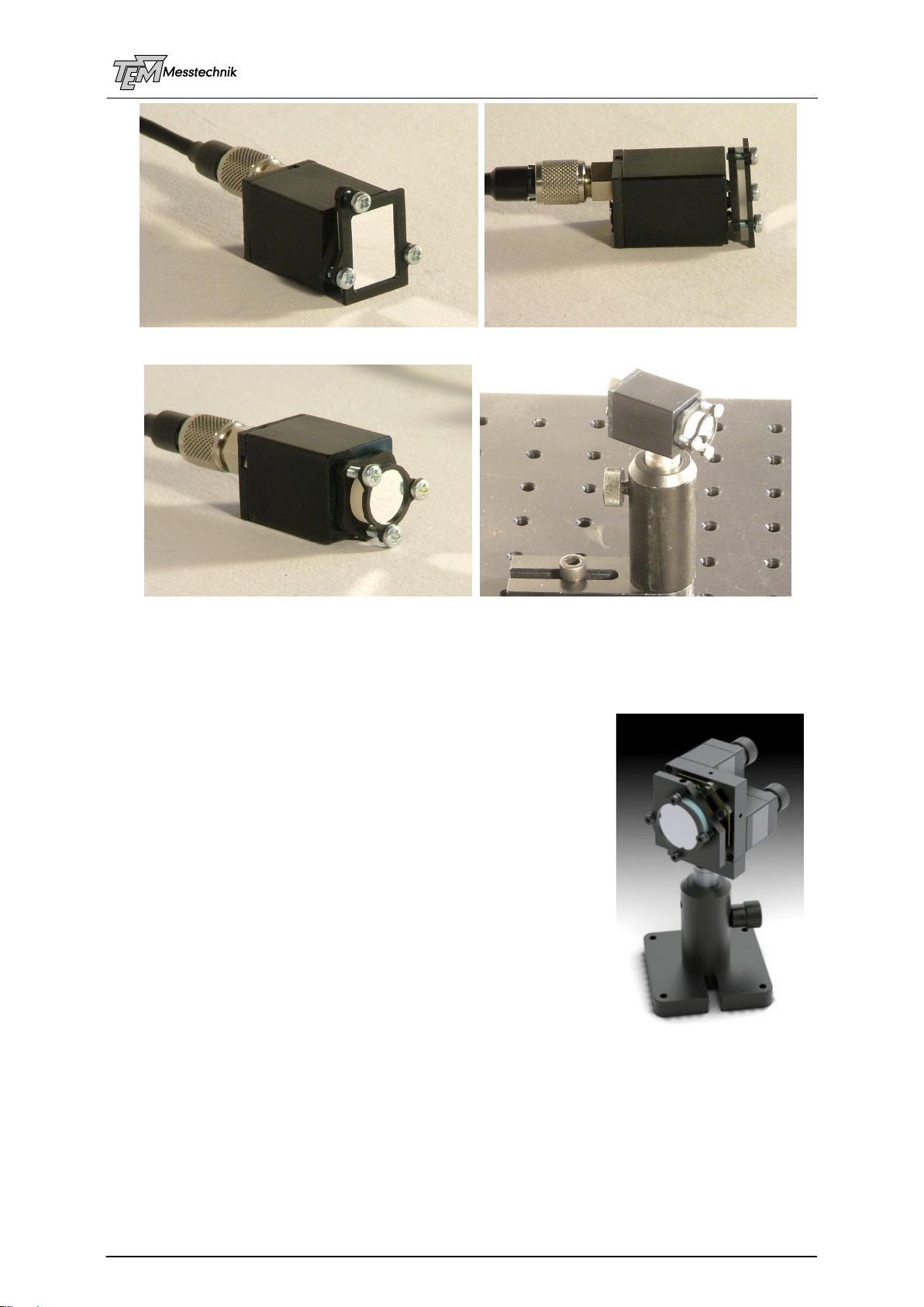
Aligna® 4D User Manual
9 / 84
rectangular broadband mirror 15 x 20 x 2.5 mm, in rectangular corpus
Half-inch mirror, rectangular corpus
Aligna®also can be controlled by a PC or by other electronic
devices within a control system. In this case both the 2D beam
position and the 2D beam direction can be set by the control
system; a very precise stabilized 2D or 4D fast scanning of the
laser beam is possible.
Via the USB or serial interface, the following parameters can be
set and controlled:
Switching each servo channel on or off
control of the set points (position X, Y, and angle , )
Gain of the PSD amplifiers (sensor sensitivity)
…
For detailed information please consult the Software Manual.
In addition all relevant signals (4D position signals, 4D error signals, 4D regulation signals,…)
can be read as analog signals or via USB interface.

Aligna® 4D User Manual
10 / 84
2 Block Diagram Aligna®4D
In the following, the block diagram of the Aligna®4D electronics is described.
Note: This chapter is preliminary: It still contains additional information related to former ver-
sions.
Two 2D sensors “PSD 2D” (or one 4D sensor “PSD 4D”) detect both 2D position (“X”, “Y”)
and 2D angle (“”, “”) of a laser beam. The detector electronics contain (dependent on the
detector type):
The position sensitive chip: A variety of detector sizes and types is available: 2x2 mm,
4x4 mm, 9x9 mm, 12x12 mm, others on request, as well as quadrant detectors of different
sizes. Different speed options are available, please refer to PSD manual.
The detectors are located at a small PCB, which also contains transimpedance amplifiers
and filter networks to achieve very linear low noise robust signals.
The detectors are connected with the cables “PSD 1” to “PSD 4” with the Aligna®4D electron-
ics, which contains following functions.
signal range and clip check for each channel Ax, Ay, Bx, By
Input Cross-link Matrix circuitry (ICL Matrix) (calculation of pure Angle and BeamPosition
signals)
Set point definition (SetpAx, SetpAy, SetpBx, SetBy), fixed, external analog control or digital
control (including test generator)
Error calculation (4D actual position –4D set position)
Gain and regulator control logic
Four PIDT2regulators
Output Cross-link Matrix circuitry (OCL Matrix) (calculation of the combination movement)
Monitor multiplexer for observation of all relevant signals
HV Piezo amplifiers
Motor Drivers
MicroController Module, including USB Interface, Serial Interface, (Ethernet optionally)
Power Supply
Aligna® 4D User Manual
11 / 84
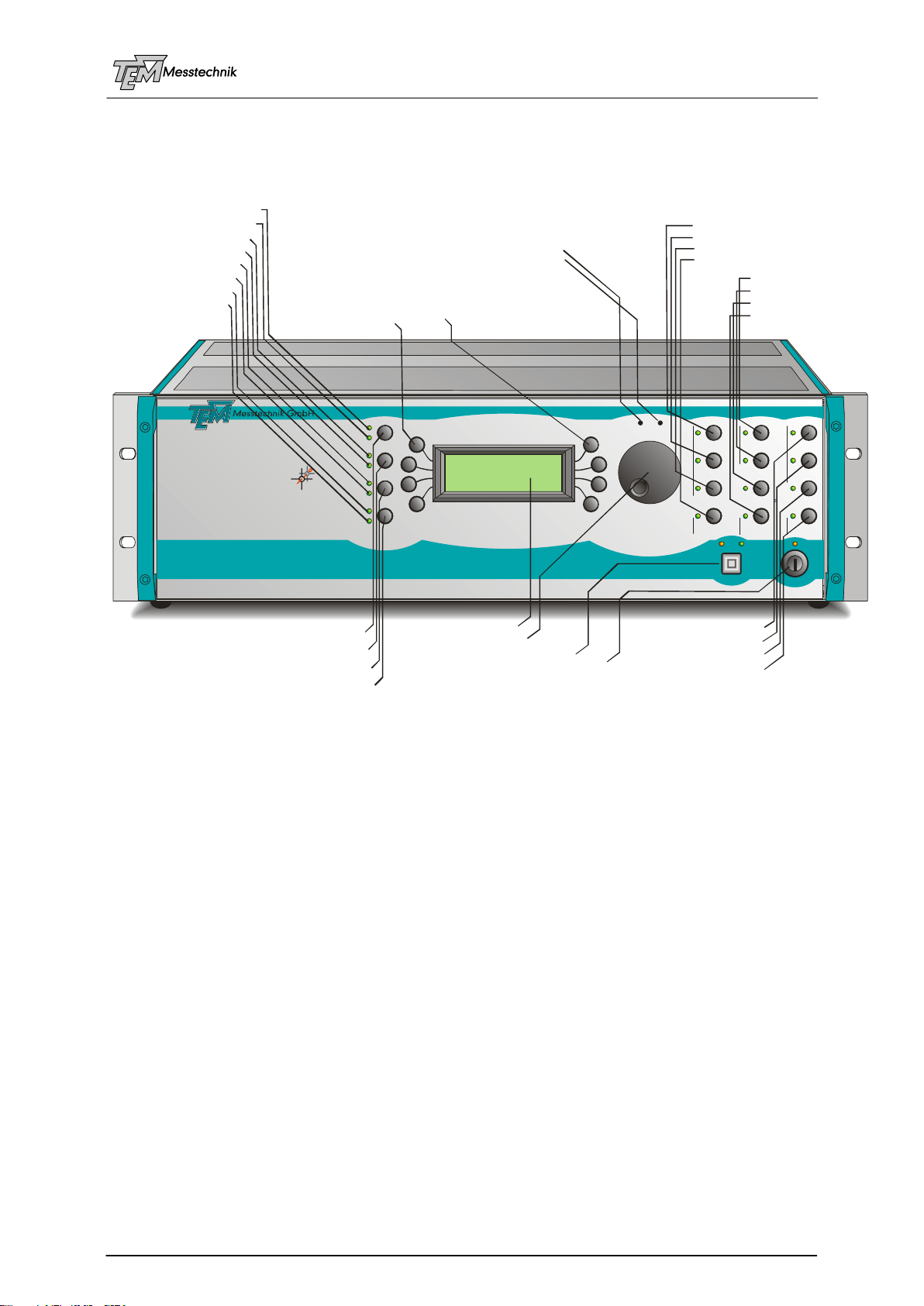
3 Short Description of the Front Panel Elements
Station
Parameters
Task
volume
brightness
station 3
manual
station 2
station 1
here is 0!
aux
auto detect
piezo enableoptimize!
center!
search!
intensity A
position OK
piezo active
A active
intensity B
locked
aux
B active regulate!
4DBeamLock System
Aligna two-point-O
Modular Laser Beam
Alignment andStabilizationSystem
USB
TR
power
®
®
www.TEM-Messtechnik.de
Aligna 4D 3.1
TEM Messtechnik GmbH
SN 2033 (Demo DPG10)
Release 16.02.2010
start procedure "search"
12 programmable user key buttons
LED "intensity OK" detectorA
(spec. key#0)
(spec. key#1)
reset/set error bit
activate servos A, B, A+ B
LED "intensity OK" detectorB
LED "position OK" all detectors
LED "locked" all servos
LED "piezo servo(s) active"
LED "aux" (errorbit, e.g.)
LED servo(s) Aare active
LED servo(s) Bare ac tive 8 menu keys
LCD menu display
trim LCD illumination brightness
trim loudspeaker volume (beep, key click,...)
start procedure "center"
start procedure "optimize"
switch on/off regulation (servos)
select manual access
auxillary userkey
enable piezo servo(s)
"here iszero"key
select station/tool # 1
select station/tool # 2
select station/tool # 3
automatic station detection
front panel USBinterface
selection wheel
front panel supply key switch
Pinnings of connectors are described in appendix “Connectors and Cables”.

Aligna® 4D User Manual
12 / 84
4 Principles of Laser Pointing Stabilization
4.1 Reasons of Pointing Instabilities
Laser beams, used in an experiment or in industrial applications, can move in space by many
reasons. Even small movements at the laser outlet may result in rather large movements of
the laser spot, depending on the distance to the target, and on the optical components in the
beam path. In the following, some of the most important reasons of pointing instabilities will be
named.
Reasons of Pointing Instabilities
4.1.1 Thermal properties of the laser itself
Often a high local power is dissipated in a small spatial region; even small thermal movements
can be transformed by collimating lenses of short focal lengths to relatively large angle move-
ments. Local heating may be caused by pump diodes, by gas discharges, flash lamps, or by
electrical excitation of the laser medium itself.
4.1.2 Thermal movement by the laser cooling system
If the laser medium is producing heat the laser is often cooled by Thermo-Electric Coolers
(TEC, Peltier elements), by fans or by a water cooling system. Those techniques produce
temperature gradients within the mechanical setup. If the development of the device is not
done in a perfectly temperature compensated manner, position and angle changes will result.
Even if the laser medium itself is stabilized and held at an exact constant temperature the
cooling system has to react on changing temperatures of the environment and it has to com-
pensate for the temperature change of the heat sinks. This will lead to pointing drifts.
4.1.3 Drifts of alignment and folding mirrors
Adjustment tools and element holders typically consist of different materials: Aluminum, stain-
less steel, brass and other materials, with different thermal expansion coefficients each.
Caused by a change of the environment temperature the different thermal expansions can
lead to position and –more critical- angle movements of the laser beam. The strength of these
effects strongly depends on the construction, the materials, and –of course- on the tempera-
ture variations of the environment.
4.1.4 Air turbulences and temperature gradients in the air
Air fluctuations may cause large pointing fluctuations, particularly at long distances. But even
one meter distance can produce pointing fluctuations in the order of some ten microns, which
may be too much for critical applications. Air fluctuations often play the main role in beam
pointing instabilities, especially at long distances between laser and target of several meters or
even several tens or even hundreds of meters. Using evacuated tubes for beam guiding over
Laser
Cooling System
1: thermal drifts
inside the laser,
movements by
frequency detuning,
by power variation
2: thermal drifts
of cooling system
and mechanical mounts
3: drifts of alignment
and folding mirror
holders 4: air fluctuations and
temperature gradients
6: moved optical elements
(delay lines, switching mirrors,
motorized telescopes,...)
7: Movement of the experimental
(optical) tables or vacuum chambers
5: thermal effects in
optical elements and
mirrors
Target

Aligna® 4D User Manual
13 / 84
long distances helps, of course, but even small effects at the path from the laser outlet to the
vacuum tube will be transformed to large effects at the end of the (long) tube. Please note,
using evacuated tubes may cause drifts depending on local air pressure variations.
In addition, evacuated tubes are expensive, bulky and inconvenient to handle.
If a laser is lead between different rooms through holes in the wall temperature and pressure
differences between these rooms may lead to strong local air density gradients and thus to
strong pointing drifts. Local pressure differences between the rooms (by air conditioning sys-
tems or by laminar flow systems, e.g.) will cause a strong air flow and air density turbulences.
4.1.5 Thermal effects of optical elements
Every optical element absorbs a distinct amount of the laser beam, which is true for both re-
flecting and transmitting elements. So-called thermal lenses lead to well-known influences of
the collimation properties of the laser beam. With high quality of the materials and coatings
and/or at low intensities the focusing/defocusing effect may be negligible.
But: the (very small) absorbed power leads to a local change of the temperature itself and thus
the temperature gradient, which leads to a pointing deviation. The related time constants can
be very slow, no equilibrium may be reached in many hours.
4.1.6 Mechanically moved optical elements (delay lines, e.g.)
Sometimes optical elements have to be moved within the application:
4.1.6.1 Delay Lines
In short pulse laser systems (ps or fs durations) so-called delay lines are often used to match
or shift two laser pulses in time with respect to each others. A set of several mirrors is moved
by a motorized sleigh which has to be aligned to be exactly parallel to the optical path. This
can only be done to a certain extent; it is difficult to align better than some ten micro radiants.
In addition, the motorized rail is not perfectly straight; there will be curvatures in the order of
typically some ten up to some 100 microns, depending on the length and the price of the rail.
4.1.6.2 Motorized or Manual Telescopes or Zoom Expanders
In some applications, setups of optical lenses have to be moved (telescopes, zoom telescopes,
expanders,…). It is impossible to position and move these elements exactly at the optical axis.
Thus, a beam pointing movement will be observed during the movement of the optical element.
4.1.6.3 Switching Mirrors
In some applications, the laser beam is switched between two paths of the experiment by a
manually operated or by a motorized switching mirror. The reproducibility of the mirror position
may be very high, but will not be perfect. Residual uncertainties of approx. ten µradiant are
typical.
4.1.7 Movement of the experimental (optical) tables or vacuum chambers
Often the laser and the experimental target are mounted at different optical tables. Many ex-
periments are located in small or large vacuum chambers. Those components will be at differ-
ent and changing temperature values. This leads to relative pointing drifts, even if each ele-
ment is very stable by itself.
Aligna® 4D User Manual
14 / 84
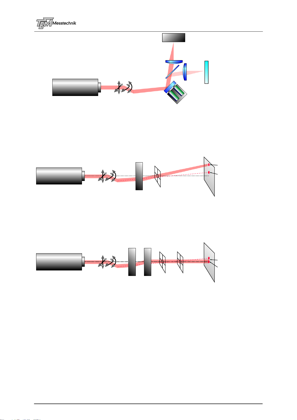
4.2 2D or 4D Stabilization?
The movement of a collimated beam can be separated into four dimensions: two translational
("X", "Y") and two rotational ("", "")
These degrees of freedom are not really independent: If, for example, one mirror holder drifts
by 100 µrad due to the change of the room temperature the translation error of some µm will
be negligible compared to the beam diameter of let's say some mm close to the mirror. After
one meter free propagation, however, this leads to a movement of 0.1 mm, after 10 meters
this is 1 mm, which is really not negligible any more. (Note: the angle drift is not directly de-
pendent on the propagation length in this example. In reality, however, angle fluctuations due
to air fluctuations increase with the length with a factor of sqrt(L))
Even if the nature of the drift (in this example) is a pure angle drift (just 2D) it leads to a com-
bination of angle and position movement after a distance of propagation (near the experiment)
and cannot be compensated for by one single 2D moving mirror. It has to be compensated for
with a combination of position and angle correction, e.g. by two 2D moved mirrors.
In many applications it is not really necessary to keep the laser beam fixed both in position
AND direction at the place of the experimental target. In the case of laser material processing,
for example, it is very important to keep the focused laser spot at an exactly defined position at
the target surface. The angle, however, is not that critical. So one could think, a 2D correction
might be sufficient. A beam splitter (also called beam sampler) separates a small part of the
main beam. This part is handled exactly as the main beam (distances, focusing elements, etc.).
If the laser spot is actively held fixed by the actuator at the detector position, it will be fixed in
the plane of the target, too.
XY
Laser
drifting mirror angle
compensation by a combination
of position and angle reference direction
and position
Aligna® 4D User Manual
15 / 84
In principle this works. But: The detector has to be positioned in an exact (!) image of the
target. Therefore it has to be aligned mechanically very well. Often it is difficult to find the
correct Z-position for the detector. If this Z-position of the detector is wrong the stabilization
can even ENLARGE the pointing fluctuations, compared to the situation WITHOUT any stabili-
zation!
This shows: the fixed point of a laser beam has to be well matched with the target require-
ments. In normal cases this needs additional optics in the detection path, corresponding to the
main optics and distances in the main path, and it needs a precise and critical alignment of the
detector and the related optics.
With a 4D stabilization, in contrast, two points of the beam are fixed in space, instead of one
point in case of 2D. As a result, ALL points of the output beam are fixed. For this it is not im-
portant WHICH two points are fixed. They only have to have a certain distance from each
other to get enough resolution for the angle measurement. The Z-positions of the detectors are
not critical. They can be positioned within a coarse spatial range and need not to be aligned
precisely.
If PSDs are used (not quadrant detectors, see description on "detectors", “PSDs or QUAD
detectors”) it is not important to hit exactly the center of the detectors: PSDs create a linear
signal proportional to the spot position within the detector area, independent of the spot size
and of the spot shape. (In contrast, quad detectors can only be used exactly in the physical
center of the detectors; they show a strong dependence of the position error signal from the
spot size and shape.) Thus PSDs do not have to be aligned precisely in X and Y position,
because the servo loop (the user, respectively) can select the working point by applying an
electronical DC set point signal (X and Y, and ) to the regulator electronics. (Thus even the
stabilized beam can be scanned quickly and precisely.)
XY
Laser
Target
Beam Splitter
Pointing Drifr and Fluctuations
2D Position Detector
in the position
of an image of the target
XY
Laser
2D steering element
(tilting mirror, e.g.)
ONE fixed point
of the beam
without stabilization
with stabilization
XY
Laser
two 2D steering element
(tilting mirrors, e.g.)
two fixed points
of the beam
without stabilization
with 4D stabilization

Aligna® 4D User Manual
16 / 84
As a result, the PSD 4D detector box has to be aligned just coarsely. It can be fixed firmly
without the need of precision alignment mechanics. The exact reference optical axis can be
controlled by electronic signals, instead of fine mechanical alignment!
Of course a 4D lock system needs a little bit higher effort in the electronic system, compared
to a 2D system (two 2D detectors, two actuator mirrors), but:
A 4D stabilization leads to a much more robust and easy to handle system, without the
necessity of mechanical fine alignment and very low mechanical drift!
It compensates for both angle AND position shifting effects.
Both position AND angle will be corrected without optimizing for one of them, without de-
tailed analysis of the movements and drifts.
No fine adjustment of the detectors is necessary.
Aligna®4D gives you both possibilities: It can be switched to 2D or to 4D stabilization. Even in
the 2D mode you have the advantage of watching both, position and direction, by help of the
4D detector.
In addition, a 2D stabilization can be performed by a combination movement of all four actua-
tors.
Moreover, the servo speeds may be selected different for angle and position stabilization,
which leads to higher precision, as described later.
Aligna® 4D User Manual
17 / 84
4.3 Positioning of Actuator and Detectors
In the following, we will discuss different setups to get the best setup of positions of the piezo-
controlled mirrors, the motorized mirror mounts, and the 4D detector system.
It is obvious that the detection of the beam movement has to be located BEHIND the actuators.
Otherwise a movement of the actuators cannot be observed by the detectors for pointing
correction in a closed servo loop.
In addition, it is obvious that the detectors should be located near the target (or experiment).
Then, all disturbances appearing at the path from the laser, passing maybe many folding
mirrors and optical elements, will be detected and compensated for.
It is NOT the case that both actuators should be located in the near of the experiment. The two
actuators may be located anywhere in the path up to the detectors. Of course, different posi-
tions have advantages and disadvantages, which will be discussed now:
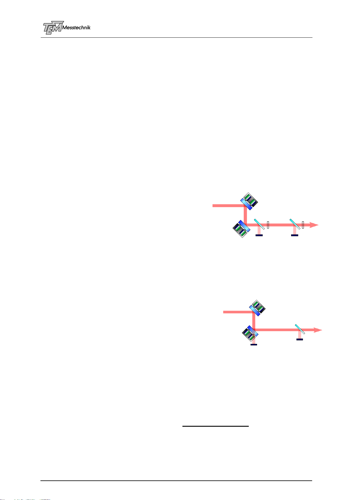
4.3.1 Setup 1: Two Beam Samplers
We will start with the perhaps most easy to understand setup:
Two mirrors are mounted at piezo-controlled mirror holders. Four piezos can control four de-
grees of freedom: Two translational (X, Y), two rotational
(, ).
Two 2D detectors represent two points of the laser beam.
The electronics keeps the beam exactly in the center of
both detectors. That means that two points of the beam
are fixed. Thus the complete beam will be fixed (as far
as no disturbance will happen BEHIND the detectors).
The position resolution is directly given by the position sensitivity of D1. A large distance be-
tween D1 and D2 leads to a high angle resolution. (The angle deviation is the difference of
both position deviations.) On the other hand, both detectors should be placed near by the
experiment. Therefore, a good compromise has to be found.
4.3.2 Setup 2: Second Mirror Acts as Beam Sampler
In the practical use it might be somewhat inconvenient to
use two beam samplers. We can use the second actuator
mirror as a beam sampler, because even very highly reflect-
ing mirrors will transmit a small amount of light. We only
need power in the order of some microwatts.
In this setup, detector D1 only observes the movement of
actuator A1. In fact, a movement of A2 will also cause a very
little beam movement at D1 due to beam shifting. However, this effect is negligible under
nearly all conditions. Detector D2, in contrast, observes a movement of A1 AND A2.
4.3.3 Problems with Beam Sampler Plates
A beam sampling glass plate (or a beam splitter cube), located in the main beam path, may
influence the beam quality, if the flatness, the transmission properties or the polishing is
non-perfect. High quality elements have to be used.
In most applications, beam sampler glass plates with parallel surfaces or beam splitter cubes
are NOT APPRECIATED:
D1 D2
A1
A2
D1
D1’ D1’
D2
A1
A2

Aligna® 4D User Manual
18 / 84
A glass plate may cause interference effects due to multiple reflections between surfaces.
Because of this effect, glass plates with a small angle (wedge plates) are preferred.
However, they cause a (very small) angle deviation from the original direction.
In femtosecond laser applications the glass in the beam path may cause unwanted disper-
sion effects.
However, the problem of interference will not appear with fs laser applications: A pulse of
50 fs, e.g., has an optical length of approx 15 microns. The optical path length difference
between both reflections of a 1 mm glass plate is 100 times longer! Therefore, both reflect-
ed pulses would not interfere. here it is not necessary to use plates with an angle.
In this case thin plates (1...2 mm) are preferred. In most applications, the dispersion effects
can then be neglected.
It is very important to mount the glass plates without mechanical stress to avoid birefrin-
gence and deforming of the surfaces. Note: The reflected beam will define the reference ax-
is for the pointing stabilization. Any movement of this reference beam will directly lead to
movements of the main beam! Thus, a very thin glass thickness of less than 1 mm is not
recommended.
An uncovered glass plate at 45° splits approx. 1% of the beam for one polarization direction
(p-light) and 12 % for the other polarization direction (s-light). Both values differ by more
than an order of magnitude, which leads to strong unwanted polarization dependence of the
test beam intensity.
In most applications both values (1% and 12%) lead to test beam intensities which are far
above the necessary intensities of some microwatt. These test beam intensities have to be
reduced by strong optical filters, and they are lost for the main beam.
With horizontally polarized laser light, it is possible to get very low reflection rates by using
a reflection angle of around Brewster’s angle, approx. 57°. This angle will be slightly more
difficult to align compared to a 45° angle.
One (or both) surfaces can be AR (anti-reflex coated) for the target wavelength at 45°
deflection. However, it is not easy (and thus not cheap) to get high quality broadband AR
coatings with well-defined reflection grades, while HR mirrors are more easy to get.
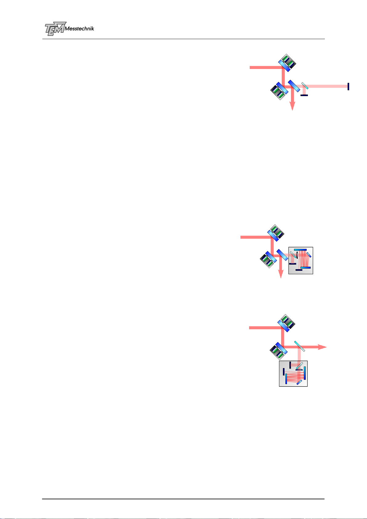
4.3.4 Setup 3: High Reflecting Mirror Acts as Beam Sampler
Because of these problems, it is usu-
ally better to use the transmission of a
HR (high reflecting) mirror as a beam
sampler. The transmissions are typi-
cally of the order of 1% down to
0.01%, which is by far enough in most
cases.
However, the polarization dependence of the transmitted beam can be
large. Especially high-bred mirrors for high-power or high energy fs pulse
lasers may have a polarization difference between s and p light by factor
of 100 or even 1000.
(Often HR mirrors for the target wavelength, in contrast to AR coated
substrates, are easier to get from stock.)
The distance between D1 and D2 defines the angle resolution.
In many applications, there are a lot of folding mirrors in the beam path.
One of the last mirrors before the experiment can be used as detection beam sampler for D2.
D1
D2
A1
A2
Aligna® 4D User Manual
19 / 84
4.3.5 Setup 4: Only One Beam Sampler Mirror
In a similar setup, a (nearly) non-polarizing 50% beam splitter
(plate or cube) is introduced behind a non-moved high reflecting
mirror, used for coupling out the test beam. This avoids the diffi-
culty of using the mirror at A2 both as mirror AND as beam sam-
pler. It leads to a smaller and more robust construction of A2. In
addition, it gives the advantage that the ratio of the intensities of
D1 and D2 only depends on the (known) properties of the detector
beam splitter, not on different transmissions of two HR mirrors.
Most of the problems with a beam sampler plate described before are not important here,
because the beam splitter is not located within the main beam path (dispersion, highest sur-
face quality and flatness, HQ AR coatings,...). Interference between surfaces has to be con-
sidered, as well.
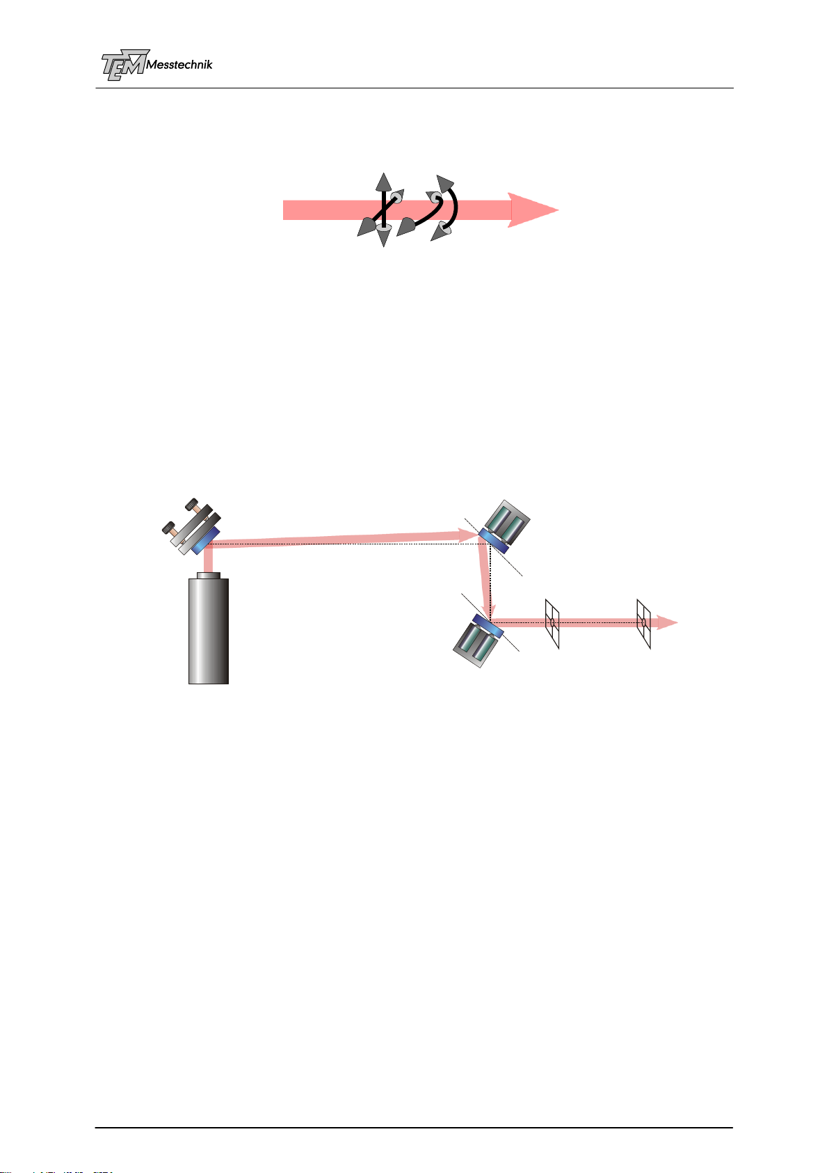
4.3.6 Setup 5: Compact 4D Sensor "PSD 4D"
The distance between D1 and D2 determines the angle resolution. The introduction of optical
elements can shrink down the necessary size of the detection setup:
1. A lens can create a far field image at the detector D2: If D2 is located in the focal plane of
a lens; the detector is imaged to infinity. This detector will not register a (parallel) transla-
tion of the beam at all, as the lens laws show. It only registers angle movements. Therefore,
this would be a pure angle detector, while detector D1 acts as a pure position detector.
However, at a given detector size the angle resolution will
increase with increasing the focal length. The optimum
resolution is reached, if the focused spot diameter has
nearly the detector size.
2. For getting a compact design the beam can be folded by
mirrors back and forth, which leads to a very compact 4D
detector, as realized in the "PSD 4D" detector box, which
has the dimensions of only 80 x 80 x 40 mm.
The sketched setup here is the mostly used one with Aligna®applications
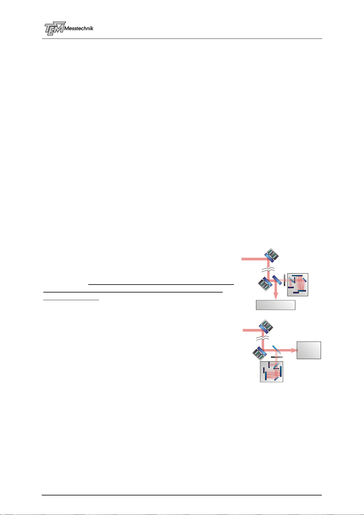
4.3.7 Setup 6: "PSD 4D" with Beam Sampler
Wedge Plate
Of course it is also possible to use a glass beam sampler for the
creation of the test beam to be lead into PSD 4D. The setup
shown here is often used for testing purposes, because in many
cases no change of a pre-existing optical setup is necessary. It
has to be clarified that the beam sampler plate does not cause
problems (too high losses, dependence on polarization, disper-
sion, interference).
Excessively high intensities at the detector have to be handled
by optical filters.
D1
D2
A1
A2
D1 D2
PSD 4D
A1
A2
A1
A2
D1
D2
PSD 4D
Aligna® 4D User Manual
20 / 84
What is the Best Setup? Some Selection Rules
All of the described setups can be realized with the Aligna®4D (using PSD 2D or PSD 4D,
different types of beam samplers). The user may decide which fits best to his application.
However, there are some rules for selection:
4.3.8 Distance between A1 and A2
The distance between A1 and A2 defines the possible compensation of the beam translation
movement, while the possible rotation movement is independent on this distance.
Of course, in most cases a small and compact design is appreciated. What are the criteria?
If there is a large distance between the laser and the experiment, even small angle move-
ments are translated into large transversal movements. In these cases, a large distance be-
tween the mirrors A1 and A2 is recommended. If the distance from the laser to the experiment
is many meters, the optical path distance A1 to A2 should be 50 cm or more.
The standard actuators BeamScan 2D can move the mirror by an angle range of 2.3 mrad in
X and Y direction. That means with a distance between A1 and A2 of 1 meter a beam dis-
placement of up to over ± 2 mm can be compensated. This is quite sufficient for most applica-
tions.
One mm or more will only be necessary with very long laser beam distances of over 5…10
meters, depending on environmental properties, or with the use of delay lines and other mov-
ing optics. In fact, it is not easy and takes some time to align a delay line to much better than
some 100 microns of beam shift (depending on the moved rail length of course).
4.3.9 Position of the Detector(s)
The 4D detection should be located close to the experiment,
because only disturbances in the path BEFORE the detector can
be detected, and thus can be eliminated.
Even if a large variety of positions and distances can be handled
by Aligna®4D the best position of the 4D detector (or the first of
the two PSD 2Ds) is as close as possible behind the second
actuator mirror A2. (Of course, the necessary beam sam-
plers/mirrors and maybe filters for adjusting the detection beam
power have to be between A2 and the detector.)
In this case, the four servo loops can mostly be separated from
each other. This leads to a more stable and robust locking be-
havior.
D1 D2
PSD 4D
Experiment
Experi-
ment
A1
A1
A2
A2
Filter
Filter
D1
D2 PSD 4D
Table of contents
Other TEM Industrial Equipment manuals


