TEM FiberLock User manual

FiberLock Manual
TEM Messtechnik GmbH
July 26, 2021
FiberLock
FiberLock
www.TEM-Messtechnik.de
output
input
lock
power
status
program
reset
intensity
9V - 18V
USB
TEM Messtechnik GmbH
Grosser Hillen 38
D-30559 Hannover
Tel: +49 (0)511 51 08 96 -31
Fax: +49 (0)511 51 08 96 -38
E-mail: mailto:info@TEM-messtechnik.de
URL: http://www.TEM-Messtechnik.de


FiberLock Manual
Contents
1 Delivery Content 4
2 Basic Operation 5
2.1 Principles........................................ 5
2.2 Recommended Hardware Setup . . . . . . . . . . . . . . . . . . . . . . . . . . . . 6
2.3 Scanning........................................ 6
2.4 Locking......................................... 8
2.4.1 Optimization of all Parameters . . . . . . . . . . . . . . . . . . . . . . . . 9
2.5 SearchFunction .................................... 9
2.6 SavingSettings..................................... 9
2.7 OperationWithoutPC................................. 9
3 Advanced Operation 11
3.1 IntensityThresholds .................................. 11
3.2 ModulationAmplitude................................. 11
3.3 Noise-EaterMode ................................... 11
3.4 ChoppedLasers .................................... 11
3.5 ScaledOutputSignals................................. 12
3.6 List of Variables and Commands . . . . . . . . . . . . . . . . . . . . . . . . . . . . 12
3.6.1 Communication Syntax . . . . . . . . . . . . . . . . . . . . . . . . . . . . 12
3.6.2 VariableTable ................................. 13
3.6.3 CommandTable................................ 14
4 Software Installation 15
4.1 Installation of the Kangoo Software . . . . . . . . . . . . . . . . . . . . . . . . . . 15
4.2 Installation of LabView Drivers . . . . . . . . . . . . . . . . . . . . . . . . . . . . 16
4.3 InstallingtheUSBDrivers............................... 16
4.4 UpgradingtheFirmware................................ 17
5 Connectors and Electrical Specifications 18
5.1 MainsPowerCable................................... 18
5.2 BNCConnector .................................... 18
5.3 HD-15Connector ................................... 18
6 Safety Instructions 19
7 Customer Service 20
FiberLock Manual
July 26, 2021 3 / 21

FiberLock Manual
1 Delivery Content
Your FiberLock system consists of the following components:
•FiberLock electronics: contains a pre-amplifier for the photo diode input, a microcontroller
for digital signal processing and communication with a PC and output amplifiers to drive the
piezo-based actuator
•Piezo-actuator mirror: the standard actuator is a piezo-driven mirror which tilts in x- and
y-directions
•Power adapter
•HD-15 extension cable
•Software installation CD
Please check the contents of your delivery for completeness.
FiberLock Manual
July 26, 2021 4 / 21

FiberLock Manual
2 Basic Operation
Single mode fiber coupling is often time consuming, because very high mechanical precision in the
sub-micrometer range is necessary. Expensive translating and tilting devices with good long-term
stability must be used. In order to optimize the amount of light coupled into the fiber, various
components of the setup may be moved alternatively:
•the laser beam by redirecting mirrors on piezo actors
•the coupling optics (e.g. a small aspherical lens)
•the fiber end itself (e.g. for open fibers without attached fiber connectors)
The FiberLock simplifies this process in two ways: Firstly, it can scan the laser in x- and y-directions.
This makes finding the fiber aperture much easier and the live display capabilities allow the convenient
optimization of other degrees of freedom, such as the focus. Secondly, as the name suggests, the
FiberLock can lock the laser beam onto the fiber aperture and efficiently compensate for drifts and
vibrations in the optical setup, eliminating the need for manual re-adjustment.
2.1 Principles
The FiberLock connects to an optical assembly via two connectors. The input connector (BNC
plug) is connected to a photo diode signal, which detects the intensity of light coupled into the
optical fiber. The output connector (HD-15 socket) controls the position of the piezo-mirror. This
should be placed just in front of the collimating lens. This way, tilting the piezo-mirror leads to
position changes of the beam focus.
FiberLock
piezo scanner
single-mode fiber
laser
optional PC
photo detector
output
input
lock
power
status
program
reset
intensity
FiberLock
FiberLock
www.TEM-Messtechnik.de
12V
FiberLock Manual
July 26, 2021 5 / 21
FiberLock Manual
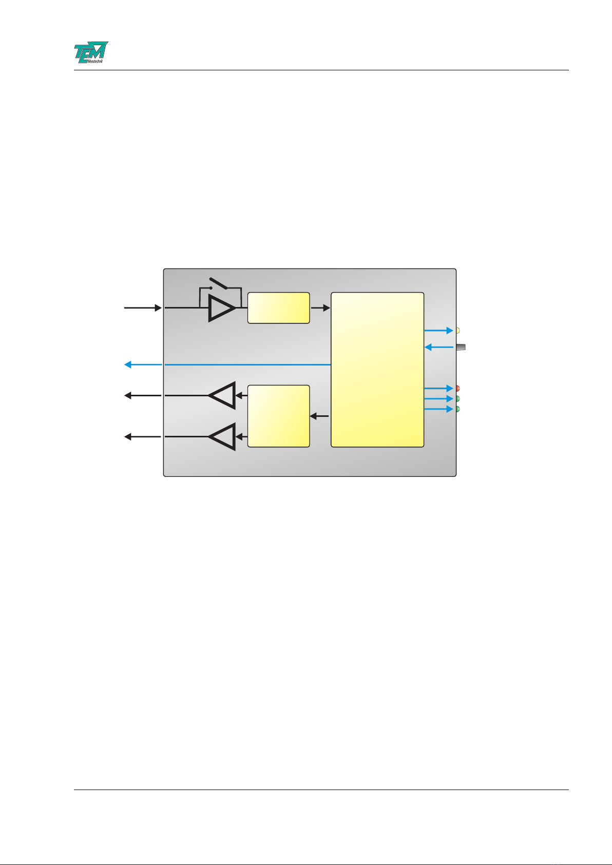
Optionally, the FiberLock can be connected to a PC via USB. On the one hand, this facilitates
to parameterize and customize the electronics. On the other hand, the scanning functionality can
visualize the fiber coupling and help to optimize other degrees of freedom, such as the beam angle
or the focus. Internally, the FiberLock features an input amplifier with electronically adjustable
wide-range gain. The gain-adjusted analog input signal passes an analog-to-digital converter before
entering the micro-controller core, which takes care of all signal processing. In locking mode, this
controller adjusts the x- and y- angles of the actuator mirror with two lock-in regulators, generating
the necessary modulation signals. In scanning mode, the measured photo diode signal is processed
and sent to the PC for visualization. Any output to the actuator is converted to analog voltages
with digital-to-analog converters and subsequently amplified by fast op-amps to the working range
of the piezo actuator.
input amplifier
ADC
gain switch
AVR32 core
DACs
Ÿsine generator
Ÿ2 channel lock-in-
regulator
Ÿscan generator
Ÿgeneration of
visualization data
output amplifiers
BNC
plug
HD-15
plug
USB
0-10V
+/-30V
+/-30V
status
lock / search
intensity
2.2 Recommended Hardware Setup
To get the full benefit from working with the FiberLock, a few guidelines concerning the hardware
setup should be followed. Firstly, the piezo actuator should be attached to an adjustable mirror
mount to allow for manual compensations of the mirror angle if the actuator working range is
exceeded. Please place the actuator as close to the collimating lens a possible Secondly, another
adjustable mirror should be present in the beam path in order to change the beam position on the
collimating lens. Lastly, the focussing lens and an optional mode-matching lens should be easily
movable along the optical axis, so that their positions can be optimized “live”, while the FiberLock
is active. These hints are shown schematically in Fig. 1.
2.3 Scanning
To facilitate and visualize the initial coupling into the fiber, it is possible to scan the fiber aperture
using the full range of the piezo actuator. During this raster scan, the laser intensities at the fiber
output are recorded and can be viewed as a 3-D plot. To this end, it is necessary to connect a PC
to the FiberLock electronics and start the Kangoo software. In fact, the scanning functionality is
only available in combination with a connected PC.
FiberLock Manual
July 26, 2021 6 / 21

FiberLock Manual
position adjustment angle adjustment
piezo scanner
focus adjustment
Figure 1: Recommended hardware setup for a FiberLock system.
Figure 2: Software interface for scans.
Figure 2 shows the software interface for the scanning functionality. The scan is started or stopped
using the blue and red “START” and “STOP” buttons at the bottom of the frame. The drop-down
list to the right of these buttons changes the view angle of the 3D plot. In addition, the scan
FiberLock Manual
July 26, 2021 7 / 21

FiberLock Manual
frequency and scan range can be changed. To the right of the frame, the gain of the input amplifier
can be adjusted. The LED-button “Gain switch” turn the input amplifier into a transimpedance
amplifier for the case that a photo diode is directly connected to the FiberLock electronics.
Once a peak has been found during scanning, the 3D display can further be used to optimize this
peak and move it to the center of the actuator’s working range.
2.4 Locking
In the Kangoo software, please change to the locking view using the “LOCK” button at the top
of the interface. This shows a 2D-display of the current actuator position, an intensity indicator
and a recorder to track intensity changes (c. f. Fig. 3). Start the lock by pressing the “Lock”-LED
in the software interface or by pressing the FiberLock’s front panel key. This will start the lock-in
regulator, which adds a small circular modulation to the actuator position. If the actuator is not
aligned to achieve optimal fiber coupling, this modulation will show in the output intensity. This
allows the lock-in regulator to correct the actuator position and stabilize it to maximize the fiber
coupling efficiency.
To achieve good results, please adjust the input gain such that the intensity is at about fifty
Figure 3: Software interface for locking with intensity recorder.
percent. Using the “PosGain” dial, the gain of the position regulator can be adjusted. A very low
gain value will make it difficult for the regulator to follow during manual adjustments to the system,
while excessively large gain values lead to oscillations which will show in the measured intensities.
FiberLock Manual
July 26, 2021 8 / 21

FiberLock Manual
2.4.1 Optimization of all Parameters
Fiber coupling depends on a number of alignment parameters, for example the angle at which the
laser enters the fiber, the position of the fiber aperture and the focus position along the axis of
the fiber. In a typical optical setup, these parameters are not independent of each other: Changing
the focus can hardly be done without affecting the position of the fiber aperture, a change of
the horizontal beam angle typically also affects the vertical angle, etc. This makes the manual
optimization of all involved degrees of freedom very difficult and time-consuming.
Although the FiberLock only locks two degrees of freedom (say the horizontal and vertical beam
position), this greatly simplifies the manual optimization of the remaining parameters. The focus
position, for example, can now be changed without worrying about affecting the beam position,
since this will be automatically adjusted by the FiberLock. If the gain of the position regulator is
well adjusted, all other degrees of freedom of the fiber coupling can be manually adjusted in a fast
and simple manner without ever losing the lock.
2.5 Search Function
The search function can be triggered from within the software or by pressing and holding the button
on the front panel. The FiberLock will start to scan over the fiber aperture and automatically lock
on to the found intensity peak. This functionality is very useful when the coupling has been lost,
for example by manual misalignment of the optical elements. As long as the misalignment is small
(within the scan range of the actuator), the search function will re-lock within seconds.
2.6 Saving Settings
Any parameter changes are lost as soon as the FiberLock loses power or resets. In order to make
changes permanent, the dialed settings must be committed to the microcontroller’s non-volatile
memory. This is achieved with the “VarSave” button in the Kangoo interface. To change saved
settings, simply overwrite them by changing some parameters and pressing “VarSave” again. At the
next system start, these saved settings will be loaded and used as default parameter. An exception
to this is the started of the regulator, which is always off at start-up.
2.7 Operation Without PC
While it is useful to connect the FiberLock to a PC for visualization and for setting parameters, the
device can work on its own and is indeed intended to do so for every-day operation. The following
description of the front and real panel elements shows how to operate the FiberLock without a PC.
21 3 4 5 6
BNC
7 810 9
FiberLock Manual
July 26, 2021 9 / 21

FiberLock Manual
1 Program button. Used for firmware upgrades only.
2 Reset button. Resets the FiberLock electronics; equivalent to disconnecting and recon-
necting the power supply.
3 Intensity indicators. These show the currently measured photo diode intensity, with
software-adjustable thresholds.
4 Push button. Press short to start/stop the locking. Press and hold to start a search.
5 Status LED. Slow breathing: idle; fast breathing: locking; very fast breathing: searching;
continuously on: scanning.
6 Power LED. Lights up as soon as the device is powered.
7 Power connector. Takes DC input voltages, 9 to 18V. 2.5mm pin. GND on ring.
8 BNC connector. For connecting a photo diode signal. Input range: 0...10V.
9 USB connection.
10 HD-15 connector. Provides the driving signals for the piezo actuator.
A typical situation is the following: The FiberLock is switched on, but the optical setup has drifted
and the optimal actuator position has changed. This will be indicated by the three front-panel LEDs,
which act as a simple but efficient intensity indicator. If at least some intensity still couples into the
fiber, press the key to activate the locking function, and the FiberLock should immediately lock to
maximum intensity. If the fiber coupling has drifted too far and no light is coupled into the fiber,
press and hold the key until the search function starts. The FiberLock will search for the position
of the fiber and then automatically switch into lock.
FiberLock Manual
July 26, 2021 10 / 21

FiberLock Manual
3 Advanced Operation
3.1 Intensity Thresholds
In order to show whether the lock is intact or whether the fiber-coupling drifts when locking is off,
the FiberLock has a simple intensity indicator in the form of three LEDs in the front panel. If the
intensity is too high, the red LED lights up. If the intensity is too low, only the left green LED will
light up. The corresponding intensity thresholds can be changed in the software interface.
CAUTION: The lower intensity bound has a second function: During a search scan, the search will
terminate as soon as an intensity value above this lower threshold is detected. Therefore, setting
the threshold too low or excessively high may interfere with the search functionality.
3.2 Modulation Amplitude
When locking, the mirror angles are modulated by the lock-in regulator. For a one-dimensional
system, this would lead to intensity fluctuations in the fiber output light. The FiberLock, however,
locks in two dimensions, which opens a way to circumvent this problem. The sinusoidal modulations
of the x-Axis and the y-Axis are phase shifted by 90 degrees, leading to an effective circular motion
of the beam focus on the fiber aperture. For a well-focused, round laser beam, this means that the
intensity coupled into the fiber is constant (the focus is moving on a constant level curve of the
intensity distribution). By changing the size of the modulation circle, we can effectively control the
amount of light coupled into the fiber. For most applications, this intensity should be maximized,
corresponding to a small circle size. A larger circle size on the other hand will lead to a more robust
lock and may make sense in noisy setups.
3.3 Noise-Eater Mode
The FiberLock can, in addition to locking to the maximum coupling intensity, work in “Noise-Eater
Mode”. In this mode, the quality of the fiber coupling is constantly adjusted in order to achieve a
constant intensity at the fiber output. This “Noise-Eater Mode” is enabled by the “Intensity Reg.”
button. The actuator now modulates much more slowly and constantly adjusts the modulation
radius in a attempt to keep the output intensity at a constant level. As a side-effect, this will deform
the orbit shape whenever the laser’s beam profile is not circular. For elliptical beam profiles for
instance, this mode can be used to force an elliptical modulation orbit of the actuator. Using the
blue “Save” button, this orbit can be saved and then switched on or off using the “Smart Orbit”
LED button. Once learnt, the smart orbit functionality also works when the regulator is not in
“Noise-Eater Mode” and can greatly reduce the residual intensity fluctuations introduced by the
actuator’s modulation.
3.4 Chopped Lasers
The FiberLock works for with chopped lasers up to a chopping frequency of about 1kHz. The elec-
tronics automatically detect whether the intensity input signal is chopped and reacts accordingly.
Therefore, no additional parameterization is necessary. The only adjustable parameter is “Chop-
perOffThreshold”, found in the section “Hidden Parameters”. Here, one can enter the threshold
FiberLock Manual
July 26, 2021 11 / 21

FiberLock Manual
(in percent of the maximum intensity) below which the laser is considered off, or blocked by the
chopper.
Even the Noise-Eater mode works with chopped lasers, but the regulator gain may have to be
optimized to achieve a good performance.
3.5 Scaled Output Signals
Please note that the two output signals of the FiberLock are not equally scaled. The output in x-
direction is reduced by a factor of √2to compensate for the fact that mirror tilts in the x-direction
deflect the laser stronger than tilts in the y-direction. This is important for the orientation of the
piezo-actuator: It’s x-axis should be aligned to the plane spanned by the incident and the refected
beam (typically the plane of the optical table). By the variable FL Scale this scaling can be switched
on/off.
3.6 List of Variables and Commands
3.6.1 Communication Syntax
The communication between PC and microcontroller is carried by an ASCII-encoded stream of char-
acters. (Exceptions are sometimes made in order to achieve fast binary data transfer.) The stream
is structured in lines, the ends of which are marked by ASCII 13 (carriage return), followed by ASCII
10 (line feed).
Lines can be sent to the microcontroller (and in turn received from the µ)C by:
•entering them literally in the COM window of Kangoo or another terminal such as Microsoft
HyperTerminal
•application programs such as Kangoo or LabView “Virtual Instruments”
•user-written programs, using languages like VB (Microsoft Visual Basic), C/C++, Delphi, etc.
with help of COM procedures.
Both the microcontroller and the PC may send lines at any time. Please note that the microcon-
troller sometimes sends information without ”being asked for”. This means that the line received
by the PC right after a query does not necessarily contain the answer to the query. Therefore a
communication routine has to be programmed to catch all incoming lines and to parse them for the
information of interest: Every single line has to be interpreted by the respective receiver.
An ASCII 39 (apostroph) character denotes a comment: the apostroph and all subsequent charac-
ters are deleted before the evaluation of the line.
The microcontroller distinguishes between ”commands” and ”variable assignments”.
If the line does not contain an equal sign, the microcontroller interpretes it as a ”command line”.
Tokens within the command line have to be separated by ASCII 32 (space) characters. The first
token is taken for the command name, all further tokens are parameters to the command.
FiberLock Manual
July 26, 2021 12 / 21

FiberLock Manual
Example: If the microcontroller receives
helphCRi
it will send a list of available commands to the PC.
Example: If the microcontroller receives
help hellohCRi
it will send information about the command ”hello”, if available. In this case the token ”hello” is a
parameter that is handed over to the command ”help”.
If the line contains an equal sign (not preceeded by a space!), followed by a value, it is interpreted
as a variable assignment.
Example: If the microcontroller receives
CutOff= 1000hCRi
it will set the value of ”CutOff” to 1000 and echo the value:
CutOff= 1000hCRi
An ASCII 92 (backslash) at the beginning of the line suppresses the echo.
Example: If the microcontroller receives
\CutOff= 1000hCRi
it will set the value of ”CutOff” to 1000 and not echo the value, unless the value was not accepted.
(In that case the echo will tell the actual value.)
If the rest of the line (after the equal sign) does not contain a value, the microcontroller responds
telling the actual value. (This is a query for a value.)
Example: If the microcontroller receives
CutOff=hCRi
it will send back
CutOff= 1000hCRi
A complete list of variables and their values can be obtained by sending the command ”vardump”:
If the microcontroller receives
vardumphCRi
it will echo one line for each available variable, in the style
hvariablenamei=hvalueihCRi
3.6.2 Variable Table
The following table lists FiberLock variables. At the terminal, these can be listed by entering the
command “VarDump”.
Variable Default Min Max Comment
FiberLock Manual
July 26, 2021 13 / 21

FiberLock Manual
SerialNumber - - - serial number of the device
Build 283 0 99999 encodes the firmware version
FL PosX, -Y 0 -2048 2047 x- and y- positions of the piezo actuator
FL MinRadius 50 1 4095 minimum modulation radius
FL TransImp 0 0 1 transimpedance switch for the input amplifier
FL PosGain 100 0 65536 gain for the position regulator
FL RadGain 3000 0 65536 intensity regulator gain in NoiseEater mode
FL RadPosGain 20 0 65535 position regulator gain in NoiseEater mode
FL PdGain 500 0 1000 gain of the input amplifier
FL IntReg 0 0 1 enables the NoiseEater mode
FL Volts 0 2000 - raw signal from ADC in mV
FL Scale 1 0 1 Scaling of the x-Piezo by factor 1.41
ScamM Mode 0 0 1 0: off, 1: scan, 2: search, 3: lock
ScanM StepsX 41 2 50 number of rows and columns for a scan
ScanM FreqX 250 1 10000 scan frequency, arbitrary units
ScanM Range 1000 1 2047 scan range
FL IntLow 400 1 2000 lower intensity threshold
FL IntHigh 1600 100 2047 upper intensity threshold
FL IntSet 1000 100 2047 set point for the NoiseEater mode
FcutOff 10000 200 200000 cut-off frequency of the input low-pass filter [Hz]
FL Orbit 0 0 1 enables the smart orbit
FL AutoRelock 0 0 1 enables the automatic re-lock search
FL RelockPeriod 3000 10 60000 time before re-lock search [ms]
FL RelockThreshold 50 0 100 re-lock threshold (in % of min. intensity)
FL ChopThreshold 5 -10 100 laser-off threshold for chopped lasers
FL IsrFreq 12800 0 21300 loop speed of the regulator
3.6.3 Command Table
The following table lists FiberLock commands. At the terminal, these can be listed by entering the
command “CmdDump”.
Command Arg. 1 Arg. 1 Comment
Reset - - resets the micro-controller
Stop - - stops scans, searches or locking
FL PrntVars - - prints the current intensity and actuator positions
SaveOrbit - - saves the current orbit as smart orbit
FL VarSave - - saves settings to EEPROM (equivalent to “VarSave”)
FiberLock Manual
July 26, 2021 14 / 21
FiberLock Manual
4 Software Installation
4.1 Installation of the Kangoo Software
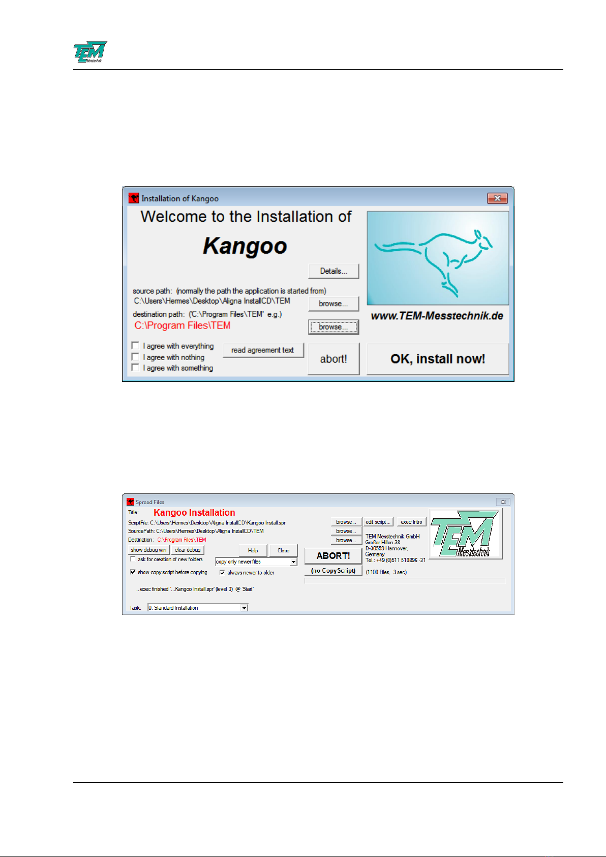
To install the Kangoo software, start the program Install.exe in the root directory of the installation
CD or USB memory stick, resp.. The installer will show a welcome screen with several options.
The default options should work fine, with the possible exception of the section “Destination Path”,
where the destination directory is specified. The standard directory is “TEM” in the “Program
Files” folder. On Windows Visa or Windows 7 systems, please avoid the “Program Files” folder and
choose and a different path, for example “C:/TEM”. The button “OK, install now!” starts copying
all required files from the source path to the destination path. During the installation procedure,
the installation program checks all required files.
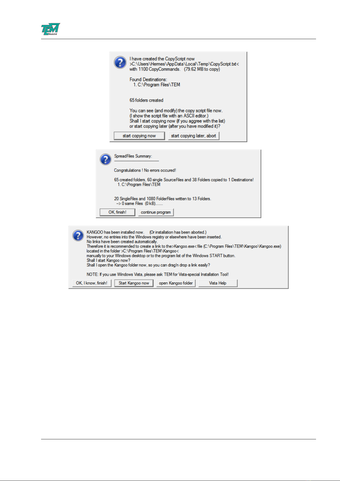
The program then creates a list of file copy commands. When this list is complete, you can check
the list and start the copy procedure.
FiberLock Manual
July 26, 2021 15 / 21
FiberLock Manual
4.2 Installation of LabView Drivers
To install LabView demo VIs and their Sub-VIs, simply copy the content of the folder /TEM/LabView
of the installation CD or USB memory stick, resp.., to your local LabView folder.
Please note that the NI-VISA package is required, which can be downloaded from the National
Instruments web site.
4.3 Installing the USB Drivers
Typically, when the USB connection between the micro-controller and a PC is first made, Windows
will open the Found New Hardware Wizard. Here, choose to install drivers from a user-specified
location. The necessary driver file is located in the directory “TEM/Service/USB Driver” in the
Kangoo installation directory (or on the install CD or memory stick). The Hardware Wizard will
now finish the installation and no further configuration will be necessary.
Once the installation is complete, Windows will assign a COM-port. To find out which COM-port
has been assigned, check for a new entry in the section “Ports (COM & LPT)” of the device
FiberLock Manual
July 26, 2021 16 / 21

FiberLock Manual
manager. The device will appear as “TEM uC Virtual Com Port” in the device manager of your
computer (see figure 4).
Figure 4: TEM COM Port in the device manager
4.4 Upgrading the Firmware
Please contact TEM Messtechnik for details about firmware upgrades.
FiberLock Manual
July 26, 2021 17 / 21
FiberLock Manual
5 Connectors and Electrical Specifications
5.1 Mains Power Cable
Please use the included power supply. When using a different power adapter, ensure that it provides
a direct voltage in the range 9V to 18V and at least 1.5A of current.
5.2 BNC Connector
The BNC connector is the input for the photo intensity signal at the fiber output. It can serve
as both current and voltage input, with a software switch to select either mode. If an external
pre-amplifier is used, use an input signal between zero and ten volts.
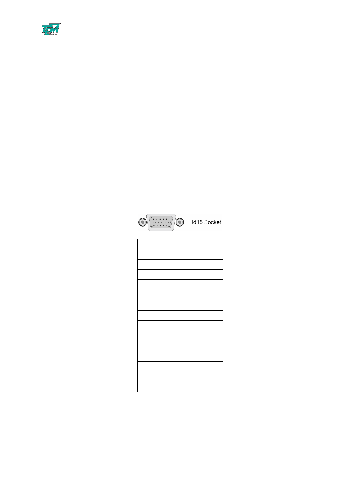
5.3 HD-15 Connector
NOTICE: Only use the cable delivered with your system. Using standard cables like those that are
used for personal computers can lead to malfunction or damage of electronic components. Many
available cables have internal connections (common shielding of R, G, B) or some pins are not
connected.
1
2
3
4
5
6 +15V
7 -15V
8 GND
9
10 -HV (-30V or -60V)
11 Output A
12 Output B
13
14
15 +HV (+30V or +60V)
FiberLock Manual
July 26, 2021 18 / 21

FiberLock Manual
6 Safety Instructions
Before operating the FiberLock, please read this user guide carefully in order to avoid any damage
of the device or connected equipment as well as any injury to persons.
CAUTION! The FiberLock device is intended for laboratory use only. The FiberLock device should
be operated by trained personnel.
CAUTION! The FiberLock device is used with lasers emitting visible or invisible radiation. Do not
stare into the laser beam! Take precautions to avoid exposure of direct or reflected laser radiation.
CAUTION! The user is responsible for keeping the legal rules concerning laser safety that apply in
their country. In Germany, this is the “Unfallverhtungsvorschrift BGV B2” of the “Berufsgenossen-
schaft der Feinmechanik und Elektrotechnik”.
CAUTION! Use only the supplied power adapter and plugs or the corresponding ones for your coun-
try, as only this guarantees safe operation and grounding of the device.
CAUTION! The FiberLock is intended for indoor operation with a temperature range of +5◦Cto
+45◦C. Do not subject to heat, direct sunlight or the influence of other electric devices. Protect
from humidity, dust, aggressive liquids and vapors.
CAUTION! The FiberLock should be opened by trained technical personnel only. Before opening
the housing, the device must be disconnected from the supply voltage, for example by pulling the
power plug.
Please keep this manual within easy reach to refer to if needed. Give your FiberLock to third parties
only with this manual.
FiberLock Manual
July 26, 2021 19 / 21

FiberLock Manual
7 Customer Service
In case of service needs, general questions, need of repair or warranty claims you will get quick and
effective support at:
TEM Messtechnik GmbH
Grosser Hillen 38
D-30559 Hannover
Germany
Tel: +49 (0)511 51 08 96 -30
Fax: +49 (0)511 51 08 96 -38
E-mail: mailto:info@TEM-messtechnik.de
URL: http://www.TEM-Messtechnik.de
FiberLock Manual
July 26, 2021 20 / 21
Table of contents
Other TEM Industrial Equipment manuals


Popular Industrial Equipment manuals by other brands


Charmhigh
Charmhigh CHM-T48VB manual

RINGSPANN
RINGSPANN HW 075 FHM Installation and operating instructions

KTR-Group
KTR-Group KTR-STOP XS F B Series Operating & assembly instructions

Fein
Fein Grit GXE Series Translation of the original instructions

Reflex
Reflex Variomat VG Instructions for use

WOOD'S POWR-GRIP
WOOD'S POWR-GRIP MR1611LDCO instructions