OPA 161RKTY (c/w EC motor & UC7 Controller)
Packaged Reverse Cycle R410A
Air Cooled Air Conditioner Installation &
Maintenance
shown returns the fan control voltage
down to the minimum value for 'High'
fan speed (3.0V).
v. When the desired setting for high
fan speed is selected then wait for
30 seconds. The controller will save
the selected value in its memory and
return to normal operation.
vi. To adjust the indoor fan 'Low' speed
repeat the above procedure but wait
until the display shows the letter 'L'
before releasing the push button. The
factory default value for low speed is
5.5V.
If the air returning to the indoor unit is
regularly expected to be above 50%RH,
then the coil face velocity should be limited
to be 2.5 m/s or less (refer Air Handling
graph in Technical Data pamphlet).
High humidity levels can occur in tropical or
subtropical conditions, and/or when heavily
moisture laden fresh air is introduced. Select
a fan speed that avoids water carry-over
problems.
CHECK TESTS
1. Leave the remote switch in the off
position and close the mains isolating
switch.
A four hour delay period is required to
allow the crankcase heater to drive any
liquid refrigerant out of the compressor
oil.
2. Check that all fan motors are free
running.
3. Check that the thermostat is correctly
wired to the unit and is set at the desired
temperature.
4. Checkthattheairlters,ifany,have
been correctly installed.
5. Check any supply air diffuser dampers
are open.
START UP PROCEDURE
Use the supplied Commissioning Sheet to
help you complete the following procedure:
1. Switch on the unit after the four hour
delay period for the crankcase heater
has expired.
2. Check for correct rotation of the
compressor. If rotation is incorrect the
compressor will not pump, be noisy, and
will draw minimal current. To correct
motor rotation, change the phasing at
the main power terminal.
3. Check the supply voltage.
4. Measure the current draw on the
compressor motor and on each fan
motor. Check all readings against the
speciedvalues-particularlytheindoor
fan amps if the unit is installed in a free
blow application.
Compressor
The compressor is directional scroll
type. The compressor lubricant is polyol
ester oil (POE). Note, this oil absorbs
moisture quickly if exposed to open air. On
commissioning, the compressor must be
checked for correct rotation (refer Start Up
Procedure).
ELECTRICAL REQUIREMENTS
Electricalworkmustbedonebyaqualied
electrician. The outdoor unit must be wired
directly from a distribution board by means
of a circuit breaker and a mains isolator
provided - preferably close to the unit.
Standard units are suitable for use with
thermostats with either manual Heat/Cool
selection or automatic changeover subject
to the contact ratings of the thermostats.
To connect alternative thermostats (non-
communicating contact switching types),
refergure2forwiringdiagram.
A 24 hour power supply to the crankcase
heaters is required, otherwise the warranty
is void.
INDOOR FAN SPEED
The Indoor fan can be switched ON through
the thermostat by selecting High, Medium
or Low fan speed, or via BMS. This can be
done without starting the compressor.
1. Check the operation of the indoor fan for
noise and vibration.
2. CheckiftheHighspeedairowisto
specication.
3. CheckiftheLowspeedissufciently
low yet without risk of frost on the indoor
coil.
4. Refer wiring diagram for the factory
default setting of the maximum fan
speed and the fan speed range High –
Low.
5. If either High speed or Low speed need
adjusting, use the UC7 Controller board
to adjust the indoor fan speed:-
i. Ensure the compressor is off and the
thermostat or BMS does not request
for the compressor to start.
ii. Press and hold down the SW3 push
button on the UC7 circuit board until
the display shows the letter 'H', then
release the push button.
iii. The indoor fan will start and run at the
'High' speed setting (factory default
setting is 7.5V). The display will show
the value ('7.5') and the indoor fan will
run at the selected speed.
iv. Each following press on the SW3
push button increases the indoor fan
control voltage in steps of 0.5V, up
to a maximum of 10.0V. Pressing the
push button again when value 10.0 is
GENERAL
This OPA 161 unit must be installed in
accordance with all national and local safety
codes.
OPTION (Field Fitted)
TZT-100 Room Temperature Controller
INSTALLATION
Positioning
Refer to dimension diagram for minimum
clearances. If multiple units are to be placed
side-by-side then allow at least 2 m between
coil faces.
Mounting
Fastentheunitdowntoarmathorizontal
base using the four holes provided in the
mounting rails.
When the unit is being installed on a roof
it is recommended that the unit is installed
on a substantial structure with with anti-
vibration mounts or pads beneath the unit.
Flexible duct connections are recommended
between the supply and return ducts and
the unit.
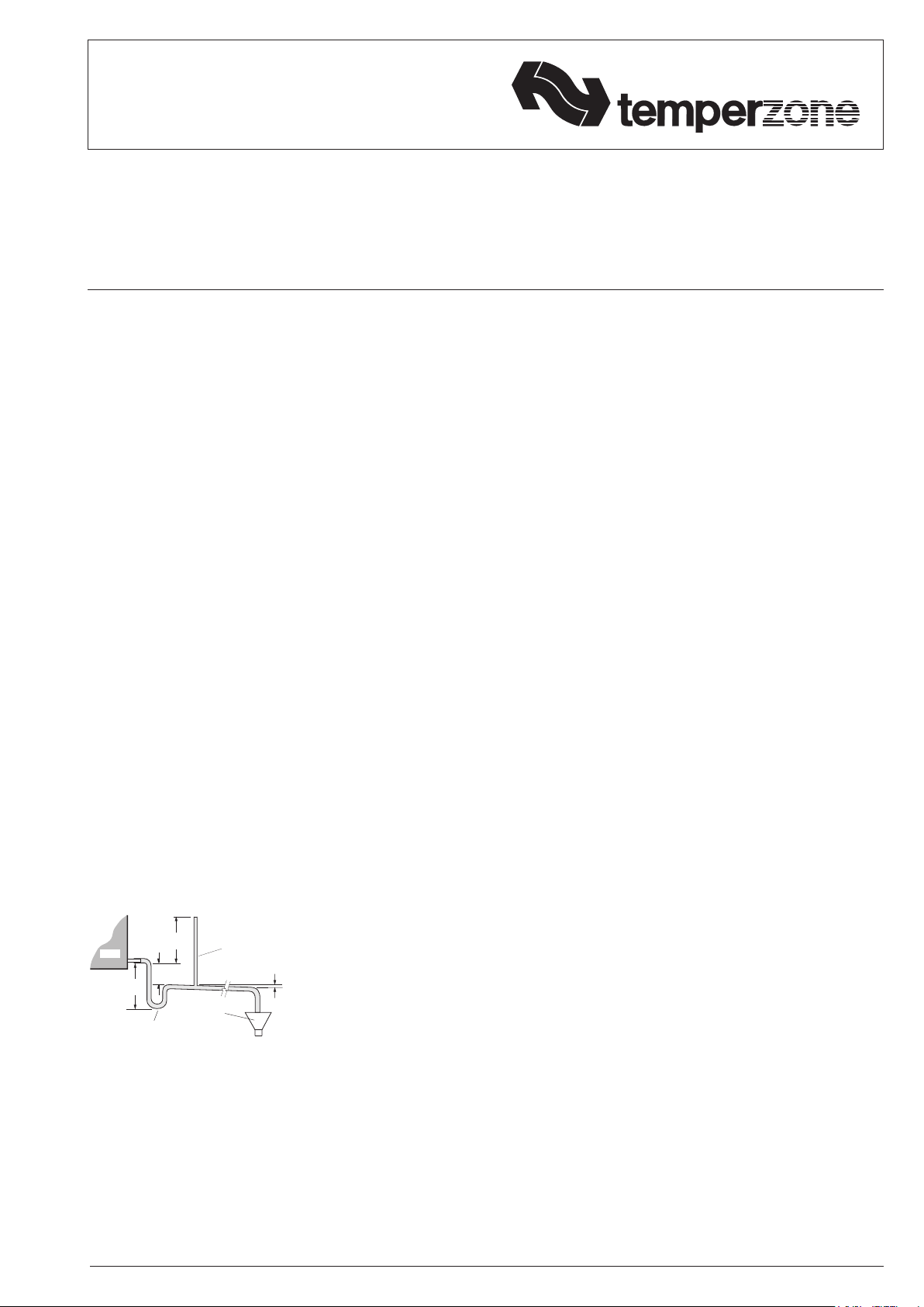
Condensate Drain
The condensate drain should be 'U' trapped
outside the unit. The trap should have a
vertical height of at least 50 mm. The drain
should have a slope of at least 1 in 50 and
must not be piped to a level above the unit
drain pipe.
Forlongcondensatepiperuns,tavent
pipe near the drain trap. The top of the vent
pipe must be at least 100 mm above the
OPA unit's drain tray.
REFRIGERATION SYSTEM
General
The refrigeration system has been charged
with R410A refrigerant; refer wiring
specicationtableforamount.Tapping
points are provided to measure discharge
and suction operating pressures. Beware of
high system pressures; use correct guages.
OPEN
DRAIN
MINIMUM
SLOPE
20 mm PER m
(1 IN 50)
50 mm
MINIMUM
100 mm
APPROX.
'U' TRAP
100 mm
APPROX.
VENT PIPE
FOR LONG
CONDENSATE
DRAIN RUNS
UNIT


