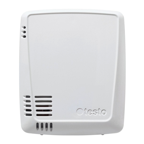
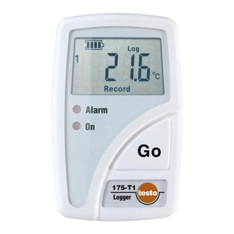
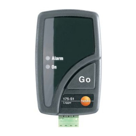
TESTO 0572 2200 Series User manual

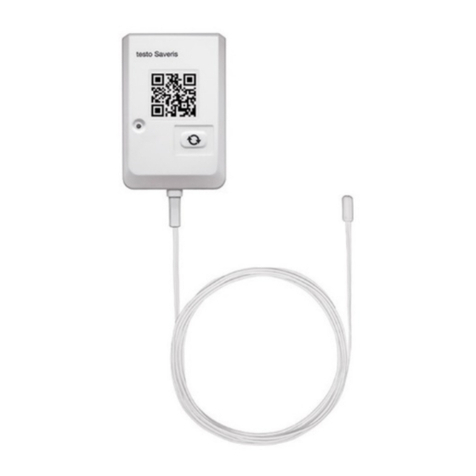
testo Saveris radio data logger
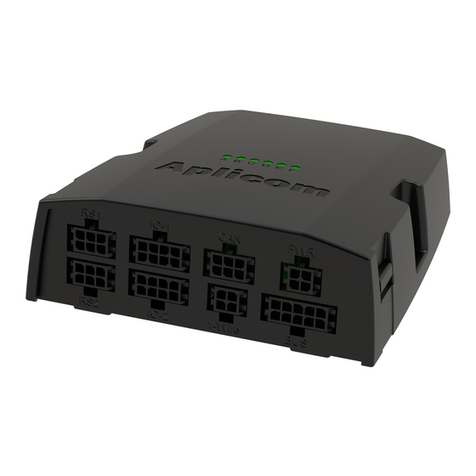
0572 2200 XX Gateway
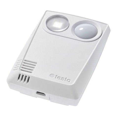
0572 2201 XX radio data logger –ambient temperature
0572 2202 XX radio data logger –temperature product simulation
0572 2203 XX radio data logger –door contact
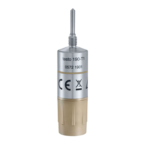
0572 2204 CC radio data logger –core temperature
Instruction manual for NSF testing
V2

Table of contents
Table of contents
1About this document ...................................................................................2
1.1 Usage.....................................................................................................2
1.2 Symbols .................................................................................................2
2Safety and disposal .....................................................................................3
Take the testo information document into account (accompanies the
product)...............................................................................................3
2.1 Warning..................................................................................................3
3System description......................................................................................3
3.1 System Overview ...................................................................................5
3.2 Product description.................................................................................5
3.3 radio data logger –ambient temperature ...............................................7
3.4 radio data logger –temperature product simulation...............................7
3.5 radio data logger –door contact.............................................................7
3.6 radio data logger –core temperature.....................................................7
3.7 Gateway button functions & LED............................................................8
3.8 Radio data logger button functions & LED .............................................9
4Commissioning..........................................................................................10
4.1 Mounting on the wall ............................................................................10
4.2 Mounting of communication module to the Gateway............................10
4.2.1 WLAN module and PoE module............................................11
4.2.2 Power supply / batteries ........................................................12
4.3 Configuration of the Gateway...............................................................12
4.3.1 Account / Saveris Connect Key .............................................12
4.3.2 NSF-certification account.......................................................12
4.3.3 Gateway offline configuration ................................................13
4.4 Connecting a radio data logger ............................................................15
5Software......................................................................................................16
5.1 Saveris Restaurant Software................................................................16
5.1.1 Access...................................................................................16
5.1.2 Saveris Restaurant Online/ Radio data logger website..........17
5.1.3 Measurement curves.............................................................17
5.2 MTS Viewer Software URL-address.....................................................18
5.3 MTS-Viewer dashboard........................................................................19
5.3.1 Selecting Sensor....................................................................19
5.3.2 Display of measurement data................................................19
5.3.3 Time range ............................................................................19
5.3.4 CSV Export............................................................................20
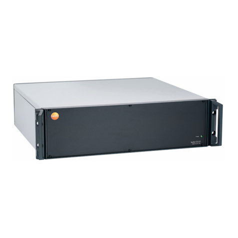
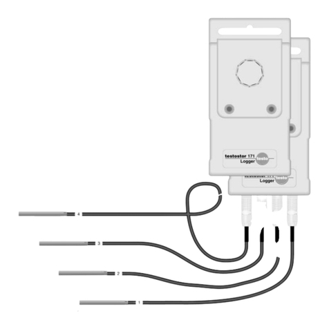
Table of contents
5.4 Disable of radio data sensor or Gateway.............................................20
6Battery / Sensor power supply................................................................. 21
6.1 Lithium battery.....................................................................................21
6.2Modified sensors for power supply test................................................21
7Technical data............................................................................................22
7.1 Radio specific data ..............................................................................22
7.2 Technical specifications for WLAN or Ethernet communication..........23
7.2.1 Ethernet /DHCP ....................................................................23
7.2.2 Ports......................................................................................23
7.3 General data sensors ..........................................................................23

1 About this document
Read these operating instructions carefully and familiarize yourself with the
product before using it
1.1 Usage
•Keep this documentation to hand so that you can refer to it when necessary.
•Please read this instruction manual through carefully and familiarize yourself
with the product before putting it to use.
•Hand this instruction manual on to any subsequent users of the product.
•Pay particular attention to the safety instructions and warning advice in order
to prevent injury and damage to the product.
1.2 Symbols

2 Safety and disposal
Take the testo information document into account (accompanies the
product).
2.1 Warning
Always observe information marked by the following warnings with warning
pictograms. Take the specified precautionary measures!
DANGER
Danger to life!
ATTENTION
Indicates possible property damage
3 System description
The testo Saveris wireless sensors are part of the testo Saveris Solution. As a
stationary measurement technology solution, they are ideally suited for
monitoring temperature and door contacts in cold stores and warehouses. The
wireless sensors are available in various versions and can therefore be flexibly
adapted for numerous applications. Depending on the version, they have an air
temperature sensor, an additional product simulator (mimicking), a door contact
sensor and a penetration probe sensor. The data of the sensors is transmitted
via a Gateway in to the Saveris Restaurant cloud.

The sensors can be integrated into the testo Saveris Food Solution. The data is
recorded at configurable intervals and transferred to the Testo Cloud [Cloud] at
configurable intervals. The customer's WLAN or Ethernet infrastructure is a
prerequisite for transmitting the data (not part of the scope of delivery). The
measured values stored in the cloud can be called up and analyzed at any time
in the corresponding testo Saveris Cockpit [Webbased analysis]. Limit value
violations are immediately displayed on the Control Unit [Operative Control Unit]
or reported by e-mail or SMS.

3.1 System Overview
3.2 Product description
1
article number & name: 0572 2201 XX
description:
radio data logger –ambient temperature
2
article number & name 0572 2202 XX
description:
radio data logger –temperature product
simulation

3
article number & name 0572 2203 XX
description:
radio data logger –door contact
4
article number & name 0572 2204 XX
description:
radio data logger –core temperature
5
article number & name 0572 2204 XX
description:
Gateway
6
article number & name 0554 9320 01
description:
WLAN-communication module
7
article number & name 0554 9330
description:
LAN/PoE-communication module
8
article number & name 0572 2210
description:
radio data logger –wall holder
10
article number & name 0572 2211
description:
radio data logger –holder penetration
probe

3.3 radio data logger –ambient temperature
This sensor measures temperature of its ambient.
3.4 radio data logger –temperature product
simulation
This sensor measures temperature of its ambient as well but provides an
additional calculated temperature measurement value. This calculated value
represents a product temperature value according a calculated/ simulated
behavior.
The product simulator is designed to simulate food thawing and chilled
or frozen food. However, the product simulator does not represent the
core temperature of the food, but simulates the behavior of the food.
3.5 radio data logger –door contact
This sensor is used to detected/observe open or closed doors.
3.6 radio data logger –core temperature
With this sensor it is possible to measure temperature of liquid food, i.e. soups.
Just immerse the metal sensor tip inside the liquid food.

3.7 Gateway button functions & LED
long = 1 sec / periode = 2 sec
short = 200 msec / periode = 400msec
Gateway LED1 Sensor status
Mode
action /
button
Signal
Color
Join Mode
button press <
3 sec
continuously
on
green
new sensor was connected
----
2 x short
blinking
green
30 sensors connected / no more
connections possible
(finished join mode)
----
2 x short
blinking
red
join mode finished -> back to
default
----
off
Receive data from sensor
----
1 x short
blinking
green
default
----
off
Gateway LED2 Network status
Mode
action /
button
Signal
Color
Configuration Mode
(Config XML is saved and
GW connect to Cloud )
connected to
PC via USB-
cable
continuously on
green
Configuration saved and
Connection available
disconnected
from PC
5 sec on
green
No/wrong configuration
----
blinking
continuously short
(200msec/400msec)
red
Connection not available
* Ethernet cable
* no WLAN connection
Network / HW error
----
blinking
continuously long
(1 sec / periode = 2
sec)
red
Communication to Cloud
----
2 x short
green
FW update Over the air
----
alternating long
green/red
factory Reset
button press
> 20 sec
orange

3.8 Radio data logger button functions &
LED
Mode
action / button
Signal
Power down
Sensor switched ON
from power down
button press < 3
sec in state OFF
Blinking for 90 sec 0,2 sec on 0,8
sec off (green) -> sensor is in
manual join mode
In case of finished join mode (max
90 sec)
1x 2 sec green-> Connection to GW
OK
1x 2 sec red -> no Connection to
GW
Sensor Switch OFF
(Sleep Mode)
button press > 3 &
<10 sec in state oN
(Logging)
1 x 0,5 sec green
1 x 0,5 sec red -> sensor go OFF
Power Off / Sleep
Mode (no connection to
Gateway)
button press <
1sec in state sleep
Blinking for 90 sec 0,2 sec on 0,8
sec off (red) -> sensor in roaming
mode
In case of finished join mode (max
90 sec)
1x 2 sec green-> connection to GW
OK
1x 2 sec red -> no connection to
GW
Logging Mode
Only by manual
measure and data
sending
(not during regular
sendings)
button press <
1sec in state sleep
1x 0,2 sec green-> Sensor measure
(direct after press button) Sensor is
in connected state
max after 30 sec:
1x 0,2 sec green-> connection to
GW OK
1x 0,2 sec red -> no ACK from GW
Sensor Switch OFF
(factory reset)
button press
> 30 sec
2 x 0,5 sec green
2 x 0,5 sec red -> sensor go OFF

4 Commissioning
This chapter describes the commissioning of the NSF test set up. The
system is mainly designed to enable NSF to do the certification tests.
The system does not support the whole system UI functionality, which
will be offered to end customers in series. The hardware devices have
already achieved nearly series level. The measurement data of the
devices itself is sent to the original Cloud IoT-core, from where the data
can be displayed via Saveris Restaurant Website.
Additional the software “MTS IoT Core viewer”, allows the user to
display the measurement values on PC and export the data to csv.file.
This software is very limited in its functionality and has only the purpose
to get measurement values from the IoT data base. The UI is simple
and limited.
Measurement and communication cycle is set default by system.
Measurement cycle: 1min
Communication cycle: 1min
4.1 Mounting on the wall
The wall bracket is used to mount the online data logger. Select suitable
mounting materials according to the desired mounting location. The wall mount
can be attached using the supplied adhesive strips. Alternatively, suitable
screws or cable ties can also be used (not included in the scope of delivery).
DANGER
Danger to life!
Electrical lines can be damaged.
-When fixing the wall bracket by means of screws, do not mount directly
on electrical equipment.
When using adhesive strips, make sure that the substrate is clean and
free of grease.
4.2 Mounting of communication module to
the Gateway

4.2.1 WLAN module and PoE module
Before connecting the gateway to the PC or to power supply, the
communication modules must be mounted to the gateway first.

4.2.2 Power supply / batteries
In general, the Gateway runs without any batteries. It needs a continuous 5V
DC/2A power supply.
Additionally, the gateway has a battery compartment. Batteries are only relevant
for customers, which follow a disaster recovery plan, to ensure, that in any case
of power loss, that gateway still works. Basically, the gateway does not store
any measurement values. If the power is down, measurement values are stored
in the sensor, if they can’t be forwarded to the gateway due to power loss.
4.3 Configuration of the Gateway
In case of using WLAN, make sure that a stable WLAN connection is
available before you start configuring the gateway,
In case of using Ethernet, make sure that the Ethernet connection of
the Gateway to the cloud is not blocked by internal fire walls of the IT.
See chapter 7.
4.3.1 Account / Saveris Connect Key
The Account ID/Saveris Connect Key is the unique address of your user
account in the Testo cloud. This connect key is needed to configure the
Gateway in order to ensure that the Gateway sends your data to the correct
user account.
4.3.2 NSF-certification account
The user account is defined by an email-address:
Account
Saveris Connect
Key / Account-ID
testo.qsr+nsf.ws[email protected]
DW-K4-LM-Q3-int0
Password is sent separately!

4.3.3 Gateway offline configuration
The Gateway can be configured via a PDF form.
Note You need the Adobe Reader program (version 10 or later) to use the PDF
form correctly. If you have not installed Adobe Reader, you can go to the
following address to download it free of charge: http://get.adobe.com/reader/.
1. Connect the Gateway with mounted WLAN module to the PC.
2. Open the file NetConf.pdf on the external drive in the Windows-Explorer.
3.Enter the Saveris Connect Key into the Account ID field
4. Enter the local WLAN Network name (SSID) and, if necessary, your WLAN
password in the relevant fields on the PDF form.
5. Click on the Save configuration button. A dialogue box opens for exporting
the form data.
6. Select the external Gateway drive as the storage location and save the form
data (configuration file WiFiConf_Daten.xml) on it.
7. Disconnect the USB connection from the PC to complete the configuration of
the logger.
You can also save the configuration file locally on your computer and
configure other Gateways even faster by simply copying the XML
configuration file onto their external drive.
8. Connect the Gateway with USB-cable to external power adapter.
Do not use the Laptop for power supply.
9. After powering up the Gateway again, the Gateway starts connection to the
cloud.

1
2
4
3

4.4 Connecting a radio data logger
Before you connect a radio data logger to Gateway, please ensure, that
the Gateway is connected to the cloud. You can check the with Saveris
Restaurant Website. See chapter 5!
1. Press the button on the Gateway <3 sec. -> Sensor LED is on and Gateway
is in connect/ join mode!
2. Press the button on the radio logger for < 3 sec in State OFF.
-> Blinking for 90 sec 0,2 sec on 0,8 sec off (green)
-> sensor is in manual join mode
In case of finished join mode (max 90 sec) LED flashes 1x 2 sec green
-> Connection to GW OK
3. Gateway Network LED goes off
4. Connection is established and Sensor is visible with its serial number in the
Software on the “Online Logger page”.
5
8
7

5.1.2 Saveris Restaurant Online/ Radio data logger
website
By selecting the Online data logger page, you get to the radio data logger and
dashboard.
5.1.3 Measurement curves
Measurement curves can be displayed by pressing the three dots
or select page stationary measurements in the Analysis field
This manual suits for next models
4
Table of contents
Other TESTO Data Logger manuals