Tenma 21-10130 UK+EU User manual

www.element14.com
www.farnell.com
www.newark.com
www.cpc.co.uk
TM
TM
Page <1> V1.023/08/18
2 in 1 SMD Rework Station
21-10130 UK + EU
User Manual

www.element14.com
www.farnell.com
www.newark.com
www.cpc.co.uk
TM
TM
Page <2> V1.023/08/18
Please read this manual before operating the equipment.
Keep manual in accessible place for future reference.
What’s Included
Control Unit 1 No.
Soldering Iron 1 No.
Soldering Iron Holder 1 No.
Nozzle 1 No.
Bracket 1 No.
Power Cord (UK + EU) 2 No.
Cleaning Sponge 1 No.
User Manual
Safety Precautions
• This product is meant for use by trained and qualied personnel only. Keep away from children
• Do not dis-assemble the control unit. There are no user serviceable parts
• Do not use the rework station in the vicinity of ammable material
• Use appropriate safety gear and exercise caution while using this rework station
• Do not touch the soldering tip or hot-air nozzle as the temperature can be 200°C to 400°C when in use
• Please pay attention to the specications of the power supply and use proper power cord
• For changing the soldering tip, ensure that the power supply is turned off and allow sufcient time for the tip to cool down.
• The soldering tip should be cleaned by wiping it on the cleaning sponge provided. This will help get rid of the burnt solder
or uxes that cause oxidation on the soldering tip. Not cleaning the tip might lead to improper soldering.
• Never use it as a hair drier and touch the heating element or blow the skin directly
• Don’t operate with wet hands or wet wire in order not to result in short circuit or electronic shock
• Please use the nozzle offered by manufacture and don’t replace the original nozzle
• Temperature will vary from the models of the nozzles, which is normal
• Don’t use this device to do other work except soldering
• Don’t rap the handle to remove the doss of tip, which is bad for it
• Don’t pull the cable but hold tightly the plug when you take out of plug
• Please keep good ventilation because there is smoke when solder
Specications
Input Voltage 220V AC 50Hz
Total Power 900W Max. Air heating: 800W Max, Pump: 40W
Soldering Iron: 50W
Temperature Range Hot Air Rework Station 100°C to 500°C
Soldering Station 200°C to 480°C
Temperature Unit °C / °F Convertible
Temperature Controlling Stability Static ±2°C

www.element14.com
www.farnell.com
www.newark.com
www.cpc.co.uk
TM
TM
Page <3> V1.023/08/18
Temperature Controlling Accuracy Static ±10°C
Calibration Range Celsius 50°C to -50°C
Fahrenheit -58°F to 122°F
Setting Storage (3 groups) Hot Air Rework Station 200°C, 40% ow; 300°C, 60% ow;
400°C, 80% ow
Soldering Station 200°C; 300°C; 400°C
Range of Air Volume Hot Air Rework Station 020 - 100 level
Dormancy and Standby Hot Air Rework Station Stopping heating, air-blowing delay and then
be in the condition of dormancy and Standby
Cold Air Hot Air Rework Station Air-blowing made by the machine and
stopping heating
Malfunction Alert Heating Elements Displaying H-E
Sensor Displaying H-E
*Specications are subject to change without prior notice.
Function diagram
1 Rework station nozzle
2 Hot-air handle bracket
3 Hot-air handle button group
4 Rework station handle
5B screen to display working
station of soldering stations
6Output of hot-air
7 Function button groups
8 Output of soldering station
9 Iron holder
10 Sponge for clean iron
11 Iron handle
12 Power switch
13 A screen to display working
station of soldering stations

www.element14.com
www.farnell.com
www.newark.com
www.cpc.co.uk
TM
TM
Page <4> V1.023/08/18
Interchangeable soldering tips of soldering station
900M tip OutDiam Φ6.5
Nozzles

www.element14.com
www.farnell.com
www.newark.com
www.cpc.co.uk
TM
TM
Page <5> V1.023/08/18
Characteristics
• MCU computer offers PID advanced algorithms industrial control with thermo-control and thermo-stability, which makes
more exactly control temperature
• Dual LCD screen respectively and separately display the working state and parameter, which is very directly. So customer
can understand the output state at a glance
• Temperature rapidly rises with large output power
• High ow diaphragm pump suitable for varies of nozzles to de-solder SMD components
• Dormancy, automatic shutdown and other power-saving features
• Shortcut keys on the handle make it more convenient for the user to adjust temperature and air volume
• Three groups of storage functions can bring very fast mode of switching different groups of temperature and hot-air volume
to the customers
• All units are equipped with temperature compensation, which ensure stable state of operation
• Indicator for malfunction alert.
Warning
• This tool be placed on its stand when not in use. The instructions for heat guns and hand-held paint strippers shall include
the substance of following:
• A re may result if the appliance is not used with care, therefore be careful when using the appliance in places where there
are combustible materials:
• Do not apply to the same place for a long time
• Do not use in presence of an explosive atmosphere
• Be aware that heat may be conducted to combustible materials that are out of sight
• Place the appliance on its stand after use and allow it to cool down before storage
• Do not leave the appliance unattended when it is switched on
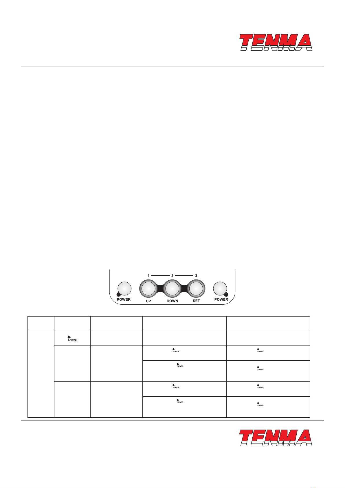
Button instructions
Position Knob/Button First function Second function
(short press < 5s)
Second function
(long press > 5s)
Front
Panel
Buttons
Work and shutdown
of the rework station Group Group
UP Value increasing
Press with knob and then se-
lect hot-air quick key 1 to set.
Press with knob and deposit
the setting of hot-air quick knob 1
Press with knob and then
select soldering station quick key
1 to set.
Press with knob and deposit
the setting of iron quick knob 1
DOWN Value decreasing
Press with knob and then se-
lect hot-air quick key 2 to set.
Press with knob and deposit
the setting of hot-air quick knob 2
Press with knob and then
select soldering station quick key
2 to set.
Press with knob and deposit
the setting of iron quick knob 2

www.element14.com
www.farnell.com
www.newark.com
www.cpc.co.uk
TM
TM
Page <6> V1.023/08/18
Position Knob/Button First function Second function
(short press < 5s)
Second function
(long press > 5s)
Front
Panel
Buttons
SET
Set temperature and
conrmation varies
of settings
Press with knob and then se-
lect hot-air quick key 3 to set.
Press with knob and deposit
the setting of hot-air quick knob 3
Press with knob and then se-
lect hot-air quick key 3 to set.
Press with knob and deposit
the setting of iron quick knob 2
Work and shutdown
of soldering station Group Group
Hot-air
station
Front
Panel
Buttons
handle
knob
UP To increase the Set value of hot-air station
DOWN To decrease the Set value of hot-air station
Adjustment of air
volume Blowing cold air of rework station Awake hot air of rework station
Installation
The brackets for the handles must be installed when operating for the rst time.
Please see the following illustration:
1. Please x the bracket by tightening the four screws according to the illustration and your personal habit.
2. According to your selection, dismantle the two screws on the left or the right, which x the bracket of the handle.
3. Place the two installation hole of the bracket to the two xed screw holes of the machine, and then tighten the dismantled two
screws. Put the components of the handle on the bracket to check if it is suitable.
Introduction for LCD display
Description for LCD display
• Display “- - -” means the device is standby
• Screen “A” displays the working state of rework station.
• “P_ _” eans rework station is under the normal setting condition.

www.element14.com
www.farnell.com
www.newark.com
www.cpc.co.uk
TM
TM
Page <7> V1.023/08/18
• “ P 0 1 “ means rework station is under the condition set by memory group 1.
• “ P 0 2 “ means rework station is under the condition set by memory group 2.
• “ P 0 3”means rework station is under the condition set by memory group 3.
• Both screen A and screen B display “ OFF” in the memory temperature area 2, which means the device, is standby.
• When the temperature area shines °C/°F the station is under the condition available to set.
Power
Upon power on the unit, the reworking station and soldering station be standby.
1. REWORK STATION
1. Power on: Rework station start to work after press the “POWER” knob at the left of panel.
2. At that time, if the handle is on the bracket, screen “ display state standby (diagram 3), or display the setting temperature
and 3 seconds later it display the actual temperature (diagram 4, diagram 5).
3. Temperature Settings
In normal condition, there are two methods to set temperature of hot-air reworking station.
A. If screen A shines °C/°F setting temperature through operating the button of panel. If screen A doesn’t shine °C/°F you must
press the “SET” button to switch to shine °C/°F of screen A then the station
Under the setting condition. Then you can press “SET” button to set hot -air rework station’s temperature and the main
temperature area shines the setting temperature, you can press UP knob or DOWN knob to adjust the setting temperature.
4s-no-press or press SET knob, you can keep the temperature and quit out this setting. (Diagram 6).
A. Setting temperature via handle of rework station. You can press UP knob or DOWN knob directly to adjust temperature and
the main temperature area indicators setting temperature. 4s-no-press or press SET knob, you can keep the temperature
and quit out this setting, at that time, you can adjust hot-air volume by pressing “ ” Whether screen A or screen B shine °C/°F
as you set, the device is under the setting condition and shining area for °C/°F switch to screen “A “ automatically.
Notice: continually pressing UP or DOWN knob in long time will quickly adjust the temperature, at that time, the screen don’t
shine. (Same as below description)

www.element14.com
www.farnell.com
www.newark.com
www.cpc.co.uk
TM
TM
Page <8> V1.023/08/18
4. Hot-air volume settings
In normal working condition, there are two methods to set hot-air volume:
A. If screen A shines setting °C/°F temperature through operating the button of panel. If screen A doesn’t shine °C/°F you
must press the “SET” button to switch to shine °C/°F of screen A then the station under the setting condition. Then you can
press “SET” button to set hot-air rework station’ s temperature and the main temperature area shines the setting tempera-
ture, you can press UP knob or DOWN knob to adjust the setting temperature. 4s-no-press or press SET knob, you can
keep the temperature and quit out this setting (diagram 7).
B. Setting hot-air volume via handle of rework station. You can press UP knob or DOWN knob to adjust hot-air volume and
the main temperature area indicators setting volume. 4s-no-press or press SET knob, you can keep the volume and quit
out this setting, at that time, you can adjust hot-air volume by pressing “ ” When the screen A or screen B shine °C/°F as
you set, the device is under the setting condition and shining area for °C/°F switch to screen”A” automatically
5. Storing the Temperature values
Under normal working condition, hold down POWER knob at the left of panel, at the same time long press (>5s) the UP knob or
DOWN or SET to adjust temperature and air volume to the required values separately in term 1 or term 2 or term 3. But when
you hold down POWER knob at the left of panel and short press (<5s) UP or DOWN or SET knob to use the storage setting
temperature and air volume into current work temperature and air volume (diagram8, diagram9, diagram10).
(Notice: up, down, set refer to storage term 1, term 2, term 3)

www.element14.com
www.farnell.com
www.newark.com
www.cpc.co.uk
TM
TM
Page <9> V1.023/08/18
6. Temperature comp temperature and calibration
Under normal working condition, hold down both POWER knob at left of panel and “ ” knob on the handle to calibrate. Screen
A will display the character CAL, and temperature value can be calibrated by pressing UP or DOWN knobs. Pressing the SET
knob to conrm storage and quit from this calibration (diagram 11).
7. Dormancy
Under normal working condition, when the user put the handle on the bracket, then the equipment will be automatically switch
to the dormancy condition and the heater also stops heating. This happens in the case when the temperature is higher than
100°C, during the hot-air station dormancy period the screen A display character SLP (diagram 3)
8. Conversation between cold-air and hot-air
In normal condition, continually press “ “knob twice and then make the hot-air be in the state of cold-air blow (diagram12).
Under the cold-air condition, press “ ” knob once, recover the hot-air working condition.
9. Standby
Under normal working condition, the device keep the current temperature and air volume and cut down heating to the rework
station after pressing POWER knob at the left of panel (diagram 1A), below 100°C, the device is standby (diagram1). If power
is off, the soldering station is off, whole device will be off after the temperature below 100°C.
10. Error/Fault indication
1. When “H-E” is displayed on the screen A, there is no hot air in the nozzle (diagram13), which indicates that the heating
element fails.
2. When “S-E” is displayed on the screen A, there is a fault in sensor (diagram14), which signies that there is something
wrong with the sensor or the related circuit of the sensor.

www.element14.com
www.farnell.com
www.newark.com
www.cpc.co.uk
TM
TM
Page <10> V1.023/08/18
II. SOLDERING STATION
1. Power on
Screen B which displays actual temperature in 3s displays setting temperature after pressing POWER knob at the right of
panel (diagram15, diagram16).
2. Temperature setting
In normal working condition, if screen B shines °C/°F or you at rst continually press SET knob twice to switch to shine °C/°F,
then press the UP or DOWN knob to adjust temperature. Screen B shines”SET” and the main temperature area shines the
setting temperature of soldering station. Stopping pressing knob or pressing SET knob conrm and keep settings and quit from
this operation (diagram17).
3. Shortcut keys set storage
Under normal working condition, hold down POWER knob at the left of panel, at the same time long press (>5s) the UP knob
or DOWN or SET to adjust temperature to the required values separately in term1 or term2 or term3. When you hold down

www.element14.com
www.farnell.com
www.newark.com
www.cpc.co.uk
TM
TM
Page <11> V1.023/08/18
POWER knob at the left of panel and short press (<5s) UP or DOWN or SET knob to use the storage setting temperature into
current work temperature and air volume.
(Notice: up, down, set refer to storage term1, term2, term3)
4. Temperature comp temperature and calibration
Under normal working condition, hold down both POWER knob at right of panel and “ ” knob on the handle to calibrate
soldering station temperature (diagram18). Temperature value can be calibrated by pressing UP or DOWN knobs. Pressing the
SET knob to conrm storage and quit from this calibration (diagram 11).
5. Standby
In normal working condition, press POWER key at the right of panel to make the device be standby (diagram 2). Make the
power off, at the same time, the soldering station is off and the whole station will off when the temperature is low to 100°C.
6. Error/Fault indication
A. When “H-E” is displayed on the screen A, there is no temperature (diagram 19),which indicates that the heating element
fails.
B. When “S-E” is displayed on the screen A, there is a fault in sensor (diagram 20), which signies that there is something
wrong with the sensor or the related circuit of the sensor.
III. Conversion of temperature unit
Under the power off condition, hold down the UP, DOWN and SET knob and then put power on to switch °C/°F.

www.element14.com
www.farnell.com
www.newark.com
www.cpc.co.uk
TM
TM
Page <12> V1.023/08/18
IV. Replacement of heater
Please follow the following steps for the successful replacement of the heating element of hot-air rework station:
A. Cut down power, please refer to the following diagram to replace heater after it is cool.
B. Based on diagram, loosen the three screws of the handle.
C. Dismantle the upper cover of the handle, pull out the ground wire on the duct and take out the fan.
D. Take out the heating element from PCB board.
E. Insert new heating element in PCB board, pay attention to install properly.
F. Install it as the contrary method of remove.
Please follow the following steps for the successful replacement of heating element of soldering station:
A. Cut down power; replace the heating element after it is cool.
B. As following diagram, unscrew the nut 1, take out the stainless steel cap 2 and iron tip 3, then unscrew the xed holder 4,
desoldering the heating element 5.
C. Replace the good condition heating element and install it as the contrary method of remove.
V. Soldering Tip Care and Use
a. Tip Temperature
• High soldering temperatures can degrade the tip
• Use the lowest possible soldering temperature. The excellent thermal recovery characteristics ensure efcient and effective
soldering even at low temperatures
• When not in use, do not leave the soldering iron on at a high temperature as the tip’s solder plating will get covered by oxide,
reduction it’s heat conductivity

www.element14.com
www.farnell.com
www.newark.com
www.cpc.co.uk
TM
TM
Page <13> V1.023/08/18
Important Notice : This data sheet and its contents (the “Information”) belong to the members of the Premier Farnell group of companies (the “Group”) or are licensed to it. No licence is granted
for the use of it other than for information purposes in connection with the products to which it relates. No licence of any intellectual property rights is granted. The Information is subject to change
without notice and replaces all data sheets previously supplied. The Information supplied is believed to be accurate but the Group assumes no responsibility for its accuracy or completeness, any
error in or omission from it or for any use made of it. Users of this data sheet should check for themselves the Information and the suitability of the products for their purpose and not make any
assumptions based on information included or omitted. Liability for loss or damage resulting from any reliance on the Information or use of it (including liability resulting from negligence or where the
Group was aware of the possibility of such loss or damage arising) is excluded. This will not operate to limit or restrict the Group’s liability for death or personal injury resulting from its negligence.
Tenma is the registered trademark of the Group. © Premier Farnell Limited 2016.
b. Cleaning
• Clean the tip regularly with a cleaning sponge, as oxides and carbides from the solder and ux can form impurities on the
tip. These impurities can result in defective joints or reduce the tip’s heat conductivity
• When using the soldering iron continuously, be sure to loosen the tip and remove all oxides at least once a week. This helps
prevent seizure and reduction of the tip temperature
• After use, wipe the tip clean and coat with fresh solder. This helps prevent tip oxidation
VI Changing the Soldering Tip
a. Always turn the power OFF when removing or inserting a soldering tip
b. Let the tip to cool down to room temperature before holding it with heat resistant pads
c. Loosen nut (1 in diagram 7)
d. Pull out the shaft of the soldering iron (2 in diagram 7)
e. Remove the old soldering tip and replace with new one (3 in diagram 7)
f. Reverse the process to secure the soldering tip
g. Preferred Soldering Tips : 21-10140, 21-10142, 21-10144, 21-10146, 21-10148, 21-10150, 21-10152, 21-10154,
21-10156, 21-10158
Other manuals for 21-10130 UK+EU
1
Table of contents
Other Tenma Rework Station manuals