Velleman VTSDIR User manual

V
I
N
U
S
V
TS
D
N
FRA-R
E
S
ER MAN
D
I
R
E
D SMD
&
UA
L
&
BGA R
E
E
WORK
S
3
S
TATIO
N
N

VTSDIR
21.03.2011 ©Velleman nv
2
Main station front panel
Main station rear panel
Figure

21
1
.
T
o
I
m
Th
th
e
Th
co
m
Pl
e
ke
e
F
o
w
e
2
.
1.
2.
3.
4.
5.
6.
7.
8.
9.
10
T
o
1.
2.
3.
4.
5.
6.
7.
•
•
•
.03.2011
.
Introd
u
o
all reside
n
m
portant e
n
This
s
harm
be ta
k
to a l
o
If in
d
ank you for
e
device wa
s
is appliance
m
ponents.
e
ase read th
e
p this man
o
r more inf
o
e
bsite ww
w
.
Safety
I
Warning an
d
significant
s
Ensure th
Check ca
r
Put the p
r
resistant
m
During th
e
Use glov
e
Do not us
Turn the
p
or prior t
o
Keep the
amount o
f
use any s
Quartz h
e
This unit
i
used for
a
.Keep the
play with
o
prevent e
l
Make sur
e
Do not pr
e
Do not b
u
damage t
h
To isolate
electric s
h
Do not e
x
Turn the
p
will remai
Do not m
o
W
a
This syste
other purp
o
The IR ha
n
without bei
hand tool,
e
not switch
t
may resul
t
Do not ai
m
or via mirr
o
u
ction
n
ts of the
E
n
vironmen
t
s
ymbol on t
h
the environ
k
en to a spe
o
cal recyclin
d
oubt, con
t
buying the
V
s
damaged i
n
is specially
is manual c
a
ual readily
a
o
concerni
n
w
.velleman
I
nstruct
:
W
d
Caution a
r
s
afety conce
r
e voltage ra
r
efully of an
y
r
oducts on a
m
aterial du
e
e
operation,
e
s and/or an
y
e the produ
c
p
ower switc
h
o
storing th
e
appliance cl
e
f
liquid dete
olvent to cl
e
e
ater is fragi
i
s designed
f
a
ny other pu
unit out of t
the applian
c
l
ectrical sh
e
the unit is
e
ssure the
A
u
mp, hit, po
u
h
e quartz h
e
the equipm
h
ock. This
m
x
pose the un
p
ower switc
h
n unused fo
o
dify the un
i
a
rnings
m is desig
n
o
se without
c
n
d tool is d
ng allowed
t
e
nsure that
t
he IR Hand
t
in damag
e
m
the IR h
a
o
r) to shine
i
E
uropean U
n
t
al informa
t
h
e device or
ment. Do n
o
cialized co
m
g service. R
e
t
act your l
o
V
TSDIR! Pl
e
n
transit, do
designed fo
r
a
refully to
m
a
ccessible fo
n
g this pro
d
.eu.
ions
W
ARNIN
G
r
e positione
d
r
ns. Be sure
ting of the
u
y
damage d
u
safe and st
a
e
to the unit
the heater
y
heat resis
t
c
t near com
b
h
OFF and a
l
e
unit.
e
aning espe
rgent. Neve
r
e
an the case
le, be slight
l
f
or SMD re
w
rpose witho
he reach of
c
e.
ock, be su
r
grounded.
A
A
C power co
r
u
r water/liq
u
e
ater.
ent from th
e
m
ay result in
it to moistu
r
h
off and re
m
r a longer p
e
i
t.
n
ed to be u
c
onsulting
m
esigned fo
t
o cool. It s
h
it is placed
b
tool on whi
l
e
to the IR
a
nd tool at
y
i
nto the eye
s
Us
e
n
ion
t
ion about
t
the packag
e
o
t dispose o
f
m
pany for re
c
e
spect the l
o
o
cal waste
e
ase read th
not install o
r
r
SMD/BGA
m
aximize the
r reference.
d
uct and th
G
and CA
U
d
at critical
p
to comply
w
u
nit and you
u
ring transp
o
a
ble workin
g
can reach
v
is extremel
y
t
ant tools to
b
ustible gas
e
l
low the hea
cially the q
u
r
submerse
t
.
l
y moving t
h
w
ork, BGA re
ut first cons
children. Yo
r
e to take t
A
lways conn
e
r
d. Be sure
t
u
ids or othe
r
e
mains bef
o
Death or se
r
e nor use t
h
m
ove the A
C
e
riod of tim
e
sed for sol
d
m
anufacture
r
r intermitt
e
h
ould be use
b
ack in its c
o
l
e it is in th
e
hand tool
o
y
our eyes.
s
as serious
VTSDIR
3
e
r ma
n
t
his produ
c
e
indicates t
h
f
the unit (o
r
c
ycling. This
o
cal environ
disposal a
u
e manual th
o
r
use it and
c
rework and
advantage
s
e latest ve
r
U
TION
p
oints in the
w
ith the foll
o
r mains po
w
o
rtation.
g
table. Tabl
v
ery high te
m
y
hot, and w
i
pick up the
e
s or flamm
ter to cool
b
u
artz heater.
t
he unit in li
h
e station if
n
-balling and
ulting the
m
ung Childre
n
he followi
n
e
ct power t
o
t
he work ar
e
r
wise subjec
t
o
re commen
rious injury.
h
e unit with
C
power cor
d
e
.
d
ering/de
s
r
or its agen
t
e
d use onl
y
d a maximu
o
oling stand
e
cooling sta
o
r the cool
Do not allo
w
eye damag
e
n
ual
c
t
h
at disposal
r
batteries)
a
device sho
u
mental rule
s
u
thorities.
o
roughly be
f
c
ontact your
also very c
o
s
of using y
o
r
sion of thi
:E
L
manual to
d
o
wing warni
n
w
er supply is
e surface s
h
m
perature a
n
i
ll cause ser
i
PCB assem
able materi
a
b
efore check
This may b
quid or allo
w
n
ecessary.
pre-heatin
g
m
anufacturer
n
should be
n
g precauti
o
o
a grounde
d
e
a is well ve
n
t
the heatin
g
cing repairs
wet hands.
d
by pulling
t
s
oldering S
t
s.
y
. It is not d
e
m of 5 min
u
to cool do
w
nd. Fail to
c
ing stand.
w
the IR spo
t
e
may occu
r
of the devi
c
a
s unsorted
u
ld be retur
n
s
.
f
ore bringin
g
dealer.
o
nvenient fo
r
o
ur new SM
D
s user ma
n
L
ECTRIC
A
d
raw the us
e
n
gs and cau
t
identical pr
h
ould be con
n
d potential
l
i
ous burns i
f
bly to elimi
n
a
ls.
ing or repla
c
e used with
w
any liquid
g
PCB asse
m
or its auth
o
supervised
t
o
ns:
d
receptacle
.
n
tilated.
g
surface to
or making
a
t
he plug (no
t
MDs and sh
e
signed to
b
u
tes before
c
w
n between
r
c
omply wit
t
from the I
R
r
.
c
e after its li
f
municipal
w
n
ed to your
d
g
this device
r
re-balling
s
D
/BGA rewo
n
ual, pleas
e
A
L SHOC
K
e
r’s attentio
n
t
ions for yo
u
ior to use.
sisted of fir
e
l
y dangerou
s
f
contacted
e
n
ate the pos
s
c
ing heater
a
a damp clo
t
to enter th
e
m
bly and sho
o
rized agent
.
t
o ensure th
a
.
physical sh
o
a
ny mainten
t
the cable)
ould not be
b
e used cont
c
ooling. Afte
r
ework oper
a
h there ins
R
hand tool
©Vellema
n
f
ecycle coul
d
w
aste; it sho
u
d
istributor o
into service.
s
maller BGA
rk system a
e
visit our
K
n
to
u
r safety.
e
and heat
s
.
e
xposed ski
n
s
ibility of b
u
a
nd other p
a
t
h using sm
a
e
station. Ne
uld not be
.
a
t they do
n
o
ck. This m
a
ance to avo
i
when the u
n
used for an
y
inuously
r
using the
I
a
tions. Also,
tructions
(either dire
c
n
nv
d
u
ld
r
If
nd
n
.
u
rns.
a
rts,
a
ll
ver
n
ot
a
y
i
d
n
it
y
I
R
do
c
tly

21
•
•
•
•
3
.
Re
•
•
•
•
4
.
Re
M
a
1.
2.
3.
4.
5.
6.
7.
8.
9.
10
M
a
11
12
13
14
15
16
M
a
17
18
19
20
21
5
.
Th
op
H
o
so
l
M
e
N
o
Pr
o
.03.2011
The syste
m
pre-heater,
for the equ
Death or
s
equipment
Do not all
o
result. Due
Keep this d
.
Genera
fer to the V
e
Familiarise
All modific
a
device is n
o
Only use t
h
Damage ca
dealer will
n
.
Overvi
e
fer to the ill
a
in station
SOLDERL
I
Time cou
n
“▼” key:
“▲” key:
IR Tempe
Celsius (°
Fahrenhe
i
“
RESET”:
“
TIMER”
d
.
“
ALARM”:
a
in station
.“▲” key:
T
.“▼” key:
T
.
“
MODEL”:
.Fahrenhe
i
.Celsius (°
.Preheat t
e
a
in station
.Solderlig
h
.DC12V C
o
.Output to
.Fuse Hold
.AC power
.
Workin
e most com
erating tem
p
o
wever, to
m
l
ders that r
e
e
lting point
o
rmal Opera
t
o
duction Lin
e
m
can prod
to contact
e
ipment to c
o
s
erious inj
u
from the m
a
o
w the spil
to the use
o
evice away
f
l Guideli
e
lleman®
S
Indoor us
e
Keep this d
e
Protect this
yourself wit
a
tions of the
o
t covered b
h
e device fo
r
used by dis
r
n
ot accept r
e
e
w
ustrations o
– solderlig
I
GHT/Timer
n
ting switch
:
Time count
Time count
rature displ
a
C): IR Tem
p
i
t (°F): IR T
e
Offset forw
a
d
isplay: Tim
e
alarm indic
a
– Preheat
s
Temperatur
e
Temperatur
e
Actual tem
i
t (°F): Pre-
h
C): Pre-hea
t
e
mperature
- rear pan
e
h
t Foot switc
o
oling fan s
o
PREHEATE
R
er
inlet (Main
s
g
Temp
e
mon solderi
n
p
erature of
t
m
eet RoHS r
e
e
quire a wor
k
t
ion
e
Operation
uce a lot o
f
e
xposed ski
n
o
ol before c
o
u
ry may re
s
a
ins before
c
lage of an
y
o
f glass opti
c
f
rom childre
nes
S
ervice an
d
e
only. Kee
p
e
vice away
f
device from
h the functi
o
device are
f
y the warra
n
r
its intende
d
r
egard of ce
r
e
sponsibilit
y
n page 2 of
ht section
alternate s
w
:
I = time c
o
ing / Actual
ing / Actual
a
y / IR han
d
p
erature in
d
e
mperature
a
rd counting
e
counting
d
a
tor
s
ection
e
pre-heate
r
e
pre-heate
r
perature off
s
h
eater temp
t
er tempera
t
setting disp
l
e
l
h socket (4
o
cket (3 pin)
R
s
inlet)
e
rature
n
g alloys us
e
t
his type of
s
e
quirements
k
ing temper
a
f
heat. Do
n
n
as burning
o
mmencing
m
s
ult from el
c
ommencing
y
liquid to f
a
c
al compon
e
n and unau
t
d
Q
uality
W
p
this device
f
rom dust a
n
shocks and
o
ns of the d
e
f
orbidden fo
n
ty.
d
purpose.
U
r
tain guideli
n
y
for any en
s
this manual
w
itch: I = S
o
o
unting up,
temperatur
e
temperatur
e
d
tool power
d
egrees Cels
in degrees
F
for “TIMER
”
d
isplay / Pro
c
r
up (increa
s
r
down (dec
r
s
et pre-hea
t
erature indi
c
t
ure in degr
e
l
ay (3 segm
e
pin)
e
d in the el
e
s
older is de
t
, these sold
e
a
ture which
le
a
21
5
270-32
320-38
VTSDIR
4
n
ot allow th
e
may occur.
m
aintenanc
e
ectric sho
c
repairs.
a
ll on the
q
e
nts, the IR
t
horized use
W
arranty on
away form
n
d extreme
h
abuse. Avo
e
vice before
r safety rea
s
U
sing the de
v
n
es in this
m
s
uing defect
s
.
o
lderlight te
m
O= time c
o
e
decrease
e
increase
ius indicato
r
F
ahrenheit i
n
”
c
ess timer
s
e)
r
ease)
t
er
c
ating light
e
es Celsius
i
e
nts)
e
ctronics ind
t
ailed below
e
rs are no l
o
is ±30°C (
5
a
ded solder
5
°C (419°F
)
0°C (518-6
0
0°C (608-7
1
e
IR spot fro
m
To eliminat
e
.
c
k. It is ther
e
q
uartz emi
t
hand tool s
h
rs.
the last pa
g
rain, moistu
h
eat.
id brute for
c
actually usi
s
ons. Dama
g
v
ice in an u
n
m
anual is no
t
s
or proble
m
m
perature c
o
unting dow
n
r
n
dicator
i
ndicator
ustry consis
and can va
r
o
nger allowe
5
4°F) higher
)
0
8°F)
1
6°F)
m
the IR ha
e the possi
b
e
fore essen
t
t
ter (pre-he
a
h
ould be ha
n
g
es of this
m
re, splashin
g
c
e when ope
ng it.
g
e caused b
y
n
authorised
t
covered b
y
m
s.
ontrolled, O
n
t of 60% tin
r
y from man
d and are r
e
.
30
0
36
0
nd tool or I
R
b
ility of burn
t
ial to isolat
e
a
ter) as da
m
n
dled with r
e
m
anual.
g
and drippi
rating the d
e
y
user modi
f
way will voi
d
y
the warran
= time cou
and 40% l
e
ufacturer to
e
placed by l
e
lead-fre
220°C (42
8
0
-360°C (57
2
0
-410°C (68
0
©Vellema
n
R
from the P
s
, allow tim
e
e
the
m
age may
e
asonable ca
ng liquids.
e
vice.
f
ications to
t
d
the warra
n
ty and the
nting.
e
ad. The
manufactu
r
e
ad-free
e
8
°F)
2
-680°F)
0
-770°F)
n
nv
CB
e
re.
t
he
n
ty.
r
er.

VTSDIR
21.03.2011 ©Velleman nv
5
6. Setup
Refer to the illustrations on page 2 of this manual.
Note: never unplug any connection during operation.
•The equipment must be sited on a firm surface at least 1.2M x 0.75M and at a height to suit the operator.
The location should be chosen to suit the flow of work.
•Plug the solder light plug into the socket on the front of the main station.
•Plug the solder light fan into the cooling fan socket [18] and place the solder light in the holder.
•Plug the footswitch into the foot switch socket [17].
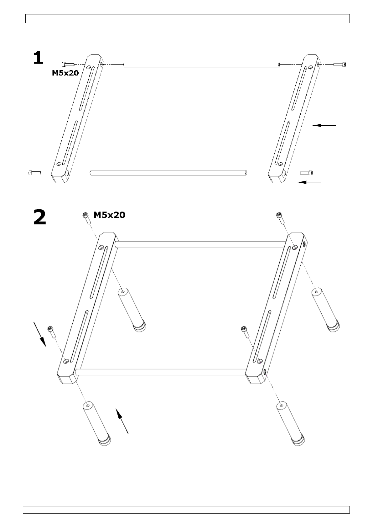
•The quartz heaters are secured against shocks with a metal bar and plastic tubes. Remove these and mount
the metal grid in place (refer to Appendix 1).
•Mount the PCB holder (refer to Appendix 2).
•Plug the power cord into the AC power inlet [21].
7. Operation
•The principle of operation of IR rework system is that whilst being heated from above and below, a single
SMD is subjected to similar temperature/time profile during rework as it experiences during reflow in the
original production process.
Note: wait about 5 minutes for the system to warm up after changing a setting.
IR hand tool operation:
•Set the “SOLDERLIGH/TIMER” switch [1] to the SOLDERLIGHT position (I).
•Set the IR Lamp temperature using the “▼” [3] and “▲” [4] keys. Press and hold ±2s to increase
setting speed. Read the temperature on the display [5].
Note: the temperature depends on the type of work (normally about 240°C)
Standard operation
•Press on the footswitch to start the IR heating; release to stop IR heating.
Timer-up operation
•Set the “SOLDERLIGH/TIMER” switch [1] to the TIMER position (O).
•Set the “Time counting” switch [2] to the UP position (I).
•Press on the footswitch to start IR heating; release to stop IR heating. The timer display [9] will count
the number of seconds that the IR heating was on.
Timer-down operation
•Set the “SOLDERLIGH/TIMER” switch [1] to the TIMER position (O).
•Set the “Time counting” switch [2] to the DOWN position (O).
•Set the timer using the “▼” [3] and “▲” [4] keys. Press and hold ±2s to increase setting speed. Read
the time (in seconds) on the display [9].
•Press on the footswitch to start IR heating; release to stop IR heating. The timer display will count
down the number of seconds that the IR heating was on. When 000 is reached, a warning signal
sounds.
Notes:
•Press the reset switch [8] to return the display to 000.
•To determine the reflow time of a new component, first use the timer up operation until it reflows, than
use the timer value for timer-down operation.
Pre-heater operation:
•Set the pre-heater temperature using the “▼” [12] and “▲” [11] keys. Press and hold ±2s to increase
setting speed. Read the temperature on the display [16].
Note: the temperature depends on the type of work (normally about 220°C)
Actual temperature compensation value
•Press on the MODEL button [13] until the display shows “---” (±4s). The temperature compensation is
shown for ±2s.
•To change the value, press the MODEL button [13] again. The value on the display starts to flash and
can be set using the “▼” [12] and “▲” [11] keys.
Note: when the display shows “00” or “-00” the compensation is “+10”.
E.g. When the temperature is set at 200°C and the measured temperature is only 190°C, then the
value must be set to “00” or “-00”. If the measured value is 180°C, than the compensation value must
be set to “+10” (-20 + 10 = 10).
General operation:
CAUTION: to avoid burns, do not touch the heater or PCB directly, use clips or tweezers to pick up or align
components.
CAUTION: do not allow water/liquids/solvents to touch the heater surface to avoid temperature drop cracks
while the unit is still hot. Such cracks can lead to electrical shorts or failure of the heater.
CAUTION: Do not touch the PCB holder to avoid burning your skin during preheat!

21
P
T
8
.
•
•
•
.03.2011
P
reparatio
n
The proced
•Switc
h
•Set ‘c
o
•Sort t
o
The followi
n
•SMT T
w
•Flux d
i
•Low s
o
T
emperatu
r
In normal
o
system is d
150W shor
t
maximum
o
In normal
u
provided b
y
Soldering
•PREPAR
A
centre
o
thickne
s
apply s
o
o[A]
P
o[B]
R
the c
duri
n
phas
e
o[C]
S
o[D]
C
Desolderi
n
•PREPAR
A
centre
o
o[A]
P
o[B]
R
the c
duri
n
time
o[C]
S
o[D]
C
Aftercare
•Clean fl
u
•Check s
o
•Test
.
Q&A
What Top
H
Betwee
n
What’s the
Approxi
m
Move th
compon
e
What pre-h
Betwee
n
n
ure for prep
h
on and wa
r
o
ntrol settin
g
o
ols and flu
x
n
g tools are
w
eezers, fin
i
spenser bo
t
o
lids and gel
r
e profile
o
peration th
e
esigned for
t
wave IR la
m
o
f 650W me
d
u
se, approxi
m
y
the back h
A
TION: plac
o
f the PCB p
r
s
s). Place an
o
lder paste t
o
P
REHEAT th
e
R
EFLOW: us
e
omponent u
n
g the reflo
w
e
time (nor
m
S
OAK for a
s
C
OOL: allow
n
g
A
TION: plac
o
f the PCB p
r
P
REHEAT th
e
R
EFLOW: us
e
omponent u
n
g the reflo
w
(normally 3
S
OAK for a
s
C
OOL – allo
w
u
x residue o
f
o
lder joints
H
eat setting
n
220 and 3
8
working dis
t
m
ately 5~1
0
e hand tool
e
nt.
eater settin
g
n
200 and 2
9
aring to re
w
r
m up.
g
s’ required
x
es required
.
required fo
r
e tipped
t
tle
/paste flux
e
componen
t
rework sing
m
p focused
d
ium wave
I
m
ately 25%
eater (pre-
h
e the PCB i
n
r
e-heater. F
o
d align com
p
o
the PCB b
e
e
fluxed co
m
e
the IR ha
n
p to reflow
t
w
phase so t
h
m
ally 30-45
s
hort period
the compo
n
e PCB in th
e
r
e-heater. A
p
e
fluxed co
m
e
the IR ha
n
p to reflow
t
w
phase so t
h
0-45 secon
d
s
hort period
w
the comp
o
f
f PCB if ne
c
should you
u
8
0°C. Norm
a
t
ance of the
0
mm when
in a scannin
g
should I u
s
9
0°C. Norm
a
w
ork SMT/B
G
for PCB/co
m
.
r
use in sold
e
t
is first put
le/double si
d
through a r
e
I
R.
of the ener
g
h
eater). Figu
n
the PCB h
o
o
r BGAs, ap
p
p
onent. No
t
e
fore placin
g
m
ponent/PC
B
n
d tool (ope
r
t
emperatur
e
h
erefore we
seconds for
soak (abou
t
n
ent to cool
e
PCB holde
r
p
ply a very
s
m
ponent/PC
B
n
d tool (ope
r
t
emperatur
e
h
erefore we
d
s for a sma
l
soak (abou
t
o
nent to coo
c
essary
u
se?
a
l setting is
IR Hand to
o
reworking a
g motion to
s
e?
a
l setting is
VTSDIR
6
G
A compone
n
m
ponent
e
ring/desol
d
through a
p
d
e and mix
e
e
flective ch
a
g
y is prove
d
re below sh
o
o
lder, positi
o
p
ly a very s
m
t
e– dependi
g
componen
t
B
to approxi
m
r
ated by pre
e
(200-225°
C
use the tim
e
a small PC
B
t
10 second
s
to below 18
r
, positionin
g
s
mall amou
n
B
to approxi
m
r
ated by pre
e
(200-225°
C
use the tim
e
l
l PCB).
t
10 second
s
l to below 1
8
240°C.
o
l and how
d
nd move up
heat leads,
240°C.
n
ts is as foll
o
d
ering opera
t
p
reheat stag
e
d technolog
y
a
mber syste
m
d
by the top
o
ws how th
e
ning the co
m
m
all amount
ng on the a
p
t
.
m
ately 120°
C
ssing the fo
o
C
). It is not
e
r on the IR
B
).
s
) the comp
o
0°C before
m
g
the compo
n
n
t of flux un
d
m
ately 120°
C
ssing the fo
o
C
). It is not
e
r on the IR
8
s
) the comp
o
8
0°C before
d
o I move it
to 30mm
w
taking abo
u
o
ws:
t
ions:
e
, followed
b
y
PCB. The
t
m
. The bott
o
heater, and
e
energy is
a
m
ponent sit
e
of gel flux
(
p
plication, y
C
(as meas
u
o
tswitch) fo
r
so easy to
m
810 control
o
nent allowi
n
m
oving the
P
n
ent site to
d
er/around
t
C
(as meas
u
o
tswitch) fo
r
so easy to
m
8
10 controll
e
o
nent allowi
n
moving the
for rework?
w
hen removi
n
u
t one secon
b
y a reflow
s
t
op heat is
d
o
m heater d
e
75% of the
a
pplied to a
c
e
to be rew
o
(
approx. 0.1
y
ou may be
r
u
red by the
I
r
the reflow
m
easure te
m
ler to limit t
n
g the joint
s
P
CB.
be reworke
d
t
he compon
e
u
red by the
I
r
the reflow
m
easure te
m
er to limit t
h
n
g the joint
s
PCB.
n
g compone
d for each s
c
©Vellema
n
s
tage. The
d
erived from
e
livers a
energy is
c
omponent.
rked over t
h
- 0.15mm)
r
equired to
I
R sensor).
phase to he
a
m
perature
he reflow
s
to fully bo
n
d
over the
e
nt.
I
R sensor).
phase to he
a
m
perature
h
e reflow ph
a
s
to fully bo
n
nts.
c
an of the
n
nv
a
h
e
a
t
n
d.
a
t
a
se
n
d.

VTSDIR
21.03.2011 ©Velleman nv
7
•How long do I preheat the PCB?
Always preheat the PCB (up to 120°C or between 45 – 90 seconds) to allow the heat to conduct through
to the component before introducing the top heat. With the 700W pre-heater the top of a small PCB will
reach 120°C in approximately 45 – 90 seconds. Larger PCBs will take longer to pre-heat. To check the
PCB/component temperature, use the hand-held IR temperature sensor to ‘look’ down at the
PCB/component from about 60mm away and at about 45° angle.
•How long does it take to reach reflow temperature?
After preheating the PCB up to 120°C, it should normally take about 30 – 45 seconds of heating with the
IR hand tool to reach reflow temperature (200-220°C). It is not so easy to measure temperature during
the reflow phase so therefore we use the electronic process timer to warn us when the reflow phase time
is over.
9. Technical specifications
mains power 230VAC
IR solderlight
power 150W
temperature range 45 ~ 350°C
time setting 0 ~ 900s
pre-heater power 650W
temperature range 100 ~ 350°C
dimensions controller 170 x 158 x 137 mm
pre-heater 280 x 90 x 260 mm
weight ±7kg
Use this device with original accessories only. Velleman nv cannot be held responsible in the event
of damage or injury resulted from (incorrect) use of this device.
The information in this manual is subject to change without prior notice.
© COPYRIGHT NOTICE
The copyright to this manual is owned by Velleman nv. All worldwide rights reserved.
No part of this manual or may be copied, reproduced, translated or reduced to any electronic medium or otherwise without
the prior written consent of the copyright holder.

VTSDIR
21.03.2011 ©Velleman nv
8
Appendix 1
Remove screws [X], remove metal bar [Y] and remove plastic tubes [Z].

VTSDIR
21.03.2011 ©Velleman nv
9
Place the metal grid and secure it with the two screws [X].

VTSDIR
21.03.2011 ©Velleman nv
10
Appendix 2

VTSDIR
21.03.2011 ©Velleman nv
11

Velleman® Service and Quality Warranty
Velleman® has over 35 years of experience in the electronics
world and distributes its products in more than 85 countries.
All our products fulfil strict quality requirements and legal
stipulations in the EU. In order to ensure the quality, our
products regularly go through an extra quality check, both by
an internal quality department and by specialized external
organisations. If, all precautionary measures
notwithstanding, problems should occur, please make appeal
to our warranty (see guarantee conditions).
General Warranty Conditions Concerning Consumer
Products (for EU):
• All consumer products are subject to a 24-month warranty
on production flaws and defective material as from the
original date of purchase.
• Velleman® can decide to replace an article with an
equivalent article, or to refund the retail value totally or
partially when the complaint is valid and a free repair or
replacement of the article is impossible, or if the expenses
are out of proportion.
You will be delivered a replacing article or a refund at the
value of 100% of the purchase price in case of a flaw
occurred in the first year after the date of purchase and
delivery, or a replacing article at 50% of the purchase price
or a refund at the value of 50% of the retail value in case of
a flaw occurred in the second year after the date of purchase
and delivery.
• Not covered by warranty:
- all direct or indirect damage caused after delivery to the
article (e.g. by oxidation, shocks, falls, dust, dirt,
humidity...), and by the article, as well as its contents (e.g.
data loss), compensation for loss of profits;
- frequently replaced consumable goods, parts or accessories
such as batteries, lamps, rubber parts, drive belts...
(unlimited list);
- flaws resulting from fire, water damage, lightning, accident,
natural disaster, etc. …;
- flaws caused deliberately, negligently or resulting from
improper handling, negligent maintenance, abusive use or
use contrary to the manufacturer’s instructions;
- damage caused by a commercial, professional or collective
use of the article (the warranty validity will be reduced to six
(6) months when the article is used professionally);
- damage resulting from an inappropriate packing and
shipping of the article;
- all damage caused by modification, repair or alteration
performed by a third party without written permission by
Velleman®.
• Articles to be repaired must be delivered to your
Velleman® dealer, solidly packed (preferably in the original
packaging), and be completed with the original receipt of
purchase and a clear flaw description.
• Hint: In order to save on cost and time, please reread the
manual and check if the flaw is caused by obvious causes
prior to presenting the article for repair. Note that returning
a non-defective article can also involve handling costs.
• Repairs occurring after warranty expiration are subject to
shipping costs.
• The above conditions are without prejudice to all
commercial warranties.
The above enumeration is subject to modification
according to the article (see article’s manual).
Table of contents
Other Velleman Rework Station manuals