Tennant S10 Operating and installation instructions

S10
*331585*
www.tennantco.com
331585
Rev. 00 (6-2007)
Sweeper
Service Information Manual

S10 331585 (6--07)
ii
AB
FOR REPLACEMENT PARTS
Identify machine model and serial number.
1. (A) Identify the machine model.
2. (B) Identify the machine serial number from the data plate.
Refer to the TENNANT Parts Manual.
NOTE: Only use TENNANT Company supplied or equivalent parts. Parts and supplies may be ordered
online, by phone, by fax or by mail.
Tennant Company
PO Box 1452
Minneapolis, MN 55440
Phone: (800) 553--8033 or (763) 513--2850
www.tennantco.com
Thermo--Sentry is a US registered and unregistered trademark of Tennant Company.
Specifications and parts are subject to change without notice.
Copyright E2007 TENNANT, Printed in U.S.A.

S10 SERVICE INFORMATION Table of Contents
iii
S10 331585 (6--07)
SAFETY PRECAUTIONS v....................................
GENERAL MACHINE INFORMATION 1.........................
GENERAL MACHINE DIMENSIONS/CAPACITIES 2..........
GENERAL MACHINE PERFORMANCE 2....................
POWER TYPE 2..........................................
TIRES 3.................................................
MACHINE DIMENSIONS 3.................................
MAINTENANCE & REPAIR 5..................................
MAINTENANCE CHART 6.................................
LUBRICATION 8..........................................
DRIVE CHAINS 8......................................
DIFFERENTIAL 8......................................
BRUSH ARM PIVOTS 8................................
REAR CASTER 8......................................
SIDE BRUSH GEAR BOX 9.............................
SELF ADJUSTING SHEAVE 9..........................
BATTERIES 10............................................
LEAD ACID BATTERIES 10..............................
CHARGING BATTERIES 11..............................
ELECTRIC MOTORS 13.................................
BELTS AND CHAINS 13.................................
PROPELLING BELTS 13....................................
CHECKING/ADJUSTING BELT TENSION 13..............
REPLACE PROPELLING BELTS 15......................
SIDE BRUSH BELT 15......................................
CHECKING/ADJUSTING BELT TENSION 15..............
REPLACE SIDE BRUSH BELT 16........................
MAIN BRUSH BELTS 17....................................
REPLACE SHORT MAIN BRUSH BELT 17................
REPLACE LONG MAIN BRUSH BELT 17..................
VACUUM FAN BELT 18.....................................
CHECK/ADJUST BELT TENSION 18......................
REPLACE VACUUM FAN BELT 18........................
WHEEL DRIVE CHAINS 19.................................
STATIC DRAG CHAIN 19...................................
BRUSHES 20..............................................
MAIN BRUSH 20.......................................
REMOVING THE MAIN BRUSH 20.......................
INSTALLING THE MAIN BRUSH 20.......................
CHECKING/ADJUSTING MAIN BRUSH PATTERN 20.......
SIDE BRUSH 21........................................
REMOVING THE SIDE BRUSH 21........................
INSTALLING THE SIDE BRUSH 22.......................
ADJUSTING THE SIDE BRUSH 22.......................
DEBRIS HOPPER AND DUST FILTER 22.....................
DEBRIS HOPPER 22...................................
CHECKING/ADJUSTING FLOOR CLEARANCE 22.........
ADJUSTING DUST FILTER TO HOPPER SEALING 23......
THERMO-SENTRY 23......................................

Table of Contents S10 SERVICE INFORMATION
S10 331585 (6--07)
iv
DUST FILTER 23......................................................
REMOVING THE DUST FILTER 24..................................
INSTALLING THE DUST FILTER 24.................................
SKIRTS AND SEALS 24...............................................
HOPPER LIP SKIRT 24............................................
REAR BRUSH SKIRTS 24..........................................
HOPPER TOP SEAL 25............................................
MAIN BRUSH SKIRTS AND SEALS 25...............................
PROPEL HANDLE ASSEMBLY 26......................................
ADJUST PROPEL HANDLE ASSEMBLY HEIGHT 26..................
TRANSPORTING THE MACHINE 27....................................
STORING MACHINE 27...............................................
ELECTRICAL TROUBLESHOOTING INFORMATION 29......................
ELECTRICAL SYMBOLS & ABBREVIATIONS 30.........................
ELECTRICAL SCHEMATIC 31..........................................
WIRE HARNESS DRAWING 32.........................................
KEY OFF POWER DISTRIBUTION 33...................................
KEY OFF POWER DISTRIBUTION (CHARGING) 34......................
KEY ON POWER DISTRIBUTION 35....................................
FILTER SHAKER CIRCUIT 36..........................................
FILTER SHAKER SYSTEM ON 37......................................

S10 SERVICE INFORMATION Safety Information
v
S10 331585 (6--07)
SAFETY PRECAUTIONS
The following symbols are used throughout this
manual as indicated in their description:
WARNING: To warn of hazards or unsafe
practices that could result in severe
personal injury or death.
FOR SAFETY: To identify actions that must
be followed for safe operation of
equipment.
This machine is designed solely for sweeping dirt and
dust in an indoor environment. Tennant does not
recommend using this machine in any other
environment.
The following information signals potentially
dangerous conditions to the operator or equipment.
Read this manual carefully. Know when these
conditions can exist. Locate all safety devices on the
machine. Then, take necessary steps to train
machine operating personnel. Report machine
damage or faulty operation immediately. Do not use
the machine if it is not in proper operating condition.
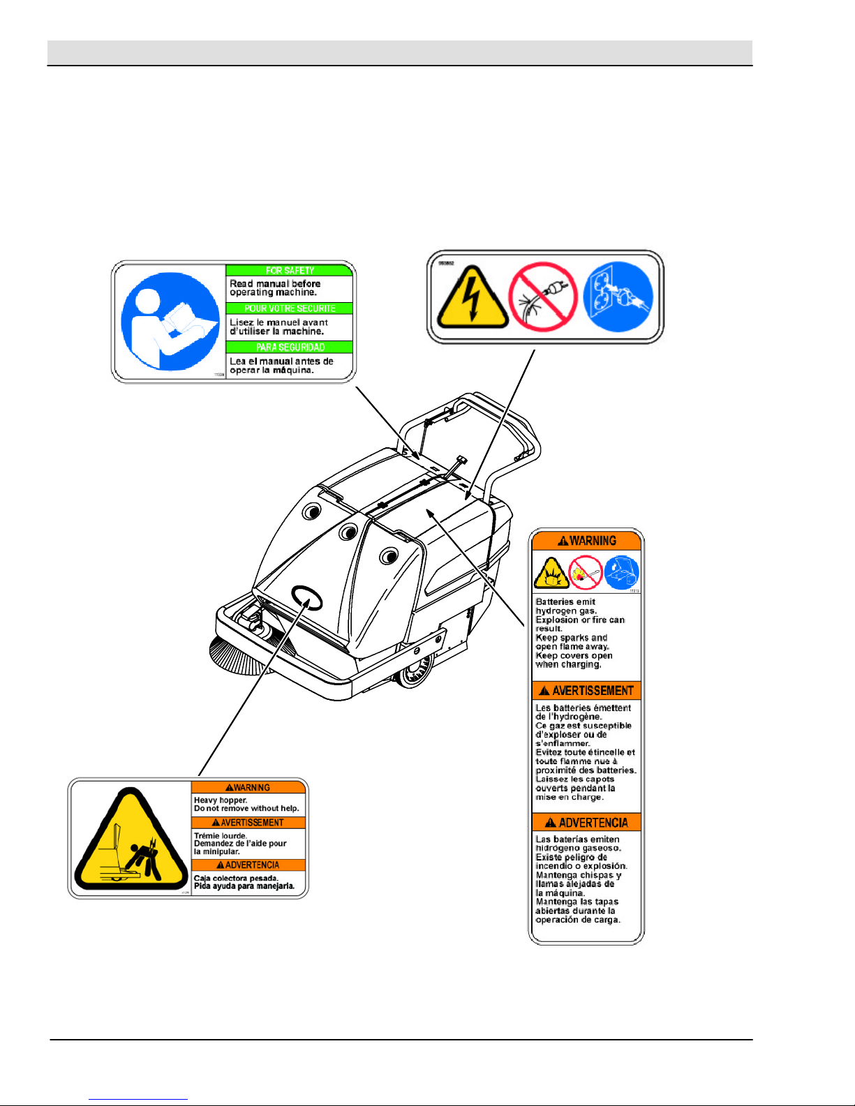
WARNING: Batteries emit hydrogen gas.
Explosion or fire can result. Keep sparks
and open flame away. Keep covers open
when charging.
WARNING: Disconnect battery cables and
charger plug before servicing machine. Do
not charge batteries with damaged power
supply cord. Do not modify plug.
If the charger supply cord is damaged or broken,
it must be replaced by the manufacturer or its
service agent or a similarly qualified person in
order to avoid a hazard.
WARNING: Heavy hopper. Do not remove
without help. Can cause back strain.
This machine is not equipped with explosion
proof motors. The electric motors will spark upon
start up and during operation which could cause
a flash fire or explosion if machine is used in an
area where flammable vapors/liquids or
combustible dusts are present.
FOR SAFETY:
1. Do Not Operate Machine:
-- Unless Trained And Authorized.
-- Unless Operation Manual Is Read And
Understood.
-- In Flammable Or Explosive Areas Unless
Designed For Use In Those Areas.
2. Before Starting Machine:
-- Make Sure All Safety Devices Are In Place
And Operate Properly.
3. When Using Machine:
-- Go Slow On Grades And Slippery
Surfaces.
-- Use Care When Backing Machine.
4. Before Leaving Or Servicing Machine:
-- Stop On Level Surface.
-- Set Parking Brake.
-- Turn Off Machine And Remove Key.
5. When Servicing Machine:
-- Avoid Moving Parts. Do Not Wear Loose
Jackets, Shirts, Or Sleeves When Working
On Machine.
-- Use Hoist Or Jack Of Adequate Capacity
To Lift Machine.
-- Wear Eye And Ear Protection When Using
Pressurized Air Or Water.
-- Disconnect Battery Connections Before
Working On Machine.
-- Avoid Contact With Battery Acid.
-- Use TENNANT Supplied Or Equivalent
Replacement Parts.
6. When loading/unloading machine onto/off
truck or trailer.
-- Turn off machine.
-- Use truck or trailer that will support the
weight of the machine.
-- Use winch. Do not push the machine
onto/off the truck or trailer unless the load
height is 380 mm (15 in) or less from the
ground.
-- Block machine tires.
-- Tie machine down to truck or trailer.

S10 SERVICE INFORMATIONSafety Information
S10 331585 (6--07)
vi
The following safety decals are mounted on the
machine in the locations indicated. If these, or any
decal becomes damaged or illegible, install a new
decal in its place.
FOR SAFETY LABEL -- LOCATED
ON THE CONTROL PANEL.
BATTERY CHARGING LABEL --
LOCATED ON THE LEFT SIDE
PANEL.
BACK STRAIN LABEL -- LOCATED
ON THE TOP OF THE HOPPER.
CHARGER CORD LABEL --
LOCATED NEAR CHARGER.

S10 SERVICE INFORMATION General Machine Information
1
S10 331585 (6--07)
GENERAL
MACHINE
INFORMATION
BEFORE CONDUCTING TESTS:
* Read and Follow ALL Safety Warnings and Precautions as mentioned
at the beginning of this manual
* Always unhook Battery when removing or replacing components
DURING TESTS:
* Call Technical Services if Diagnostic Time Exceeds One Hour With
Unknown Cause or Course of Action
NOTE: Troubleshooting charts may be shown with optional equipment. The optional equipment
may not be specified in these charts. Some machines may not be equipped with all components
shown.

S10 SERVICE INFORMATION
General Machine Information
S10 331585 (6--07)
2
SPECIFICATIONS
GENERAL MACHINE DIMENSIONS/CAPACITIES
Item Dimension/capacity
Length 1570 mm (62 in)
Height (maximum) 990 mm--1120 mm (39 in--44 in)
Width (with out side brush) 920 mm (36.25 in)
Track--front 790 mm (31 in)
Wheel base 595 mm (23.5 in)
Main brush width 660 mm (26 in)
Main brush diameter 255 mm (10 in)
Side brush diameter 430 mm (17 in)
Sweeping path width (with side brush) 860 mm (34 in)
Hopper volume capacity 0.08 m#(2.8 cu ft)
Hopper weight capacity 68 kg (150 lb)
GVWR 345 kg (760 lb)
Dust filter (pleated panel filter element) 4.55 m@(49 sq. ft)
GENERAL MACHINE PERFORMANCE
Item Measure
Turning radius 1730 mm (68 in)
Travel speed forward (maximum) 4.7 Km/h (2.9 mph)
Travel speed reverse (maximum) 4.5 Km/h (2.8 mph)
POWER TYPE
System Drive Type
Propelling Belt to chain
Differential Belt
Wheel Drive Chain
Main Brush Belt
Side Brush Belt
Vacuum Fan Belt
Type VDC amp Hz Phase VAC
Charger: Auto / Selectable AC Voltage Input 24 11 50/60 1100--240
Type Use VDC kW (hp)
Electric Motor Propelling 24 0.75 (1)
Type Quantity Volts Ah Rating Weight
Batteries 212 155 @ 20 hr rate 38 kg (83 lb)

S10 SERVICE INFORMATION General Machine Information
3
S10 331585 (6--07)
TIRES
Location Type Size
Front (2) Solid 250 mm x 51 mm (10 in x 2 in)
Rear (1) Solid 130mmx38mm(5inx1.5in)
MACHINE DIMENSIONS
920 mm
(36.25 in)
1570 mm
(62 in)
990 mm--1120 mm
(39in--44in)
03131

S10 SERVICE INFORMATION
General Machine Information
S10 331585 (6--07)
4

S10 SERVICE INFORMATION Maintenance & Repair
S10 331585 (6--07) 5
MAINTENANCE
&REPAIR
BEFORE CONDUCTING TESTS:
* Read and Follow ALL Safety Warnings and Precautions as mentioned
at the beginning of this manual
* Always unhook Battery when removing or replacing components
DURING TESTS:
* Call Technical Services if Diagnostic Time Exceeds One Hour With
Unknown Cause or Course of Action
NOTE: Troubleshooting charts may be shown with optional equipment. The optional equipment
may not be specified in these charts. Some machines may not be equipped with all components
shown.

S10 SERVICE INFORMATIONMaintenance & Repair
S10 331585 (6--07)
6
MAINTENANCE
1
2
3
4
7
8
9
13
16
2
5, 10, 11, 15, 17
5
4
617
MAINTENANCE CHART
Interval Key Description Procedure
Lubricant/
Fluid
No. of
Service
Points
Daily 2Brush skirts Check for damage, wear, and
floor clearance
-- 5
3Main brush Check for damage, wear, debris -- 1
8Side brush Check for damage, wear, debris -- 1
7Hopper Check seals for damage and
wear
-- 3
25 Hours 1Battery cells Check electrolyte level DW 2
3Main brush Check floor pattern
(after initial 25 hours only)
-- 1
5Drive chains Check and adjust tension
(after initial 25 hours only)
-- 2

S10 SERVICE INFORMATION Maintenance & Repair
S10 331585 (6--07) 7
50 Hours 14 Vacuum fan belt Check tension and wear -- 1
10 Propelling belts Check tension and wear -- 2
10 Main brush belts Check tension and wear -- 2
9Side brush belts Check tension and wear -- 2
8Side brush Check pressure -- 1
3Main brush Check floor pattern
Rotate end--for--end
-- 1
4Brush arm pivots Lubricate SPL 2
13 Rear caster Lubricate SPL 1
7Hopper Check floor clearance -- 1
17 Battery charger cable Check for wear and damage -- 1
100 Hours 5Drive chains Check and adjust tension -- 2
Lubricate SO 2
6Dust filter Clean or replace -- 1
11 Self adjusting sheave Lubricate SPL 1
1Batteries Clean top surface and terminals -- 2
17 Differential Lubricate SPL 1
400 Hours 15 Propelling motor Blow out dust and inspect -- 1
16 Side brush gear box Check lubricant level GL 1
LUBRICANT/FLUID
DW -- Distilled water
SPL -- Special lubricant, Lubriplate EMB grease, TENNANT Part No. 01433--1
SO -- Spray lubricant
GL -- SAE 90 Weight gear lubricant
NOTE: More frequent intervals may be required in extremely dusty conditions.

S10 SERVICE INFORMATIONMaintenance & Repair
S10 331585 (6--07)
8
LUBRICATION
DRIVE CHAINS
Check the tension and lubricate the drive chains (A)
with a penetrating-type spray lubricant after every 100
hours of operation.
A
B
03139
A. Drive Chain
B. Differential
DIFFERENTIAL
Lubricate the differential (B) every 100 hours of
operation. The differential grease fitting is located on
the drive shaft inside the drive sheave.
BRUSH ARM PIVOTS
Lubricate the brush arm pivots after every 50 hours of
operation.
REAR CASTER
Lubricate the rear caster after every 50 hours of
operation.

S10 SERVICE INFORMATION Maintenance & Repair
S10 331585 (6--07) 9
SIDE BRUSH GEAR BOX
Check the side brush gear box fluid level after every
400 hours of operation. Remove the breather and fill
the gear box to within 6 mm (0.25 in) of the top.
03144
SELF ADJUSTING SHEAVE
Lubricate the sheave shaft after every 100 hours of
operation. Avoid getting oil on the belt or sheave belt
surfaces.
03141

S10 SERVICE INFORMATIONMaintenance & Repair
S10 331585 (6--07)
10
BATTERIES
The batteries are designed to hold their power for
long periods of time. The lifetime of the batteries is
limited to number of charges the batteries receive. To
get the most life from the batteries, recharge them
immediately when the battery discharge indicator
begins to blink.
FOR SAFETY: When servicing machine, wear
protective gloves when handling batteries or
battery cables. Avoid contact with battery acid.
After every 100 hours of use check for loose battery
connections and clean the surface of the batteries,
including terminals and cable clamps, using a strong
solution of baking soda and water. Brush the solution
sparingly over the battery tops. Do not allow any
baking soda solution to enter the batteries. Use a wire
brush to clean the terminal posts and the cable
connectors. Wipe off all cleaning solution residue.
After cleaning, apply a coating of clear battery post
protectant to the terminals and the cable connectors.
Keep the tops of the batteries clean and dry.
Objects made of metal can potentially short circuit the
batteries. Keep all metallic objects off the batteries.
Replace any worn or damaged wires. Replace any
defective batteries. To dispose of batteries, contact a
battery dealer or your Tennant Service representative.
LEAD ACID BATTERIES
Check the electrolyte level in each battery cell before
and after charging, and after every 25 hours of
operation. Never add acid to the batteries. Add
distilled water only. Always keep the battery caps on,
except when adding water or taking hydrometer
readings.
Using a hydrometer, measure the specific gravity to
determine the charge level and condition of the
batteries. If one or more of the battery cells test lower
than the other battery cells (0.050 or more), the cell is
damaged, shorted, or is near failure. Completely
recharge the batteries and then retest.
04380

S10 SERVICE INFORMATION Maintenance & Repair
S10 331585 (6--07) 11
NOTE: Do not take readings immediately after adding
distilled water. If the water and acid are not thoroughly
mixed, the readings may not be accurate. Check the
hydrometer readings against the following chart to
determine the remaining battery charge level:
SPECIFIC GRAVITY BATTERY
at 27_C(80_F) CHARGE
1.265 100% Charged
1.225 75% Charged
1.190 50% Charged
1.155 25% Charged
1.120 Discharged
NOTE: If the readings are taken when the battery
electrolyte is any temperature other than 27_C(80_
F), the reading must be temperature corrected. Add
or subtract to the specific gravity reading 0.004, 4
points, for each 6_C(10_F) above or below 27_C
(80_F).
CHARGING BATTERIES
The following charging instructions are intended for
battery chargers supplied with the machine.
After every 50 hours check the battery charger cord
for damage.
To prolong the life of the batteries only recharge the
batteries if the machine was used for a total of 30
minutes or more. Do not leave batteries discharged
for lengthy periods.
WARNING: Fire Or Explosion Hazard.
Batteries emit hydrogen gas. Keep sparks and
open flame away. Keep battery compartment open
when charging.
FOR SAFETY: When servicing batteries, wear
protective gloves and eye protection when
handling batteries and battery cables. Avoid
contact with battery acid.
Make sure the charger profile is properly set for the
battery type before charging. Failure to properly set
profile will result in battery damage. To determine the
battery type, see battery label. Contact the battery
supplier if not specified.
To verify the charger profile setting, connect the
charger cord into an electrical receptacle. If the LED
labeled “GEL” is on, the charger is set for Gel
(sealed) batteries. If the LED is off, the charger is set
for Wet/lead acid (flooded) batteries.
To change the charger profile, unplug the charger,
remove the “Charger Profile Selection” panel, and
position the switch towards the proper setting, “GEL”
or “Flooded” .
1. Transport the machine to a well--ventilated area
for charging.
FOR SAFETY: Before leaving or servicing
machine; stop on level surface, set parking brake
(if equipped), and turn off machine.
2. If charging wet (lead acid) batteries check the
fluid level before charging (See BATTERY
MAINTENANCE).
3. Remove the battery compartment covers for
ventilation when charging.

S10 SERVICE INFORMATIONMaintenance & Repair
S10 331585 (6--07)
12
4. Connect the charger cord into a properly
grounded electrical receptacle. The charger will
start automatically within a few seconds. The
LEDs will display the charging state as
described in the following table.
CHARGING STATE LED DISPLAY
Charging State 50% LED 75% LED 100% LED
0--50% charged Blinking Off Off
50--75% charged On Blinking Off
75--100%
charged
On On Blinking
100% charged On On On
Abnormal Cycle* Off Off Blinking
Fault detected * Blinking Blinking Blinking
* See the On--board Battery Charger Fault Codes table.
When a fault occurs, the charger will also sound an alarm.
NOTE: The machine will not operate once the battery
charger is connected.
5. Once the batteries are fully charged, the charger
will stop suppling power, but will continue to
monitor the battery voltage. The charger will
restart if the batteries self--discharge.
NOTE: The charger may take up to 30 seconds to
turn off once the charger cord is disconnected. During
this time, the machine will not power up. The charger
cord must also be disconnected for 30 seconds
before the charger can be restarted.
6. Unplug the charger cord from the electrical
receptacle and stow the cord beneath the left
battery.
NOTE: To avoid damaging the charger cord, do not
pul on the cord to unplug the charger from the
electrical receptacle. Use the plug to unplug the cord
from the electrical receptacle.
7. Reinstall the battery compartment covers.
LED FAULT CODE FAULT SOLUTION
3 LEDs blink once
t
d
l
Loose charger cable connection. Check charger cable connection.
repeatedly Loose or damaged battery cable. Check battery cable connections.
Defective Battery. Replace battery.
3 LEDs blink twice
repeatedly
Input voltage is out of range. Try using a different wall outlet.
3LEDsblinkthree
times repeatedly
Safety thermostat exceeded maximum
internal temperature.
Open battery compartment to promote air
circulation or move machine to a cooler
climate.
3LEDsblinkfour
times repeatedly
Output current exceeds a limit. Disconnect charger cord, wait 30 seconds,
then plug back in. If fault continues replace
charger or contact TENNANT Service.
100% LED blinks
while the 50% and
75% LEDs are off.
Abnormal cycle. Safety timer exceeded
the 18 hour charging time.
Battery maintenance required or replace
battery.

S10 SERVICE INFORMATION Maintenance & Repair
S10 331585 (6--07) 13
ELECTRIC MOTORS
The electric propelling motor is serviceable. The
propelling motor is located underneath the battery
compartment.
Blow out the dust and inspect the motor brushes in
the motor after every 400 hours of operation.
If the brushes have been worn to less than 10 mm
(0.38 in) in length, replace them.
If the commutator is worn or rough, the motor
armature should be removed and serviced, or
replaced.
BELTS AND CHAINS
PROPELLING BELTS
Check the propelling belts for wear and tension after
every 50 hours of operation.
CHECKING AND ADJUSTING THE PROPELLING
BELT TENSION
FOR SAFETY: Before leaving or servicing
machine; stop on level surface, set parking brake
(if equipped), and turn off machine.
1. Remove the access cover, bumper, and cover.
2. Observe the position of the clutch plate bolt (C)
with no pressure on the clutch handle. It should
be approximately in the center of the slot (D).
3. Press the clutch handle to tighten the forward
propelling belt (G). The clutch handle should be
7to13mm(0.25to
0.50 in) from the stationary handle. Observe the
position of the clutch plate bolt (C). It should not
touch the end of the slot (D). If the handle and
bolt are in the proper position, proceed to step
7; if not, continue with step 4 to readjust forward
belt tension.
A
B
C
D
H
GF
E
I
03151
A. Motor
B. Clutch Plate
C. Clutch Plate Bolt
D. Bolt Slot
E. Forward Belt Idler Sheave
F. Reverse Propelling Belt
G. Forward Propelling Belt
H. Reverse Belt Idler Sheave
I. Belt Guide

S10 SERVICE INFORMATIONMaintenance & Repair
S10 331585 (6--07)
14
4. Loosen the forward idler sheave bolt (E) and
slide the idler sheave down to tighten the belt
(G) (this also increases distance between clutch
handle and stationary handle); slide the sheave
up to loosen the belt (this also reduces distance
between clutch handle and stationary handle).
5. Tighten the idler sheave bolt.
6. Recheck handle and bolt positions. Repeat as
necessary to adjust belt tension.
NOTE: After adjusting the forward belt, it may contact
the belt guide when engaged causing a whining noise.
To stop the noise, bend the guide up out of the belt’s
way.
7. Pull the clutch handle to tighten the reverse
propelling belt. Observe the position of the
clutch plate bolt (C). It should not touch the end
of the slot (D). If the bolt is in the proper
position, proceed to step 11; if not, continue with
step 8 to readjust reverse belt tension.
NOTE: If the reverse belt is too tight, it will require
excessive clutch handle pressure to propel machine
in the forward direction. It may also cause the
machine to creep backward when the handle is
released. If the reverse belt is too loose, the machine
will not propel backward.
8. Loosen the reverse idler sheave bolt (H) and
slide the idler sheave to the rear to tighten the
belt (F); slide the sheave forward to loosen the
belt.
9. Tighten the reverse idler sheave bolt (H).
10. Pull the clutch handle to recheck the position of
the clutch plate bolt (C). Repeat as necessary to
adjust belt tension.
11. Check steering effort. After repairing or
replacing drive system parts, effort may
increase due to poor alignment. To correct, do
the following:
A. Loosen the bearing flanges as well as the
split coupling bolts.
B. Snug one split coupling bolt.
C. Align the propelling belts. Check for
clearance between the differential and the
locking collar.
NOTE: Minimum clearance between differential and
sheave is 0.3 mm (0.010 in).
D. While holding belt alignment, pull the shaft
away from the differential.
E. Tighten the center and left bearing flanges.
Check for hard rotation of shaft.
F. Tighten the center and left bearing collars.
G. Pull the short differential shaft away from
differential to spread the differential gears.
H. Tighten the right side bearing flange. Tap
bearing before tightening.
I. Tighten the right bearing collar.
J. Check for free spinning of differential.
Loosen the center and right bearing flanges
if it is not spinning freely. Tap and retighten.
K. Align and tighten sprockets. Chains must
be slack to minimize steering effort.
12. Reinstall the access cover, and right side cover,
and bumper.
Other manuals for S10
1
Table of contents
Other Tennant Blower manuals

Tennant
Tennant A80 User manual

Tennant
Tennant A60 User manual

Tennant
Tennant SweepSmart S20 ELECTRIC Operating and installation instructions

Tennant
Tennant 800 User manual

Tennant
Tennant 6500 Training manual

Tennant
Tennant 280 User manual

Tennant
Tennant sentinel User manual

Tennant
Tennant S12 User manual

Tennant
Tennant S680 User manual

Tennant
Tennant 810 LPG User manual

Tennant
Tennant 6600 User manual

Tennant
Tennant 6100 Training manual

Tennant
Tennant 800 User manual

Tennant
Tennant sentinel User manual

Tennant
Tennant S5 User manual

Tennant
Tennant 830 User manual

Tennant
Tennant 6100E Training manual

Tennant
Tennant S8 User manual

Tennant
Tennant S7 User manual

Tennant
Tennant S3 Product manual